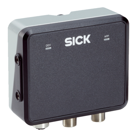
SICK RFH6 Series Manual

Technical Information
SICK
RFH6xx Function Block
Version V2.X
SICK RFH6XX PNDP Function Block for
Siemens S7-Controls (Step7 V5.5)

Date: 12.06.2014 2
Table of Content
1 About this document........................................................................................................ 3
1.1 Function of this document............................................................................................ 3
1.2 Target group................................................................................................................ 3
2 General Information ......................................................................................................... 4
3 Hardware configuration ................................................................................................... 5
3.1 Supported PLC............................................................................................................ 5
3.2 Supported fieldbus gateways / sensors........................................................................ 5
3.3 Configuration in Step7 ................................................................................................. 5
4 Description of Function Block......................................................................................... 7
4.1 Function block specification ......................................................................................... 7
4.2 Operation Mode........................................................................................................... 8
4.3 Behavior in the case of an error..................................................................................10
4.4 Timing.........................................................................................................................10
4.5 Value transfer .............................................................................................................11
4.5.1 Mode....................................................................................................................12
4.5.2 Lock block ............................................................................................................13
4.5.3 Inventory ..............................................................................................................13
4.5.4 Read Tag .............................................................................................................14
4.5.5 Write Tag..............................................................................................................14
4.5.6 Free Command ....................................................................................................15
4.5.7 Reading Result.....................................................................................................15
4.6 Receipt of read results > 200 Byte..............................................................................16
5 Parameter.........................................................................................................................18
6 Error Codes .....................................................................................................................21
7 Examples .........................................................................................................................24
7.1 Reading out tag contents............................................................................................25
7.2 Writing of tag contents ................................................................................................26

Technical Information
RFH6xx PNDP
Function Block
Date: 12.06.2014 3
1 About this document
Please read this chapter carefully before you start working with this operation manual and
SICK RFH6XX function block.
1.1 Function of this document
This operation manual describes how to use SICK RFH6XX PNDP Function Block. It is used
for guiding technical personnel working for the machine manufacturer / operator in project
planning and commissioning.
1.2 Target group
This Operation Manual is aimed for specialists, such as technicians and engineers.

Technical Information
RFH6xx PNDP
Function Block
Date: 12.06.2014 4
2 General Information
The function block “SICK RFH6XX PNDP” is used for the communication between a
SIMATIC control and a SICK RFH6XX RFID interrogator.
The following image shows the function block in the view of the function block diagram
(FBD).
Image 1: SICK RFH6XX PNDP function block
Features of the function block:
- Sending of a trigger (CoLa
i
command) via the PLC
- Receiving of read results (defined in SOPAS-ET
ii
output format)
- Read and write transponder contents
- Carrying out an Inventory-command (display all transponders in the reading field)
- Permanent locking of transponder blocks
- Carrying out a communication test
- Communication via free selectable CoLa commands (CoLa-A protocol)
- Addressing of devices which communicate via CAN-Bus
i
The Command Language (CoLa) is an internal SICK protocol for the communication with SOPAS devices
ii
SOPAS-ET is an engineering tool for the configuration of SICK sensors

Technical Information
RFH6xx PNDP
Function Block
Date: 12.06.2014 5
3 Hardware configuration
3.1 Supported PLC
The function block must only be used with a S7-300 / S7-400 controller family. Only PLC’s
with integrated fieldbus interfaces are supported. The communication via a communication
processor is not supported from this function block.
3.2 Supported fieldbus gateways / sensors
The SICK sensor communicates via fieldbus (Profibus/Profinet) with the PLC. If the sensor
cannot support the fieldbuses mentioned above, Gateway modules can be used.
The following Gateways are supported from the function block:
- CDM 425 (Profinet), starting with firmware version V3.31
- CDF 600 (Profibus), starting with firmware version V1.15
- CDM 420 incl. CMF400 Profibus Module, starting with firmware version V1.100
Necessary RFH firmware version:
- RFH6xx, starting with firmware version V1.31
3.3 Configuration in Step7
Before the function block can be used, the RFH has to be projected in the hardware configu-
ration in Step7. Therefore, the corresponding device file (GSD-file) has to be imported in the
hardware library in Step7.
The function block is laid out especially for the handshake mode (Confirmed Messaging Pro-
tocol). Please do only use HS-modules with a length between 8…128 Bytes. The used ad-
dresses can be projected in the periphery or outside. An address assignment on the periph-
ery to which a partly process image with OB6x-connection (alarm of asynchronous trigger) is
assigned, must not be used.
Image 2 shows an example configuration of a RFH in combination with a CDF600 Profibus
Gateway.

Technical Information
RFH6xx PNDP
Function Block
Date: 12.06.2014 6
Image 2: Step7 Example of hardware configuration

Technical Information
RFH6xx PNDP
Function Block
Date: 12.06.2014 7
4 Description of Function Block
The function block is working asynchronously, which means the processing is done via vari-
ous function block call ups. Therefore it is necessary that the function block is called up cycli-
cally in the user program.
The RFH function block encapsulates “SICK CCOM PNDP”(FB10), which allows the com-
munication between PLC and sensor. FC10 (SICK COLA ACCESS) is used internally for the
interpretation of CoLa-telegrams.
4.1 Function block specification
Number of function block: FB73
Name of function block: SICK RFH6XX PNDP
Version: 2.1
Called up function blocks: SFC 14 (DPRD_DAT)
SFC 15 (DPWR_DAT)
SFC20 (BLKMOV)
SFB4 (TON)
FB10 (SICK CCOM PNDP)
FC10 (SICK COLA ACCESS)
Used data blocks: DB73 (SICK RFH DATA)
Function block call up: Cyclically
Used flag: none
Used counter: none
Used register: AR1, AR2 (for multi instance call up)
Multi instance capable: yes
Language: Step7-AWL
Step7 Version: Simatic Step7 V5.5
The system functions (SFCs) used in the function block have to be available on the respec-
tive PLC.
When changing the function block numbers, the respective calls in the function block SICK
RFH6XX PNDP have to be updated.

Technical Information
RFH6xx PNDP
Function Block
Date: 12.06.2014 8
4.2 Operation Mode
In order to use the RFH function block, the following communication parameters have to be
set:
IN_ADDR: Projected entry point address of the used input modules of the input area. The
entry point address is fixed by the projecting of the hardware (see chapter 3.3). The value
has to be in hexadecimal format (e.g. address 256 = W#16#100).
IN_LEN: Length of the used input modules in the hardware configuration. The length of the
input module is fixed by the projecting of the hardware (see chapter 3.3).
OUT_ADDR: Projected entry point address of the used output module of the output area.
The output address is fixed by the projecting of the hardware (see chapter 3.3). The value
has to be in hexadecimal format (e.g. address 256 = W#16#100).
OUT_LEN: Length of the used output module in the hardware configuration. The length of
the output module is fixed by the projecting of the hardware (see chapter 3.3).
DATA: The data block (DB73) belonging to the function block contains in- and output param-
eter of the supported function block actions. The data block has to be transferred to the input
parameter “DATA” of the function block.
Realizable function block functions:
- Trigger on Opens the reading gate of the device per CoLa command
- Trigger off Closes the reading gate of the device per CoLa command
- Read Tag Read transponder data
- Write Tag Write transponder data
- Inventory The inventory action searches in the reading area of the RFH
for active transponders and returns their UID.
- Lock Block Permanent locking of a selected transponder block
- Stay Quiet Muting of a RFID tag which is in the field.
- Communication test Checks if the device can be reached via „sRI0“ command
- Free Command Executes a free selectable CoLa command
- Reset Reset of the communication
In order to execute a function block action (TRIG_ON, RD_TAG, etc.), the desired action has
to be selected first. Only one action can be executed at the same time. In order to do the
action, the parameter START_REQ has to be triggered with a positive edge (signal change
from a logical cero to one). As long as no valid device answer has to be received, this is sig-
nalized via the parameter REQ_BUSY.
If the function block signalizes REQ_DONE = TRUE at the output parameter, the action has
been done successfully. If, for this action (e.g. RD_TAG) data has been requested from the
device, it will be copied into the respective data area of the UDTs.
Data that is sent per trigger (TRIG_ON, TRIG_OFF) or directly from the device (e.g. direct
trigger via a light switch), is stored in the data function block (ReadingResult.arrResult). The
output parameter RD_DONE indicates for one PLC cycle, that new data has been received.
The from the device sent data can be changed in the SOPAS output format.

Technical Information
RFH6xx PNDP
Function Block
Date: 12.06.2014 9
Image 3: SOPAS output format

Technical Information
RFH6xx PNDP
Function Block
Date: 12.06.2014 10
4.3 Behavior in the case of an error
If there is a wrong input value or a wrong input circuit of the function block, an error bit
(ERROR) is set and an error code (ERRORCODE) will be given out. In this case there is no
further processing. The diagnosis parameter (ERROR and ERRORCODE) of the routine
maintain their value until a new request has been started.
Via the RESET Bit you can reset the communication between the sensor and the PLC. The
reset is being carried out as soon as the RESET Bit has been preselected and the
START_REQ Bit has been triggered with a positive edge (signal change from cero to one).
The REQ_BUSY Bit signalizes that the order is in process. As soon as the reset routine is
terminated, REQ_DONE Bit is being set.
Because of the reset the following actions are done:
- Reset of the counter of confirmed messaging protocol (device communication)
- Reset of all error messages
4.4 Timing
1: Request through pos edge to START_REQ
The desired action (here RD_Tag) has to be selected in advance / at the same time. Only
one action must be selected at the same time, otherwise there is a break-down with
„ERROR“.
2: If all commands are sent and all replies are received, the action is ended with
„REQ_Done“. If the action is faulty, it will be terminated with „ERROR“. If terminated with
„ERROR“, you can find the error in „ERRORCODE“.
Image 4: Timing Diagram

Technical Information
RFH6xx PNDP
Function Block
Date: 12.06.2014 11
4.5 Value transfer
The data function block “SICK RFH DATA” (DB73) contains input and output parameters of
all supported function block actions. The data function block can be re-named according to
the user program. The data structure is pre-defined and must not be changed (except for the
last entry (ReadingResult.arrResult) (see chapter 4.6: Receipt of read results > 200 Byte).
Image 5: Structure of SICK RFH DATA DBs

Technical Information
RFH6xx PNDP
Function Block
Date: 12.06.2014 12
4.5.1 Mode
The RFH can communicate only with one transponder at the same time. Therefore, reading
and writing orders are always executed in an address. In order to identify the transponders,
the UID (Unique Identifier) is being used.
In order to determine with which transponder the UID should communicate, the function
block supports two modes:
Mode 1: It is always communicated with the transponder that is actually in the reading field.
This mode can only be used if there is exactly one tag in the field.
Mode 2: A from the user defined transponder-UID is used for the communication.
Parameter
Declaration
Data type
Description
Mode.bMode
Input
BOOL
Address mode
FALSE: Mode 1 active
TRUE: Mode 2 active
Mode.arrUID
Input/Output
INT
Transponder Identification (UID)
In mode 1 the UID is read automatically
Table 1: Mode Parameter

Technical Information
RFH6xx PNDP
Function Block
Date: 12.06.2014 13
4.5.2 Lock block
With the help of the Lock Block Action you have the possibility to save any block on the RFID
tag from re-writing. The block number has to be inserted via the parameter iLockBlock before
carrying out the function block action. The action locks the selected block permanently. A de-
blocking is not possible.
Parameter
Declaration
Data type
Description
iLockBlock
INPUT
INT
Number of the block that should be
prevented from re-writing.
4.5.3 Inventory
The Inventory Action searches in the entry area of the sensor for active transponders. For
each identified transponder (max. 5 transponders) the function block displays the following
information:
Parameter
Declaration
Data type
Description
Inventory.
iNumRetTags
Output
INT
Number of identified transponders
Inventory.
arrTagInfo[ ].nError
Output
BYTE
Transponder Errorcode (see RFH
operation manual)
Inventory.
arrTagInfo[ ].nRSSI
Output
BYTE
RSSI (signal strength of the identified
transponder)
Inventory.
arrTagInfo[ ].nDSFID
Output
BYTE
DSFID of the identified transponder
Inventory.
arrTagInfo[ ].arrUID
Output
ARRAY
[1..8]
OF BYTE
UID of the identified transponders in
HEX-format

Technical Information
RFH6xx PNDP
Function Block
Date: 12.06.2014 14
4.5.4 Read Tag
The Read Tag action reads a defined data area of the tag. This action can only be done for
one tag. With which transponder should be communicated, depends on the selected mode
(see chapter 4.5.1).
Before the reading you have to decide which blocks on the transponder should be read. After
a successful reading, the byte length of the read data as well as user data are stored.
Parameter
Declaration
Data type
Description
ReadTag.
iStartBlock
Input
INT
Block number at which the reading
should be started
ReadTag.
iNumBlocks
Input
INT
Number of blocks that should be read
ReadTag.
iDataLength
Output
INT
Length of the read content in bytes
ReadTag.arrData
Output
ARRAY
[1..128]
OF BYTE
Content of the read blocks
Table 2: Read Tag Parameter
4.5.5 Write Tag
The Write Tag function writes onto a defined data area of a tag. The action can only be done
for one tag. With which transponder should be communicated, depends on the selected
mode (see chapter 4.5.1).
Before the writing you have to decide, at which block the writing starts and how many blocks
should be read. Since the length of a block can differ, depending on the type of tag, it also
has to be inserted (see information of the tag fabricant).
Parameter
Declaration
Data type
Description
WriteTag.
iStartBlock
Input
INT
Block number at which the writing
should be started
WriteTag.
iNumBlocks
Input
INT
Number of blocks that should be written
WriteTag.
iBlockSize
Input
INT
Byte size of a block
Valid value area:
[4,8,12,16,…]
WriteTag.arrData
Input
ARRAY
[1..128]
OF BYTE
Data that should be written into the
transponder blocks.
Table 3: Write Tag Parameter

Technical Information
RFH6xx PNDP
Function Block
Date: 12.06.2014 15
4.5.6 Free Command
With the help of a free command you have the possibility to communicate via a valid CoLa
command with the RFH. Hence it is necessary to store the command in the parameter
“arrCommand” of the structure “FreeCommand”. The character length of the transferring
command is written in the parameter “iCommandLength”. The commands can be looked up
in the device description or SOPAS-ET.
Parameter
Declaration
Data type
Description
FreeCommand.
iCommandLength
Input
INT
Character length of the transferring
CoLa command.
Valid value area
[1..100]
FreeCommand.
arrCommand
Input
ARRAY
[1..100]
OF CHAR
Free selectable CoLa command
(commands see device documenta-
tion).
FreeCommand.
iResultLength
Output
INT
Byte length of the receiving CoLa tel-
egram.
FreeCommand.
arrResult
Output
ARRAY
[1..100]
OF CHAR
Received answer of the sent CoLa
telegram.
Table 4: Free Command Parameter
4.5.7 Reading Result
In the array “ReadingResult.arrResult” data is stored, which is sent via trigger order
(TRIG_ON, TRIG_OFF) or directly from the device (e.g. direct trigger via a light switch). The
output parameter RD_DONE signalizes whether data has been received.
Parameter
Declaration
Data type
Description
ReadingResult.
nCounter
Output
BYTE
The receipt counter is incremented by
one as soon as a new read result has
been received.
Value area:
[0x00..0xFF]
ReadingResult.
iLength
Output
INT
Byte length of the receiving read re-
sult.
ReadingResult.
arrResult
Output
ARRAY
[1..200]
of BYTE
Receiving answer of a trigger signal
(can be defined via the SOPAS output
format).
The maximal length of the receiving
data is 200 Bytes. Chapter 4.6 de-
scribes the procedure when receiving
longer data telegrams.
Table 5: Reading Result Parameter

Technical Information
RFH6xx PNDP
Function Block
Date: 12.06.2014 16
4.6 Receipt of read results > 200 Byte
The function block is laid out to receive read results up to a length of 200 Bytes. If longer
data has to be received, the routine has to be changed at the following positions:
Change in SICK RFH DATA UDT:
In the delivered UDT (DB73) the length of the array “ReadingResult.arrResult”has to be
adapted in such a way, that the read result which has to be received fits into the data area of
the variable.
Image 6: Receipt of read results > 200 Bytes (change in the UDT)
Change in the SICK RFH6XX PNDP function block:
In the static area of the variable survey, the length of the variable “arrRecord” has to be
adapted in such a way, that the read result fits into the data area of the variable. The array
must not be below a length of 500 bytes, but it has to be larger or equal to the length of the
“ReadingResult.arrResult”.
Image 7: Receipt of read results > 200 Bytes (change in the FB declaration)
The new defined array lengths have to be inserted into the network 3 of SICK RFH6XX
PNDP function block.

Technical Information
RFH6xx PNDP
Function Block
Date: 12.06.2014 17
Image 8: Receipt of read results > 200 bytes (change in the UDT code)
After the change the instance of the function block has to be updated. Afterwards the
changed UDT as well as the function block have to be transferred to the PLC together with
the updated instance.

Technical Information
RFH6xx PNDP
Function Block
Date: 12.06.2014 18
5 Parameter
Parameter
Declara-
tion
Data
type
Storing
area
Description
EN
INPUT
BOOL
I,M,D,L,
Const.
Enable entry (KOP and FUP)
IN_ADDR
INPUT
WORD
I,M,D,L,
Const.
Projected starting address of the E-area
of the chosen module.
IN_LEN
INPUT
INT
I,M,D,L,
Const.
Length of the used input module in the
hardware configuration.
Valid value area: [8..128]
OUT_ADDR
INPUT
WORD
I,M,D,L,
Const.
Projected starting address of the A-area
of the chosen module.
OUT_LEN
INPUT
INT
I,M,D,L,
Const.
Length of the used output module in the
hardware configuration.
Valid value area: [8..128]
CAN_ID
INPUT
INT
I,M,D,L,
Const.
CAN-ID of the sensor to be contacted.
If no CAN network is used, the CAN-ID
= 0
The master resp. multiplexer is always
contacted with CAN-ID = 0, even if an-
other CAN-ID is assigned.
TOUT
INPUT
TIME
I,M,D,L,
Const.
Time after which a timeout error is pro-
voked.
START_REQ
INPUT
BOOL
I,M,D,L
Positive edge:
Carrying out the selected function block
action.
TRIG_ON
INPUT
BOOL
I,M,D,L,
Const.
Function block action: Carrying out a
device trigger (open trigger window)
TRIG_OFF
INPUT
BOOL
I,M,D,L,
Const.
Function block action: Carrying out a
device trigger (close trigger window)
The from the device sent result
(SOPAS output format) is stored in the
variable „ReadingResult.arrResult“of
the data structure (DB73).
RD_TAG
INPUT
BOOL
I,M,D,L,
Const.
Reading out tag contents:
Therefore it is necessary that the pa-
rameters in the structure „ReadTag“ are
assigned with valid values (see chapter
4.5.4).
Which transponder should be read de-
pends on the selected address mode
(see chapter 4.5.1).

Technical Information
RFH6xx PNDP
Function Block
Date: 12.06.2014 19
Parameter
Declara-
tion
Data
type
Storing
area
Description
WR_TAG
INPUT
BOOL
I,M,D,L,
Const.
Writing tag contents.
Therefore it is necessary that the pa-
rameters of the structure „WriteTag“ are
assigned with valid values (see chapter
4.5.5).
Which transponder should be written
depends on the selected address mode
(see chapter 4.5.1).
INVENTORY
INPUT
BOOL
I,M,D,L,
Const.
Searches for active transponders in the
entry area and transmits their UID,
DSFID and RSSI (signal strength).
LOCK_
BLOCK
INPUT
BOOL
I,M,D,L,
Const.
Prevents a defined block from re-
writing.
This requires that the parameter
iLockBlock in the transferring data func-
tion block has a valid block number
(see chapter 4.5.5).
This action blocks the selected block
permanently. A de-blocking is not pos-
sible.
STAY_QUIT
INPUT
BOOL
I,M,D,L,
Const.
Mutes the RFID tag which is in the field.
This action can only be done if the HF-
field of the RFID device is switched on
permanently (see SOPAS Tran-
sponder communication HF-Feld).
COM_TEST
INPUT
BOOL
I,M,D,L,
Const.
Carrying out of a communication test.
REQ_DONE= TRUE:
Communication OK
REQ_DONE= FALSE:
Communication not OK
FREE_
COMMAND
INPUT
BOOL
I,M,D,L,
Const.
Function block action: Carrying out a
free command.
This requires that the UDTs (DB73) in
the structure (FreeCommand) as well
as the parameters iCommandLength
and arrCommand contain valid data
(see chapter 4.5.6).
After a successful transfer
(REQ_DONE=TRUE) the command
reply is available in the RESULT area of
the function block.

Technical Information
RFH6xx PNDP
Function Block
Date: 12.06.2014 20
Parameter
Declara-
tion
Data
type
Storing
area
Description
RESET
INPUT
BOOL
I,M,D,L,
Const.
Resets the communication to the de-
vice.
DATA
INPUT
BLOCK_
DB
Const.
Transfer of the respective UDT which is
necessary for the configuration of the
function block and for storing the read
results (DB73).
RD_DONE
OUTPUT
BOOL
Q,M,D,L
Positive edge:
New read result is received.
REQ_DONE
OUTPUT
BOOL
Q,M,D,L
Indicates if the chosen function block
action can be carried out without error.
TRUE: processing terminated
FALSE: processing not terminated
REQ_BUSY
OUTPUT
BOOL
Q,M,D,L
Request is in process.
ERROR
OUTPUT
BOOL
Q,M,D,L
Error Bit:
0: No error
1: Break-off with error
ERROR
CODE
OUTPUT
WORD
Q,M,D,L
Error status (see error codes)
ENO
OUTPUT
BOOL
Q,M,D,L
Enable output
Table 6: Function block parameter
Table of contents
Other SICK Controllers manuals

SICK
SICK MITSUBISHI ELECTRIC MELSEC iQ-F Series User manual

SICK
SICK Flexi Classic series User manual

SICK
SICK UE 440 User manual

SICK
SICK Flexi Classic User manual

SICK
SICK Flexi Compact User manual

SICK
SICK Flexi Soft User manual

SICK
SICK RMS1000 User manual

SICK
SICK UE 440 User manual

SICK
SICK Flexi Soft User manual

SICK
SICK MSC800 User manual