READ THIS FIRST:
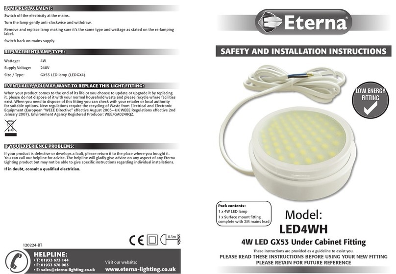
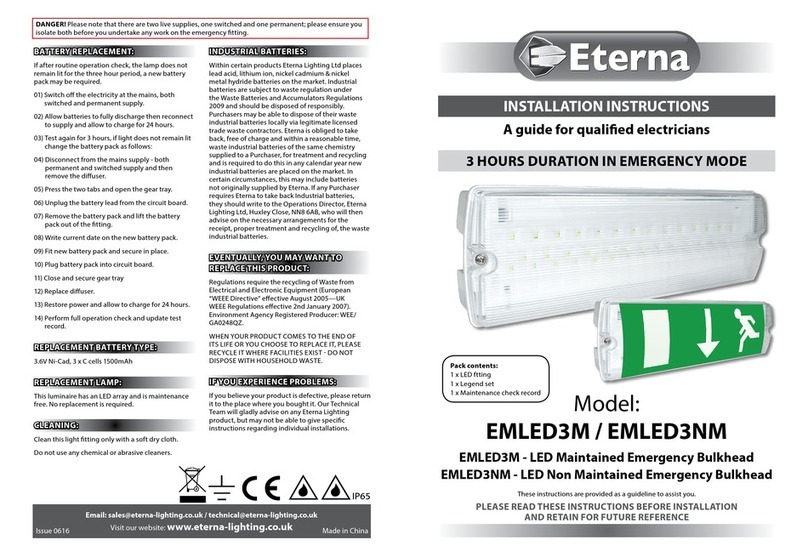
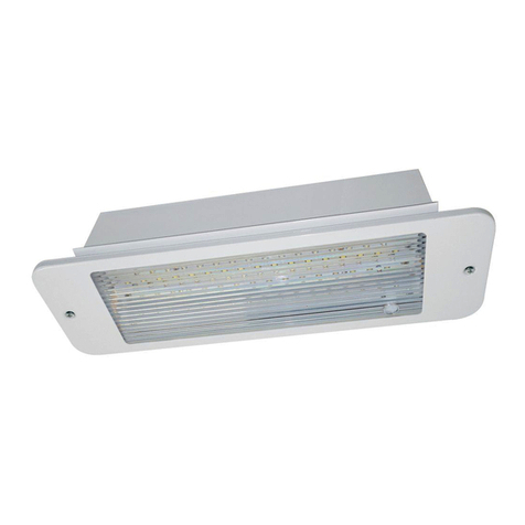
Check the pack and make sure you have all of the
parts listed on the front of this booklet. If not,
contact the outlet where you bought this product.
This product must be installed by a competent
person in accordance with the current building and
IEE wiring regulations.
As the buyer, installer and/or user of this product it
is your own responsibility to ensure that this tting
is t for the purpose for which you have intended
it. Eterna Lighting cannot accept any liability for
loss, damage or premature failure resulting from
inappropriate use.
This product is designed and constructed according
to the principles of the appropriate British Standard
and is intended for normal domestic service. Using
this tting in any other environments may result in
a shortened working life, for example where there
are prolonged periods of use or higher than normal
ambient temperatures.
Switch o the mains before commencing installation
and remove the appropriate circuit fuse or lock o
MCB.
This unit is suitable for outdoor use.
This product is designed for permanent connection
to xed wiring: this must be a suitable circuit
(protected with the appropriate MCB or fuse).
Before making xing hole(s), check that there are no
obstructions hidden beneath the mounting surface
such as pipes or cables.
Make sure that the xings are strong enough to
support the weight of the tting and hold it rigidly.
The chosen location of your tting should allow for
the product to be securely mounted and anchored to
a solid surface e.g. concrete, brick or a joist - do not
x directly onto panelling, cladding, plasterboard
etc.
This product must be connected to earth
termination.
Make connections to the electrical supply in
accordance with the following code:
Live – Brown or Red
Neutral – Blue or Black
Earth – Green and Yellow
When working at heights ensure you use a suitable
platform.
The lamp must be positioned so that there is at least
0.5m (500mm) between the bulb and any illuminated
surface.
This tting has a ferromagnetic ballast which might
cause a slight resonance perceivable at places with
good acoustics and/or where the mounting surface
is able to resonate with the ttings. In these unusual
circumstances, we recommend the use of high
frequency electronic control gear.
When making connections ensure that the terminals
are tightened securely and that no strands of wire
protrude. Check that the terminals are tightened
onto the bared conductors and not onto any
insulation.
WARNING: This product becomes hot!
This product is not intended to be used by children
and persons with sensory, physical and/or mental
impairments that would prevent them from using it
safely.
You are advised at every stage of your installation to
double-check any electrical connections you have
made. After you have completed your installation
there are electrical tests that should be carried out,
these tests are specied in the current IEE wiring and
building regulations.
INSTALLATION:
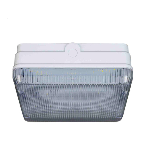
01) Loosen the two screws and lift o the front cover.
02) Remove the two screws that retain the reector
and lift it away.
03) Choose the position of the xing holes in the
back of the tting and clear through using a
suitably sized drill.
04) Using the back of the tting as a template,
mark o the position of the xing holes on the
mounting surface.
05) Choose the location of the cable entry (end or
rear) and make a suitably sized hole.
06) Peel o the wax paper backing from the large
square gasket (supplied) and stick it into the
square recess in the back of the tting over the
xing holes.
07) Fit either a rubber grommet or cable gland into
the hole.
08) If tting a grommet, pierce it but ensure that the
hole is not made too large so that a good,
water-tight seal is maintained around the cable.
Thread the supply cable in through the grommet.
If tting a cable gland, ensure that it is properly
tightened.
09) Using xings appropriate to the weight of the
tting and the mounting surface, secure the
tting in position.
10) Fit the heat-proof sleeving over the supply cable.
11) Connect the supply cable to the terminals inside
the tting according to the wiring code listed
opposite.
12) Secure the cable in the cable grip.
13) Re-t the reector and securely tighten the
screws.
14) Insert suitable energy saving lamp.
15) Replace the cover and secure in place. Ensure that
the gasket around the cover is intact and tted
correctly.
16) Restore the power and switch on.
