SICK RFH620-1001201S01 User manual

OPERATING INSTRUCTIONS
Special Version
RFH620-1001201S01
Radio Frequency Interrogator
(13.56 MHz)

Operating Instruction
RFH620
8013171/ZO93/2017-08-08 ©SICK AG •Germany •All rights reserved • Subject to change without notice 3
Software Versions
Software/Tool Function Version
RFH620-1001201S01 Firmware S 0.60
Copyright
Copyright © 2009 -2017
SICK AG
Erwin-Sick-Str. 1
79183 Waldkirch
Germany
Trademarks
WindowsTM is a registered trademark or trademark of the Microsoft Corporation in the
USA andother countries.
AdobeTM ReaderTM is a trademark of the Adobe Systems Incorporated.

Operating Instructions
RFI341 Radio Frequency Interrogator
48013171/ZO93/2017-08-08 ©SICK AG • Germany • All rights reserved • Subject to change without notice
Figures and Tables
Contents
1 Notes about this Document ................................................................................... 8
1.1 Purpose ...................................................................................................... 8
1.2 Target Groups............................................................................................ 8
1.3 Deep of information .................................................................................. 8
1.4 Symbols Used............................................................................................ 8
2 Safety Information............................................................................................... 10
2.1 Authorised User....................................................................................... 10
2.2 Intended use............................................................................................. 11
2.3 Electrical Connection and Replacement.................................................. 11
2.4 Start-up, Operation and Configuration .................................................... 11
2.2 General Safety Instructions and Protective Measures ............................. 12
2.3 Quick stop and quick restart .................................................................... 12
3.1.1 2.3.1 Switching off the RFH620...........................................................................12
3.1.2 2.3.2 Switching the RFH620 back on ...................................................................12
2.4 Environmental Conditions....................................................................... 12
3.1.3 2.4.1 Energy requirements....................................................................................13
3.1.4 2.4.2 Disposal of the device after decommissioning.............................................13
3 Product Description............................................................................................. 14
3.1 Setting up the RFH620 ............................................................................ 14
3.1.5 3.1.2 Device view .................................................................................................14
3.2 Included in delivery................................................................................. 16
3.1.6 3.2.1 Contents of the CD-ROM 2049555 .............................................................16
3.3 Device versions ....................................................................................... 16
3.4 System Requirements ...................................................................................... 17
3.5 Product features and functions (overview) ...................................................... 17
3.5 RFH620 method of operation .......................................................................... 18
3.5.1 Reading / Writing configuration...............................................................................19
3.5.2 Object trigger control ...............................................................................................19
3.5.3 Increment configuration ...........................................................................................19
3.5.4 ISO/IEC 15693 configuration ..................................................................................19
3.5.5 Reading operation mode (object related)..................................................................20
3.5.6 Data Processing........................................................................................................20
3.5.7 Output format...........................................................................................................21
3.5.8 Network / Interface / IOs..........................................................................................21
3.5.9 Data interfaces..........................................................................................................21
3.5.10 Digital Inputs..........................................................................................................21
3.5.11 Digital Outputs.......................................................................................................22
3.6 Indicators and control elements ....................................................................... 22
3.5.1 User Interface...........................................................................................................22
3.5.2 LEDs on the RFH620 housing .................................................................................23

Operating Instruction
RFH620
8013171/ZO93/2017-08-08 ©SICK AG • Germany • All rights reserved • Subject to change without notice 5
4 Installation............................................................................................................24
4.1 Overview of installation sequences..................................................................24
4.2 Installation preparations...................................................................................24
4.2.1 Components to be installed ...................................................................................... 24
4.2.2 Accessories .............................................................................................................. 25
4.2.3 Mounting device ...................................................................................................... 25
4.3 Installation location..........................................................................................26
4.4 Installation of the RFH620...............................................................................26
4.4.1 Installing the RFH620.............................................................................................. 26
5 Electrical Installation...........................................................................................27
5.1 Overview of installation sequences..................................................................27
5.2 Electrical installation preparation ....................................................................27
5.3 Electrical connections and cables.....................................................................28
5.3.1 Electrical connections .............................................................................................. 28
5.3.2 RFH620 connections................................................................................................ 28
5.3.2 RFH620 connections................................................................................................ 29
5.4 Performing electrical installation .....................................................................29
5.4.1 Connecting the power supply for the RFH620......................................................... 30
5.4.2 Wiring serial data interface ...................................................................................... 30
5.4.3 Wiring CAN interface.............................................................................................. 32
5.4.3 Wiring Ethernet interface......................................................................................... 32
5.4.4 Wiring switching inputs ........................................................................................... 32
5.5 Pin assignment and wire colour assignment of the assembled cables..............33
5.4.1 Pin assignment of the assembled cables................................................................... 33
5.4.2 Pin assignment of the assembled cables with an open end....................................... 34
6 Startup and configuration ...................................................................................35
6.1 Overview of the startup procedure...................................................................35
6.2 SOPAS-ET configuration software..................................................................35
6.2.1 Functions of the SOPAS-ET configuration software for the RFH620 ..................... 35
6.2.2 System requirements for the SOPAS-ET configuration software ............................ 35
6.2.3 Installing the SOPAS-ET configuration software .................................................... 36
6.2.4 Default setting for SOPAS-ET configuration software ............................................ 36
6.3 Establish communication with the RFH620.....................................................36
6.3.1 Connecting data interface......................................................................................... 36
6.3.2 Starting the SOPAS-ET configuration software....................................................... 37
6.3.3 Starting the SOPAS-ET configuration software....................................................... 38
6.3.4 Carrying out a scan .................................................................................................. 38
6.4 First startup ......................................................................................................39
6.4.1 Overview of the startup procedure ........................................................................... 39
6.4.2 Configure the RFH620............................................................................................. 40
6.4.3 Permanently load changed parameter sets into the device ....................................... 41
6.4.4 Save, display and print the current parameter set..................................................... 41
6.5 Default settings ................................................................................................41
6.5.1 Resetting the default setting in the RFH620 ............................................................ 41

Operating Instructions
RFI341 Radio Frequency Interrogator
68013171/ZO93/2017-08-08 ©SICK AG • Germany • All rights reserved • Subject to change without notice
Figures and Tables
7 Maintenance during operation ........................................................................... 43
7.1 Checking the incremental encoder................................................................... 43
7.2 Replacing RFH620 .......................................................................................... 43
7.2.1 Removing the RFH620 ............................................................................................43
7.2.2 Replacing the RFH620.............................................................................................43
8 Troubleshooting................................................................................................... 44
8.1 Overview of errors and malfunctions which could occur ................................ 44
8.1.1 Installation error.......................................................................................................44
8.1.2 Electrical installation error .......................................................................................44
8.1.3 Configuration error...................................................................................................44
8.1.4 Malfunctions during operation .................................................................................44
8.2 Detailed malfunction analysis.......................................................................... 44
8.2.1 LEDs on the RFH620...............................................................................................44
8.2.2 System information ..................................................................................................45
8.3 Status protocol ................................................................................................. 45
8.3.1 Displaying the status protocol using the SOPAS-ET configuration software ..........45
8.4 SICK Support .................................................................................................. 45
9 Technical Data ..................................................................................................... 46
9.1 Datasheet of RFH620 RFID device ................................................................. 46
9.2 Reading Diagrams ........................................................................................... 47
9.3 RFH620 dimensional drawings ............................................................... 47
10 Appendix .............................................................................................................. 48
11.1 Appendix overview........................................................................................ 48
11.2 Configuration the RFH620 with command strings ........................................ 48
11.3 Order information for the RFH620 and the accessories ................................ 49
11.3.1 Order information for the RFH620 RFID device ...................................................49
11.3.2 Accessories: Mounting devices ..............................................................................49
11.3.3 Accessories: Connection modules..........................................................................49
11.3.3 Accessories: cables for Ethernet Version ...............................................................51
11.3.4 Accessories: ISO/IEC 15693 compliant Transponder ............................................52
11.3.5 Accessories: SD Card.............................................................................................52
11.4 Dimensional drawing accessories.................................................................. 53
11.4.1 Dimensional drawing fixing bracket no. 2048551..................................................53
11.5 Glossary......................................................................................................... 53
11.6 EC Declaration of Conformity....................................................................... 54

Operating Instruction
RFH620
8013171/ZO93/2017-08-08 ©SICK AG • Germany • All rights reserved • Subject to change without notice 7
Tables & Figures
Table 2-1 Required qualification for starting up the RFH620........................................10
Table 3-1: Variant of the RFH620.............................................................................14
Table 3-2: Device view of the RFH620 (Ethernet version).......................................15
Table 3-3: RFH620 delivery......................................................................................16
Table 3-4: Variants of the RFH620 ...........................................................................16
Table 3-5: Overview of the RFH620 product features and functions........................17
Figure 3-6: HF Technology – principle overview ......................................................18
Figure 3-7: Methods of operation in a conveyor system.............................................18
Figure 3-8: reading operation mode for the RHF620 in stand-alone operation ..........20
Table 3-9: data interface function..............................................................................21
Table 3-10: LED indications .................................................................................23
Table 4-1: Example: Fixing the RFH620 with the angle with adapter plate no.
2048551 25
Table 5-1: Ethernet version: Electrical connections at the RFH620 with connector
unit 28

Chapter 1Operating Instructions
Radio Frequency Identification RFI341 Interrogator
88013171/ZO93/2017-08-08 © SICK AG • Germany • All rights reserved • Subject to change without notice
Notes On This Document
1Notes about this Document
1.1 Purpose
This document provides instructions for technical staff on the installation and operation
of the RFID special device RFH620 with two integrated LED’s in the front side:
This document contains information about:
•Mounting and electrical installation
•Start-up
•Use and configuration
•Replacing
A step-by-step approach is taken for all tasks.
1.2 Target Groups
The target groups for this user guide are:
•Operating electricians
•Technicians and engineers
1.3 Deep of information
This document contains all the required information for installation, electrical
installation and operation of the RFID device at the installation location. The factory
default setting (basic configuration) of the RFID device is prepared for the use as a
stand-alone device. Configuration of the RFID device for the application-specific
reading conditions and operation is carried out using the SOPAS-ET configuration
software on a WindowsTM PC, or – if available – via an external middleware. The
SOPAS-ET configuration software contains an online help system to facilitate
configuration.
1.4 Symbols Used
To gain easier access, some information in this documentation is emphasised as follows:
NOTICE!
Warnings are provided to prevent injury to operating personnel or serious damage to the
RFID Interrogator.
¾Always read warnings carefully and observe them at all times.
A
TTENTION

Operating Instructions Chapter 1
RFI341
8013171/ZO93/2017-08-08 ©© SICK AG • Germany • All rights reserved • Subject to change without notice 9
Notes On This Document
Warning notice!
A warning notice indicates real or potential danger. This should protect you against
accidents. The safety symbol next to the warning notice indicates why there is a risk of
accident, e.g. due to electricity. The warning levels (DANGER, WARNING,
CAUTION) indicate the seriousness of the risk.
¾Carefully read and follow the warning notices!
Note Notes provide information on special features or characteristics.
Explanation Explanations provide background information on technical aspects.
Recommendation Recommendations provide advice on how to carry out a task more effectively
This symbol refers to additional technical documentation.
WARNING

Chapter 2Operating Instructions
Radio Frequency Identification RFI341 Interrogator
10 8013171/ZO93/2017-08-08 © SICK AG • Germany • All rights reserved • Subject to change without notice
Safety Information
2Safety Information
This chapter deals with your safety and operator safety in the operational area.
¾Read this chapter carefully before using the RFID device.
2.1 Authorised User
For correct and safe functioning, the RFID device must be installed, operated and
maintained by sufficiently qualified staff.
Repairs to the RFID device should only be carried out by qualified and authorised SICK
service staff.
¾The operating instructions should be made available to the end user.
¾The end user should be briefed and urged to read the operating instructions by the
technicians.
The following qualifications are required for different activities:
Task Qualification
Installation,
maintenance
¾Practical technical training
¾Knowledge of current health and safety regulations at
the workplace
Electrical installation,
device replacement
¾Practical electrical training
¾Knowledge of current electrical safety regulations
¾Knowledge of start-up and operation of the device in
each operational
¾area (e. g. conveyor system)
Startup, configuration ¾Basic knowledge of the WindowsTM operating system
¾Basic knowledge of designing and setting up
(addressing) Ethernet
¾connections for connecting the bar code system to the
Ethernet
¾Basic knowledge of working with an HTML browser (e.
g. Internet ExplorerTM) for using the online help
¾Basic knowledge of data transfer
¾Basic knowledge of bar code technology
Operation of the device
in each operational area
¾Knowledge of start-up and operation of the device in
each operational area (e. g. conveyor system)
¾Knowledge of the software and hardware environment
in each operational area (e. g. conveyor system)
Table 2-1 Required qualification for starting up the RFH620

Operating Instructions Chapter 2
RFH620
8013171/ZO93/2017-08-08 ©SICK AG • Germany • All rights reserved • Subject to change without notice 11
Safety Information
2.2 Intended use
The RFH620 RFID device is an intelligent sensor for the automatic recognition and
decoding of 13.56 MHz, ISO 15693 compliant RFID transponder signals e.g. placed on
objects in a conveyor system.
The RFID device enable the bi-directional communication with a host for, e.g., further
processing.
The intended use of the RFID device results from the following description of the
function:
¾In a reading station/situation the RFH620 could be installed in a holder, either on
the side of a conveyor system (side reading) or under it (reading from below)
¾In a writing station/situation the RFH620 gets the date to be written from the host
system
¾The LED’s in the front antenna panel could be switch by either the system
depending on the reading result or by the host via command language.
¾The RFID device transfers the reading data via the host interface to a superordinate
host computer for further processing.
¾The RFH620 could be configured/operated using the SOPAS-ET configuration
software that runs on a standard client PC provided by the customer or via
command language. Communication takes place using RS-232 or Ethernet.
Any warranty claims against SICK AG shall be deemed invalid in the case changes to
the RFH620, such as opening the housing, this includes modifications during
installation and electrical installation or changes to the SICK software.
2.3 Electrical Connection and Replacement
•Practical training in electrical technology
•Knowledge of the standard safety guidelines relating to electrical technology
•Knowledge regarding the operation of the devices in the relevant application (e.g.
conveyor belt)
2.4 Start-up, Operation and Configuration
•Knowledge regarding the operation of the devices in the relevant application (e.g.
conveyor belt)
•Knowledge of the software and hardware environment of the relevant application
•Basic understanding of data transfer methods
•Basic understanding of RFID technology

Chapter 2Operating Instructions
Radio Frequency Identification RFI341 Interrogator
12 8013171/ZO93/2017-08-08 © SICK AG • Germany • All rights reserved • Subject to change without notice
Safety Information
2.2 General Safety Instructions and Protective Measures
Read carefully the general safety instructions and observe them at all times. This also
applies to the warnings provided for the activities described in each chapter of this
document.
2.3 Quick stop and quick restart
The RFH620 can be switched on or off using the main switch for connection modules
CDB620 or CDM420.
3.1.1 2.3.1 Switching off the RFH620
¾Switch off the power supply to the RFH620 (the connection module)
- or -
¾Remove (pull out) the 15-pole D-Sub-HD connector of the RFID device
When the RFH620 is switched off, the following data is lost:
¾Application-specific parameter sets in the bar code scanner that were only saved
temporarily in the device
¾The last reading result of the bar code scanner
¾Daily operating hours counter of the RFH620
3.1.2 2.3.2 Switching the RFH620 back on
¾Switch on the power supply to the RFH620 (the connection module) back on
- or -
¾Connect the 15-pole D-Sub-HD connector of the RFH620
The RFH620 starts up using the most recent permanently saved configuration. The
daily operating hours counter is reset.
2.4 Environmental Conditions
The RFI341 is designed to cause minimum impact to the environment.

Operating Instructions Chapter 2
RFH620
8013171/ZO93/2017-08-08 ©SICK AG • Germany • All rights reserved • Subject to change without notice 13
Safety Information
3.1.3 2.4.1 Energy requirements
The RFH620 consumes typically < 4,5W with 24V DC ±10%.
3.1.4 2.4.2 Disposal of the device after decommissioning
SICK AG will not currently accept the return of any devices which can no longer be
operated or repaired.
-Inoperable or irreparable devices must be disposed of in an environmentally
friendly manner and in accordance with valid country-specific waste disposal
guidelines.
The design of the RFID device allows for its separation as recyclable secondary raw
materials and hazardous waste (electronic scrap).

Chapter 10 Operating Instructions
Radio Frequency Identification RFH620 Interrogator
14 8013171/ZO93/2017-08-08 © SICK AG • Germany • All rights reserved • Subject to change without notice
Appendix
3 Product Description
This chapter describes the design, the features and the functions of the RFH620 RFID
device. The RFID works at a frequency of 13.56 MHz and reads passive ISO/IEC
15693 tags.
¾For installation, electrical installation and startup assistance as well as for the
application specific configuration of the RFH620 using the SOPAS-ET
configuration software, please read this chapter prior to carrying out any of the
tasks.
3.1 Setting up the RFH620
The RFH620 consists of an integrated antenna and an electronic unit with an integrated
decoder. The RFID field enters via the black top plastic part of the housing. The
RFH620 (depending on the version) is electrically connected by a revolving connector
unit with two connections.
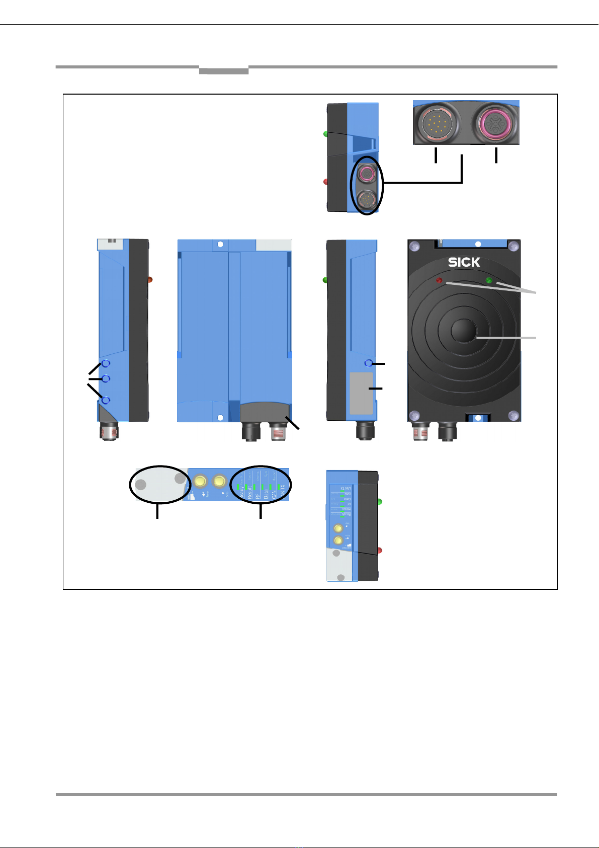
3.1.5 3.1.2 Device view
Table 3-1: Variant of the RFH620
Operating Instructions Chapter 10
RFI341
8013171/ZO93/2017-08-08 ©SICK AG • Germany • All rights reserved • Subject to change without notice 15
Appendix
Table 3-2: Device view of the RFH620 (Ethernet version)
1
1
2
3
4
5
6
78
1 – Blind hole taps M6
2 – Type plate
3 – LEDs for status indicator
4 – Antenna
5 – LEDs for signaling
6 – Revolving connector unit
7 – 12-pole M12 plug
8 – 4-pole M12 jack (Ethernet IF)
9 – Opening for SD card
9

Chapter 10 Operating Instructions
Radio Frequency Identification RFH620 Interrogator
16 8013171/ZO93/2017-08-08 © SICK AG • Germany • All rights reserved • Subject to change without notice
Appendix
3.2 Included in delivery
Delivery of the RFH620 includes the following components:
Pieces Components Comment
1 RFID Device RFH620
1 Notes on device with electrical
connection diagram as primary
information
Included in the device packaging of
the RFH620
1 CD-ROM "Manuals & Software
Auto Ident"
SICK Order No. 2049555
Table 3-3: RFH620 delivery
An overview of in-stock installation accessories, connection modules, cables and
connectors as well as sensors for reading pulses is available in chapter “Ordering
information for RFH620.
3.1.6 3.2.1 Contents of the CD-ROM 2049555
¾"SOPAS-ET Engineering Tool“: Configuration software for WindowsTM PCs with
integrated online help system (HTML files)
¾RFH620 operating instructions: PDF version in English
¾“Acrobat Reader“: Freely available PC software for reading PDF files
The current versions of publications and programs on the CD-ROM can also be
downloaded at www.sick.com.
3.3 Device versions
Delivery of the RFH620 includes the following components:
Type Order No. Description
RFH620-1001201S01 1046849 RFID device for proximity read range (up to 16cm) with
two in antenna plate integrated LEDs
Table 3-4: Variants of the RFH620

Operating Instructions Chapter 10
RFI341
8013171/ZO93/2017-08-08 ©SICK AG • Germany • All rights reserved • Subject to change without notice 17
Appendix
3.4 System Requirements
General system requirements are derived from the RFH620 technical data (see chapter
“Technical data”).
The requirements and conditions for Installation, electrical installation and “startup and
configuration” are summarised in the respective chapters.
3.5 Product features and functions (overview)
RFH620 RFID device ¾supports ISO/IEC 15693 (18000-3M1) compliant transponder ICs (mandatory and optional
command set)
¾Reading direction to front side
¾Large reading area to address high speed applications
¾International radio approval (CE&FCC)
User safety and convenience ¾Robust, compact metal housing, CE/FCC mark
¾Automatic self-test on system startup
¾Diagnosis tools for system setup and system (remote) monitoring
¾Operational data retrieval, error code display on request in case of errors
¾Activatable test string function (heartbeat) for signalling readiness for operation
¾Password protected configuration mode
¾Future proof due to firmware update (flash PROM) via data interface
¾Future-proof SOPAS-ET configuration software
¾Extended power supply range
Convenient operation/configuration ¾Configuration (online/offline) using the SOPAS-ET configuration software (incl. Help
system)
¾Status indicators via five LEDs
¾Beeper that can be switched off to confirm device functioning
Reading operation modi ¾Start/Stop operation
¾Free running reading method
Reading pulse ¾Pulse sources for start: switching inputs; data interface (command); automatic cycle; CAN
¾Pulse sources for stop: reading pulse source, switching inputs, command, timer, condition
Data processing ¾Manipulation of the output of the reading data via event-dependent evaluation conditions
¾Manipulation of the output strings through filter and output sort options
¾Switching the outputs via interface command language
Data communication ¾Host interface: two data output formats configurable, switchable to different physical
interfaces, parallel operation possible
¾Aux interface: fixed data output format, switchable to different physical interfaces, parallel
operation possible
Electrical interfaces ¾Host interface: RS-232, RS-422/485 (data format and protocol can be configured) and
Ethernet, or CAN
¾Aux interface: RS-232, (fixed data format, data transfer rate and protocol) and Ethernet
¾CAN interface for integration into the SICK-specific CAN-SENSOR network
¾One digital switching input on the device
¾Digital switching outputs connected with LEDs in front side
Connection technology (design) ¾Revolving connector unit on the device with two M12 circular connectors
¾Connection module CDB620/CDM420 for connection to the host computer (standalone)
and for integrating into the SICK-specific CAN-SENSOR network
¾Bus connection module CMF4001) in connection module CDM420 for connecting to field
bus systems
Table 3-5: Overview of the RFH620 product features and functions

Chapter 10 Operating Instructions
Radio Frequency Identification RFH620 Interrogator
18 8013171/ZO93/2017-08-08 © SICK AG • Germany • All rights reserved • Subject to change without notice
Appendix
3.5 RFH620 method of operation
The RFH620 is an intelligent sensor system for automatic and non-contact detection and
decoding of SISO/IEC15693 compliant transponders. In principle, the transponders can
be detected on any side of still or moving objects in a conveyor system. Several RFID
devices can be combined to allow detection of several sides in one passage (multi-side
reading).
The RFH620 creates a high frequency field to recognise transponders. The transponder
itself generate out of the field the power for operation and the data send from the RFID
device and respond data to the interrogator using field load modulation. The size of the
reading field depends mainly on the used transponder (size and Q-factor) and the
environment (metal objects).
Figure 3-6: HF Technology – principle overview
To control a process, external sensors could deliver information via the reading pulse,
the object distance and the conveyor speed (increment). The reading/writing results are
output to the RFH620 data interfaces and forwarded to a host/PC.
Figure 3-7: Methods of operation in a conveyor system

Operating Instructions Chapter 10
RFI341
8013171/ZO93/2017-08-08 ©SICK AG • Germany • All rights reserved • Subject to change without notice 19
Appendix
3.5.1 Reading / Writing configuration
The RFH60 is compliant with the ISO 15693 Standard. Via SOPAS tool standard
specific setting could be set.
In addition parameters could be set that e.g could be used to define reading window
conditions as well as conditions for the actions to be taken within.
3.5.2 Object trigger control
In order to start an object-related reading process, the RFH620 requires an appropriate
external signal (trigger source) for reporting an object in the reading area. The start
signal is emitted via an external reading pulse sensor (e. g. photoelectric reflex switch)
as standard. As soon as an object has passed the reading pulse sensor, a time window
opens in the RFH620 (“reading/writing gate“) for the reading/writing process.
Alternatively, a command activates the reading process via a data interface or the CAN-
SENSOR network. In Automatic mode, the RFID device generates the reading gate
internally with an adjustable mark-space ratio.
The reading pulse can be ended in a number of ways: With external triggering by the
reading pulse source or a command, internally by a timer or an evaluation condition to
be met.
The trigger source could be configured using the SOPAS-ET configuration software:
PROJECT TREE, RFH620, PARAMETER, READING CONFIGURATION, OBJECT
TRIGGER CONTROL, register tab START/STOP OF OBJECT TRIGGER
3.5.3 Increment configuration
The RFID device receives information about the conveyor speed from an external
incremental encoder, for example. The incremental encoder delivers pulses which are
used to determine the current conveyor speed.
The conveyor speed results from the number of impulses and the resolution of the
external incremental encoder.
The increment source and the resolution/speed can be configured using the SOPAS-ET
configuration software: PROJECT TREE, RFH620, PARAMETER, INCREMENT
CONFIGURATION, register tab INCREMENT
3.5.4 ISO/IEC 15693 configuration
The RFH620 is compliant with the ISO 15693 Standard. All mandatory and optional
command set as defined in the standard are supported. All transponders that comply full
with the standard could be used in a customer application. A actual list of supported
transponder IC’s could be requested via SICK sales channel.

Chapter 10 Operating Instructions
Radio Frequency Identification RFH620 Interrogator
20 8013171/ZO93/2017-08-08 ©SICK AG •Germany •All rights reserved
Appendix
3.5.5 Reading operation mode (object related)
There is only one object in the reading field during start/stop operation, i.e. all the read
data should be unambiguously assigned to the object. The start and stop of the reading
process control one/two reading pulse sensors at the beginning and at the end of the
reading field as standard. The distance between each sensor is determined by the size of
the reading field. The reading process can be alternatively controlled with command
strings via the data interface. The output of the reading results is carried out either at the
end of the reading pulse (the rear edge of the object has left the end of the reading field)
or during the reading pulse if certain configurable conditions have been fulfilled.
Figure 3-8: reading operation mode for the RHF620 in stand-alone operation
The reading operation mode can be configured using the SOPAS-ET configuration
software: PROJECT TREE, RFH620, PARAMETER, DATA PROCESSING, register
tab TRACKING
3.5.6 Data Processing
The output time in the reading process with regard to the reading pulse start can be
configured using the SOPAS-ET configuration software: PROJECT TREE, RFH620,
PARAMETER, DATA PROCESSING, OUTPUT CONTROL
Furthermore, the evaluation conditions and filters and sorters for data output to the host
computer can be configured: PROJECT TREE, RFH620, PARAMETER, DATA
PROCESSING, EVALUATION CONDITION
PROJECT TREE, RFH620, PARAMETER, DATA PROCESSING, FILTER/SORTER
FOR OUTPUT

Operating Instructions Chapter 10
RFI341
8013171/ZO93/2017-08-08 ©SICK AG •Germany •All rights reserved 21
Appendix
3.5.7 Output format
The reading result (decoded codes) is displayed via selectable physical interfaces. Two
different output formats (telegrams) can be defined for this task, one format for "No
Read" and one for the heartbeat (signalisation of readiness).
Note The output formats can be configured using the SOPAS-ET configuration
software: PROJECT TREE, RFH620, PARAMETER, DATA PROCESSING,
OUTPUT FORMAT
3.5.8 Network / Interface / IOs
All important interfaces for displaying the reading results are available on the RFH620.
Several RFID devices can be connected to each other via the CAN bus in the SICK-
specific CAN-SENSOR network.
The network parameters can be configured using the SOPAS-ET configuration
software: PROJECT TREE, RFH620, PARAMETER, NETWORK / INTERFACE /
IOS, tab pages NETWORK OPTIONS
3.5.9 Data interfaces
The following data interfaces are available on the RFH620:
Data interface Function
Host interface
(RS-232 or RS-422/485
and Ethernet host port)
¾Preparation of the reading result for further
processing by the host processor
Auxiliary interface (RS-232
and Ethernet aux port)
¾Reading diagnosis or host interface monitoring
CAN ¾Networking several bar code scanners
Table 3-9: data interface function
The data interfaces can be configured using the SOPAS-ET configuration software:
PROJECT TREE, RFH620, PARAMETER, NETWORK / INTERFACE / IOS,
SERIAL
PROJECT TREE, RFH620, PARAMETER, NETWORK / INTERFACE / IOS,
ETHERNET
PROJECT TREE, RFH620, PARAMETER, NETWORK / INTERFACE / IOS, CAN
3.5.10 Digital Inputs
The external sensor for the object triggering (photoelectric reflex switch) and the
incremental encoder, e.g., can be connected to the digital switching inputs.
The digital inputs can be configured using the SOPAS-ET configuration software:
PROJECT TREE, RFH620, PARAMETER, NETWORK / INTERFACE / IOS,
DIGITAL INPUTS
Table of contents
Other SICK Other manuals


Popular Other manuals by other brands


Bavarian Demon
Bavarian Demon AXON Product information

Aqua Medic
Aqua Medic CO2 reactor+ Operation manual

Alfalaval
Alfalaval Toftejorg MultiJet 65 instruction manual

Aqua Medic
Aqua Medic Kauderni CF Operation manual

NewLine
NewLine Anita instruction manual

Alfalaval
Alfalaval Gunclean Toftejorg T-82 instruction manual

ALLOMATIC
ALLOMATIC TK-1000 Hardware installation instructions

Advanced Card Systems
Advanced Card Systems ACR321 user manual

Perfect Aire
Perfect Aire 4PADP95 user manual

Night Stick
Night Stick XPP-5462GX Dicata instruction manual

Aqua Medic
Aqua Medic Light Computer Operation manual

globalwater
globalwater FL16 user manual