Siegen tools S0825 User manual

Shade active: ..................9 - 13 variable
Shade inactive:.................4
Viewing area...................98 x 48
Response time (light to dark) ......0.1ms
Operating temperature ...........-5°C to +55°C
Storing temperature .............-20°C to +70°C
Power ........................Solar Cells
weight ........................420g
Welding helmet with infinitely adjustable shade control between 9 and 13. Complies with CE & DIN Standards.
Fully automatic switching from light to dark on striking arc. Shade is selected by large rotary knob on side of
helmet. Solar panel power supply - no batteries required. Features sensitivity and delay controls for switching
light to dark. Deluxe contured helmet with fully adjustable headband with front pad for added comfort. Suitable for
MIG, TIG and ARC Welding.
The S0825 Automatic Welding Helmet comes ready for use. Batteries are not necessary as operation is by means
of Solar cells which automatically darkens the eye shade cartridge when the arc is struck.
1. SAFETY INSTRUCTIONS
3 Ensure all workshop safety rules, regulations, and conditions are complied with when using welding equipment.
7The helmet will not offer protection against mis-use of workshop tools, equipment, or accessories.
3 Maintain the helmet in good condition, and protect cartridge from liquid and dirt contact.
3 Regularly replace the protective lenses and replace any damaged or worn parts. Use genuine parts only.
7 Non authorised parts may be dangerous and will invalidate the warranty.
7 NEVER open or tamper with the shade cartridge.
WARNING! This helmet is not suitable for use with laser and gas-welding.
3 Ensure the front cover lens and front lens frame are securely in place
before use.
3 Select the shade level before use.
3 Fit the helmet and adjust the head band so the helmet will sit as low and
near to your face as possible,
3 Use helmet only in temperatures ranging from -5°C to + 55°C .
7 The eye protective plate in helmet is NOT unbreakable. Helmet will not
protect you against severe impact hazards (such as, but not limited to)
fragmenting abrasive discs/grinding wheels, stones and other grinding
tools, explosive devices or corrosive fluids. The helmet will only protect the
eyes and face from radiation and sparks.
3 Remove ill fitting clothing, remove ties, watches, rings, and other loose
jewellery.
3 Maintain correct balance and footing. Ensure the floor is not slippery and wear non slip shoes.
3 Keep children and unauthorised persons away from the working area.
WARNING! DO NOT use the helmet if damaged or you suspect it may be faulty. (Contact Service Agent).
7 DO NOT use helmet unless you have been instructed in its use by a qualified person.
7 DO NOT get the helmet wet or use in damp or wet locations.
7 DO NOT leave work place with helmet in lowered position, as bright light source may darken cartridge unexpectedly.
7 DO NOT place the helmet on a hot surface.
3 Clean helmet (see chapter 6) and store the helmet in a safe, dry, childproof location.
DANGER! If, at any time, the face plate in the cartridge FAILS to darken when exposed to a welding
spark, DO NOT USE. Remove cartridge and return to your dealer for service/inspection. Continued
use of the product knowing that the auto darkening feature is not functioning may damage your eyes
and cause blindness. Continued use of the helmet which is not functioning will invalidate the
warranty and could prohibit a successful claim on any insurance policy.
3. SPECIFICATION
2. INTRODUCTION
INSTRUCTION MANUAL
WELDING HELMET
SOLAR POWERED 9 - 13 SHADES
Thank you for purchasing a Siegen Tools product. Manufactured to a high standard this product will, if used according to these
instructions
and properly maintained, give you years of trouble free performance.
IMPORTANT: PLEASE READ THESE INSTRUCTIONS CAREFULLY. NOTE THE SAFE OPERATIONAL REQUIREMENTS, WARNINGS AND
CAUTIONS. USE THIS PRODUCT CORRECTLY AND WITH CARE FOR THE PURPOSE FOR WHICH IT IS INTENDED. FAILURE TO DO SO
MAY CAUSE DAMAGE AND/OR PERSONAL INJURY AND WILL INVALIDATE THE WARRANTY. RETAIN INSTRUCTIONS FOR FUTURE USE.
MODEL NO:
S0825
NOTE: It is our policy to continually improve products and as such we reserve the right to alter data, specifications and component parts without prior notice.
IMPORTANT: No liability is accepted for incorrect use of this equipment. WARRANTY: Guarantee 12 months from purchase date, proof of which will be required for any claim.
Declaration of Conformity We, the sole UK importer, declare that these products listed below are in conformity with the following standards and
The construction files for these products
are held by the Manufacturer and
may be inspected, by a national authority,
upon request to The Siegen Tool Co.
WELDING HELMET Solar Powered 9 - 13 Shade
MODEL: S0825
93/68/EEC CE Marking Directive
BS EN 175:1997 BS EN 379:1994
BS EN 169:2002
Signed by Steve Buckle
Sole UK Distributor, The Siegen Tool Co., Bury St. Edmunds, Suffolk E-mail: [email protected]
11th September 2008
Item No: Part No: Part description
1 S0825.01 Front Cover (Frame)
2 S0825.02 Front Cover Lens
3 S0825.03 Helmet
4 S0825.04 Knob for Potentiometer
5 S0825.05 Auto-darkening cartridge
Item No: Part No: Part description
6 S0825.06 Headband pivot bolts
7 S0825.07 Locating plate
8 S0825.08 Headband adjusting knob
9 S0825.09 Foam pad for headband
10 S0825.10 Adjustable headband
7. PARTS LIST & ASSEMBLY
CARTRIDGE
The cartridge is powered
by solar cells together with
two 3 volt lithium back up
batteries. No
battery changing is
necessary. Under normal use
the batteries have a lifetime
of more than 3 years.
fig 1
S0825 Issue No:1 12/09/08
IMPORTANT: This auto darkening welding helmet is designed to protect the eyes and face from spark, spatter
and harmful radiation under normal welding conditions. NOTE: The helmet comes ready assembled.
WARNING! Ensure that you have read and understood section 1. SAFETY INSTRUCTIONS.
4.1 Check that the front lens cover and retaining frame are securely in place. See 'N & P' in fig.4.
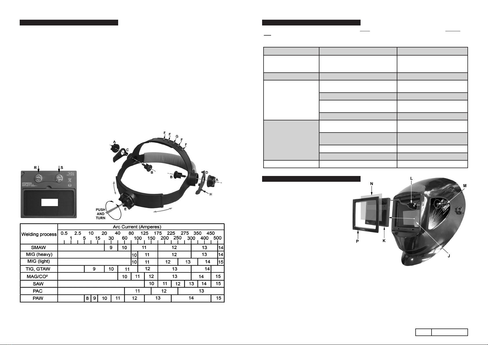
4.2 Select the shade level you require according to the welding process you will use by referring to the
“Selection Chart” below for settings. Turn the potentiometer control on the side of the helmet to the
number required. See 'M' in fig.4.
4.3 Adjust the switching time of the shade cartridge (the time it will take for the shade to turn from light to
dark and dark to light) by means of the delay control inside the helmet. See 'S' in fig.2. Again, adjust
the time according to the welding process you will use, in order to protect your eyes against the residual
light of the after glow or work materials. See technical data for response times.
4.4 Adjust the headband strap that passes over the head so that the helmet is seated on the head as low
as possible. See fig.3. Snap the spigot 'G' on the lower strap into one of the holes 'F' on the upper strap.
4.5 Adjust the size of the headband by using the ratchet knob at the rear (see 'E' in fig.3). Depress and turn
the knob until the headband sits firmly in place, but not too tight.
4.6 Use the two knobs 'A' on either side of the helmet to adjust the amount of friction that occurs as you
raise and lower the helmet.
4.7 When the helmet is in the lowered position, adjust its relationship to your face using the locating plate
'D' seen in fig.3. The spigot 'H' should be placed in one of 3 holes on the other side of the helmet from
the shade control knob.
4.8 The distance from each eye to the shade cartridge can also be adjusted by loosening the knobs
'A' and sliding the plastic bolts
'B' within the slotted openings
either side of the helmet.
4.9 You are now ready to use the
helmet. The shading may be
adjusted during use by re-setting
the shade control knob.
6.1 Replacing front cover lens. (See 'N' in
fig.4.) Firstly remove the front frame which is
held in place by four pairs of legs which pass
through four slots in the front recess. Reach
into the back of the helmet and release each
pair of legs in turn by squeezing the legs
together and pushing them forwards. Once
the frame is removed you can lift out the
front cover lens and place a new one into the
recess designed for it. Refit front frame and
press into place.
6.2 Replacing inside cover lens. (See 'J' in
fig.4.)The inside cover lens is located within
the back of the shade cartridge. There is a
finger access point along the top edge of the
cover. Pull the top edge of the lens away
from the cartridge until the top corners
release then lift the lens out. Locate the short
edge of the new lens in one side of the cartridge recess. Flex the material upwards until the other end can be
snapped into place.
6.3 Changing the shade cartridge. Loosen the grub screw in the side of the shade control knob 'M' and remove
the knob. Undo the nut which retains the potentiometer 'L' and remove the nut and washer, allowing the
potentiometer to hang loose within the helmet. Remove the front frame and lens cover as described above.
Place your hand over the cartridge opening and tip the helmet forwards allowing the cartridge to fall into
hand. Drop the new cartridge into the recess followed by the lens cover and snap the front frame into place.
Refix the potentiometer to the side of the helmet and refix the knob.
6.4 Cleaning. Clean the helmet by wiping with a soft clean cloth. Clean the cartridge surfaces with a lint free
cloth or tissue. Do not use any chemicals for cleaning purposes.
6.5 Sweat Band. Regularly remove the sweat band wash and replace.
4. INSTRUCTIONS FOR USE 5. PROBLEM SOLVING
DANGER! If, at any time, the face plate in the cartridge FAILS to darken when exposed to a welding spark, DO NOT
USE. Remove cartridge and return to your dealer for service/inspection. Continued use of the product knowing that the
auto darkening feature is not functioning may damage your eyes and cause blindness. Continued use of the helmet which
is not functioning will invalidate the warranty and could prohibit a successful claim on any insurance policy.
PROBLEM CAUSE REMEDY
Irregular darkening/dimming Headband has been set unevenly and
there is an uneven distance from the
eyes to the lter's lens.
Reset headband so that each eye is
the same distance from the lens.
Slow response Operating temperature is too low Do not use at temperature below -5°
Auto-darkening lter does
not darken or ickers
Sensitivity set too low Turn the sensitivity knob to 'HI'
position. See 'R' in g.2.
Front cover lens is soiled or damaged Change lens cover
Sensors are dirty Clean surface with lint free cloth/
tissue
Welding current is too low Reassess welding current
Poor vision Protective lm on front cover lens is not
peeled off.
Remove lm
Front/inside cover lens and/or lter lens
are dirty
Change lens
Insufcient ambient light. Increase light source
Shade number is incorrectly set Reset the shade number.
Welding helmet Slips Headband is not properly adjusted Readjust headband
fig 2
fig 3
6. MAINTENANCE
fig 4
SMAW ....................Shielded metal arc welding
MIG.........................(heavy) MIG on heavy metals
MIG ........................(light) MIG on light alloys
TIG, GTAW .............Gas tungsten arc welding
MAG/CO²................Metal active gas welding
SAW.........................Shielded semi-automatic welding
PAC ........................Plasma arc cutting
PAW........................Plasma arc welding
S0825 Issue No:1 12/09/08
Other Siegen tools Welding Accessories manuals


