sieger Drain-Jet S User manual
READ THIS MANUAL BEFORE USING THIS MACHINE
EN
Sieger Drain-Jet S
Sieger Drain-Jet HS
Sieger Drain-Jet WR
www.sieger-machinery.com
USER MANUAL

2112202RE101_A_M
EN
Sieger
Handelsstraat 36 b
7482GW Haaksbergen
The Netherlands
(+31 (0)53 – 303 12 65
@ info@sieger-machinery.com
ü www.sieger-machinery.com
Copyright ©
All rights reserved. No part of this publication may be duplicated, stored in an automated retrieval
system, or published in any form or by any means, be it electronic, mechanical, photocopying,
photography, recording or otherwise, without the prior written permission of Sieger.
Changes
This publication is based on the most recent information available at the time of publication.
Because Sieger pursues a policy of continuous product improvement, this publication may be
changed without prior notice.
Liability
This publication has been prepared with the greatest possible care. Nevertheless, it may not
be entirely accurate. Sieger accepts no liability for any errors in this publication or the possible
consequences thereof.
Language
Original manual.
Translation of the original manual.
Sieger is a registered trademark of Modulen & Engineering Menzing B.V. located in Haaksbergen (NL)..

3
112202RE101_A_M
PREFACE
EN
PREFACE
Dear customer, Congratulations on choosing a Sieger Drain-Jet drain cleaner.
Thanks to this quality machine from Sieger, you can look forward to years of low maintenance
drain pipe cleaning. To ensure trouble-free operation the Drain-Jet is standard equipped with four
driven rollers for driving the ushing hose. Moreover, the combination of a powerful high pressure
pump and the standard 500 metre hose provide tremendous cleaning capacity. The hydraulic
arm, which is a standard feature, makes the Drain-Jet drain cleaner ergonomic in use. The simple
control enables you to work safely and eciently.
For your safety it is important that the machine is operated maintained correctly. Read this manual
before using the machine. Follow the instructions to avoid injury and property damage. Do not
hesitate to contact Sieger if you have questions.

4112202RE101_A_M
TABLE OF CONTENTS
EN
1 INTRODUCTION............................................................................................................................................ 5
2 SAFETY............................................................................................................................................................. 9
3 GENERAL DESCRIPTION...........................................................................................................................11
4 COMMISSIONING.......................................................................................................................................13
5 OPERATION ..................................................................................................................................................14
5A Sieger ABS.....................................................................................................................................................24
6 MAINTENANCE ...........................................................................................................................................25
7 TROUBLESHOOTING .................................................................................................................................32
8 ENVIRONMENT ...........................................................................................................................................33
9 DISPOSAL......................................................................................................................................................33
10 TECHNICAL SPECIFICATIONS.................................................................................................................35
11 OPTIONS........................................................................................................................................................37
TABLE OF CONTENTS

5
112202RE101_A_M
1 INTRODUCTION
EN
1 INTRODUCTION
Intended use
The drain cleaner is intended for cleaning drain pipes. Do not use the drain cleaner for any other
purpose.
Intended audience
Only adequately trained people who have read and understood this manual may use and maintain
the drain cleaner.
About this manual
This manual pertains to the operation and maintenance of the Sieger Drain-Jet drain cleaner.
This document is applicable to the following models:
Sieger Drain-Jet S (112202AS600)
Sieger Drain-Jet HS (112202AS700)
Sieger Drain-Jet WR with ABS (112202AS900)
Supplied documentation
The drain cleaner is accompanied by the following documentation:
• User manual
• Manual for the cardan shaft
Availability
The user manual must always be present in the cab. If the manual is lost, you can request a new
copy from Sieger or download it from www.sieger-machinery.com.
Conventions used in this document
• This symbol indicates a summary of information.
1. Preceding numbers indicate the order in which steps must be performed.
[1] Numbers inside square brackets are references to parts in an illustration.
Left, right, front and rear
The designations‘left’, ‘right’, ‘front’, and ‘rear’ are to be interpreted from the perspective of a
person sitting in the driver's seat, facing the forward driving direction.

6112202RE101_A_M
1 INTRODUCTION
EN
Customer service
If you have questions about the Sieger Drain-Jet that are not answered in this user manual, please
do not hesitate to contact Sieger.
For other instructions you can naturally always consult our website
www.sieger-machinery.com.
Warranty
You are, of course, entitled to warranty coverage if a defect develops despite correct operation
and completion of the prescribed maintenance. The warranty does not cover the following:
• Normal wear
• Failure to heed instructions on the drain cleaner
• Ignoring the instructions in this manual
• Inadequate maintenance
• The use of non-OEM parts
• Abnormal external inuences
• A modication not authorized by Sieger
Sieger honours the warranty conditions laid down in the METAALUNIE terms and conditions. A
summary of the Sieger general terms and conditions is available online, on our website.

7
112202RE101_A_M
1 INTRODUCTION
EN
Machine identication
Fill in the identication data for the machine.
These data can be found on the type plate.
The type plate is located on the tube beside the
attachment point of the upper link of the three-
point linkage. Also ll in the delivery date.
Type
Serial no.
Year
Weight kg
Delivery date
You can also register the machine online at www.sieger-machinery.com. By registering your
product, you make it possible for us to optimize your experience. Registration is benecial to you
in a number of ways, one of which is that we will keep you up to date on the latest developments
concerning technical improvements and use of the Drain-Jet drain cleaner. You will also receive
news about the latest developments at Sieger.

8112202RE101_A_M
1 INTRODUCTION
EN
EC declaration of conformity (only valid for Europe)
Manufacturer: Modulen & Engineering Menzing B.V.
Address: Handelsstraat 36b
Postal code: 7482 GW
Product identication:
Description of the product: Drain cleaner
Type or model: Drain-Jet S
Drain-Jet HS
Drain-Jet WR
Serial number: Pxxxxxx/xx
Meets the requirements:
EU Guideline: 2006/42/EC relating to machinery
Haaksbergen, April 2021
E. Jansen
Director
Modulen & Engineering Menzing B.V.

9
112202RE101_A_M
2 SAFETY
EN
2 SAFETY
Introduction
Read this manual before using the machine. Follow the instructions to avoid injury and property
damage. Do not hesitate to contact Sieger if you have questions.
REMAIN ALERT! YOUR SAFETY AND THE SAFETY OF OTHERS DEPENDS ON IT!
Symbols in this manual
The following symbols are used in this manual:
WARNING
Indicates a risky situation which, if not avoided, may result in severe
bodily injury or death.
This symbol indicates additional information and tips. This symbol is
not used to indicate a risky situation.
Indicates a risky situation which, if not avoided, may result in property
damage.
ATTENTION
10 112202RE101_A_M
2 SAFETY
EN
Safety warnings (stickers)
Various symbols can be found on the drain cleaner, the purpose of which is to alert you to a
potentially hazardous situation, remind you to use personal protective equipment or refer you to a
prescribed operation explained in this manual.
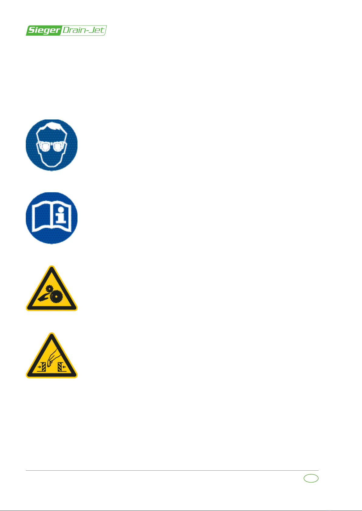
Safety glasses sticker
Sticker indicating that safety glasses must be worn.
User manual sticker
Refers to a prescribed operation.
Rotating parts sticker
Warning for mechanical danger/danger of being pulled in by moving parts.
Trapping sticker
Warning for mechanical danger/danger of crushing by moving parts.

11
112202RE101_A_M
3 GENERAL DESCRIPTION
EN
3 GENERAL DESCRIPTION
Introduction
The drain cleaner consists of the following parts:
• Frame
• Cardan shaft
• Hydraulic system
• Reel
• Side arm with hose drive
• Distance indicator
• Guide arm
• Diaphragm pump
• Pressure regulator
• Filters
• Flexible hose section
• Cleaner nozzle
Frame
The frame has attachment points for transport with a forklift. The frame is designed for attachment
to your tractor's three-point linkage.
Cardan shaft
The drain cleaner is delivered complete with a cardan shaft. This may need to be shortened. The
cardan shaft is driven by the tractor PTO shaft.
Hydraulic system
The hydraulic system is connected to the tractor's double-acting valve or a single-acting valve
with pressure-free return. The machine is operated through use of the 4-way valve block. The
wind-out and wind-up speed is controlled by the speed control valve next to the valve block.
Reel
Due to its large diameter the reel can wind up a ushing hose with a maximum length of
500metres. The drain cleaner is equipped standard with a ushing hose of this length.
Side arm with hose drive
The side arm is operated with hydraulic cylinders to position the guide arm in front of the drain
pipe. The hose drive consists of four driven rubber rollers.
Distance indicator
The distance indicator is located behind the drive rollers. The indicator measures the rolled out
hose length and can indicate the location of the blockage.
Guide arm
For road transport the guide arm must be folded in and secured, in accordance with the
instructions in this manual.

12 112202RE101_A_M
3 GENERAL DESCRIPTION
EN
Diaphragm pump
The water pump is a suction diaphragm pump, driven by the tractor PTO. The recommended
pump speed is 350 to 370 rpm. The maximum allowable speed of the pump is 540 rpm.
Pressure regulator
You can adjust the water pressure with the pressure regulator. A handle on the pressure regulator
enables you to depressurize the pump, which may be desirable, for example, when positioning
the guide arm in line with the drain pipe. The optimum operating pressure is 30 - 35 bar.
Pump pressure (bar) Cleaner nozzle pressure
(bar)
L/min at 500 metres
20 3.8 45
25 6.1 50
30 6.7 55.5
35 9.9 58.3
40 11 65
50 12.8 68.7
The return hose for the pressure regulator is connected to the top of the guide arm. The water
‘lubricates’and cleans the ushing hose.
Filters
The suction hose is tted with a suction strainer. The suction strainer is located upstream of the
diaphragm pump.
Flexible hose section
The exible hose section between the ushing hose and cleaner nozzle ensures that the cleaner
nozzle remains in the middle of the drain pipe.
Cleaner nozzle
The standard cleaner nozzle has 13 holes: 1 forward-pointing hose and 12 backward-pointing
holes at a 15° angle.
• Before the arm can be retracted, it is necessary to ensure that the
ushing hose is not located in the folding part of the arm.
• Position the drain-shaft arch before the machine is folded in
(otherwise the drain-shaft arch will contact the reel).
ATTENTION

13
112202RE101_A_M
4 COMMISSIONING
EN
4 COMMISSIONING
Introduction
• Check the drain cleaner for possible transport damage at the time of delivery. Report transport
damage to the carrier or Sieger immediately.
Cardan shaft
It may be necessary to shorten the cardan shaft (the inner and outer telescoping shaft sections
and both protective sleeves). See the instructions in the manual supplied with the cardan shaft.
Commissioning after winter storage
• Diaphragm pump: drain the antifreeze (if applicable). Dispose of the antifreeze in accordance
with national regulations.
Do not allow the pump to run longer than two minutes without a supply
of water.
ATTENTION
14 112202RE101_A_M
5 OPERATION
EN
5 OPERATION
Introduction
The chapter provides information about operating the drain cleaner.
There is a danger of crushing and bodily injury in the machine's guide
arm zone. Never stand under the guide arm when it is raised.
Safety
• Never leave the tractor engine running in an enclosed area (not
even if the doors and windows are open) due to the risk of carbon
monoxide poisoning!
• The guide arm must never be used as a hoist.
• Always wear eye protection (safety glasses). Due to the high
pressure, small, hard objects can be ejected at high speed.
• Make the machine roadworthy prior to transport on public roads.
• Check the lighting. Have an assistant help you check the brake lights.
• Adjust the tractor mirrors if necessary.

15
112202RE101_A_M
5 OPERATION
EN
Connecting to the tractor
1. Ensure that the work area is adequately
lighted.
2. Hitch the drain cleaner to the tractor.
3. Disengage the PTO shaft and shut down
the engine on the tractor, and take the
ignition key with you.
4. Fit the cardan shaft (adapted to length if
necessary) to the tractor PTO shaft.
5. Secure the tractor end of the protective
sleeve to the tractor with the attachment
chain to prevent it from rotating with the
shaft.
6. Ensure that the protective sleeve on the
drain cleaner side is secured against
rotation with the other attachment chain.
7. Attach the hydraulic hoses; the connection
for the pump side is marked in red.
8. Connect the 7-pole connector for the brake
lights and direction indicators to the tractor
socket.
9. WR model: connect the plug for the
electrical circuit (black - / white +).
The maximum permissible speed of the tractor PTO shaft is 540 rpm.
Do not exceed this speed.
Do not use the chains to hang up the cardan shaft.
Do not stand on the cardan shaft.
The cardan shaft can become very hot during use. Do not touch the
cardan shaft during or soon after use.
• Rotating parts (cardan shaft).
• Only use the cardan shaft with the protective sleeve and protective
guards in place and in good condition.
• Maintain a safe distance from the rotating cardan shaft.
• Prior to maintenance on the cardan shaft:
• Disengage the PTO shaft and shut down the engine on the tractor.
• Remove the ignition key from the ignition lock cylinder.
ATTENTION
ATTENTION
16 112202RE101_A_M
5 OPERATION
EN
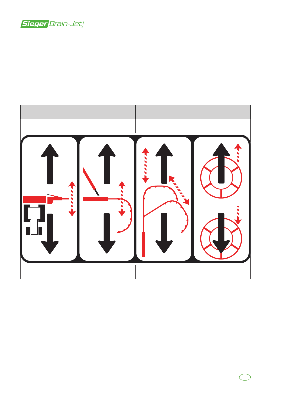
Lever 4
(HS/WR model)
Lever 3 Lever 2 Lever 1
Swing backwards Raise arm Extend arm
Fold arm out
Reel out
Swing forwards Lower arm Retract arm
Fold arm in
Reel in
Hydraulic system operation
The machine is operated through use of the 4-way valve block. The wind-out and wind-up speed
is controlled with the speed control valve next to the valve block.
The sticker on the control panel graphically indicates the various functions of the levers.
Note: Lever 4 is only present on the HS and WR model.
17
112202RE101_A_M
5 OPERATION
EN
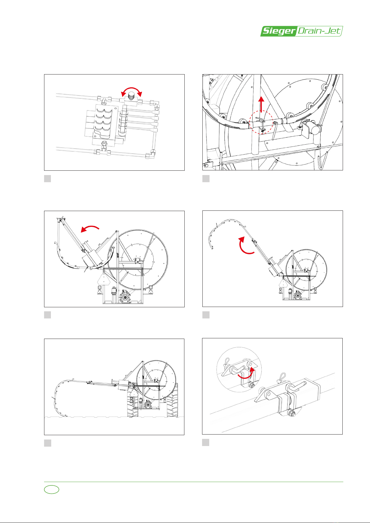
Release the arm from the road transport
retainer.
Lower the arm ±45 degrees (lever 3). Fold out the arm as far as possible
(lever2).
Pressurize the hydraulic system.
The speed can be adjusted with the speed
control valve.
1
3
2
4
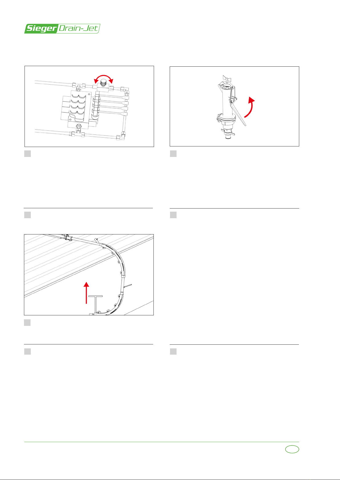
Machine operation: winding out (feeding in)
Lower the arm to the ground (lever 3). From transport position to operating
position
If necessary, retract cylinder ±1 cm with
lever 2.
6
5

18 112202RE101_A_M
5 OPERATION
EN
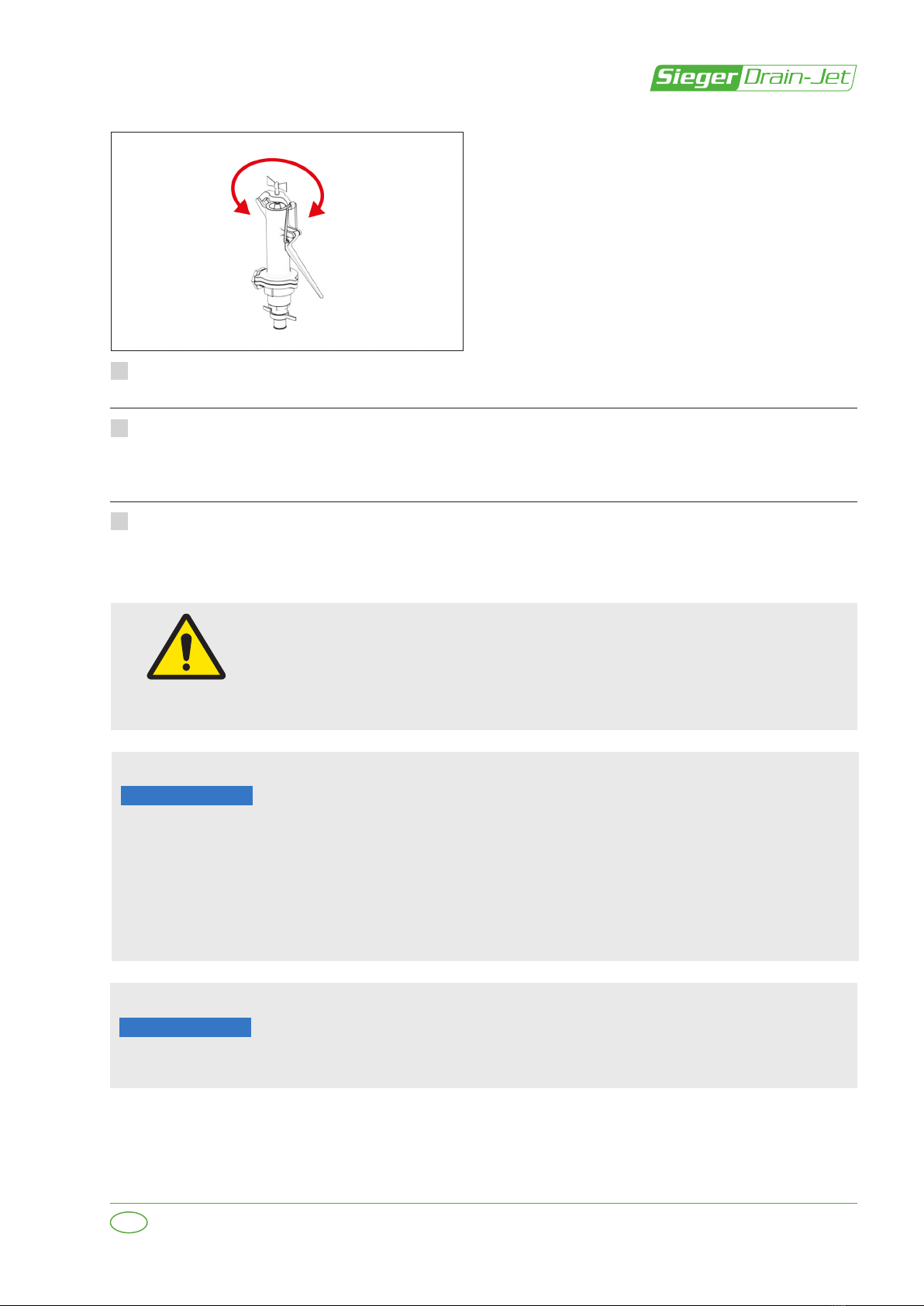
Drive the tractor to the ditch or pit.
Position the drain-shaft arch in front of the
drain.
Secure the drain-shaft arch with the
ground anchor.
Lay/place the suction hose in the pit or
water tank. Connect the return hose for
the pressure regulator to the top of the
guide arm. The water ‘lubricates’and
cleans the ushing hose.
Disengage the pressure regulator. Engage
the PTO.
Recommended speed for the pump is 350 – 370 rpm. Use the lowest possible speed necessary
to achieve the operating pressure of 30-35 bar.
Run the reel slowly to roll out the hose;
tighten the tension roller until the drive no
longer slips.
Reel out the hose carefully until the nozzle
is ±3 centimetres from the drain (lever 1).
Set the distance indicator to 0.
7
9
11
8
10
12
19
112202RE101_A_M
5 OPERATION
EN
Engage the pressure regulator and adjust it to 35 bar.
Reel out the hose at ±30 metres per minute. Retract the hose ±15 metres if the hose gets
stuck or the drive wheels slip. Then continue reeling out, assuming that the end has not yet
been reached.
If the cleaner nozzle gets stuck approximately 50 metres into the drain pipe due to heavy
deposits: retract the hose completely to ush the contamination out of the drain pipe. Repeat
to clean the next section of drain pipe.
13
14
15
• Prevent the polyethylene hose from kinking by positioning the drain-
shaft arch no more than 5 to 10 centimetres from the drain.
• Raise the drain cleaner until the angle of the PTO shaft is
approximately 10 degrees (maximum 12 degrees).
• Stop immediately when a blockage is reached.
• Stop immediately at the end of the drain pipe.
• Never allow the ushing hose to stand still in the drain pipe for more
than ten minutes.
• Retract the hose at a lower speed.
Ensure that no one is within the working zone around the machine when
the machine is in operation.
• Only remove the locking pin from the pivot point if the arm is resting
on the ground.
• Do not place your hands between the drive wheels.
When the cleaner nozzle is in the drain:
• Do not switch o the pump!
• Keep the hose under pressure!
• Never leave the machine unattended!
ATTENTION
ATTENTION
20 112202RE101_A_M
5 OPERATION
EN
Roll up the hose once the end of the
drain is reached. Reduce the speed from
20 to 25 metres per minute by adjusting
the throttling valve. Watch the distance
indicator carefully. Stop the reel once the
hose is out of the drain.
Disengage the pressure regulator.
Disengage the PTO shaft.
Raise arm slightly and drive to the next
drain.
Remove suction hose from the water.
Remove suction hose from the water.
Remove ground anchor.
Machine operation: winding up
1 2
3 4
5
67
This manual suits for next models
2
Table of contents


