Siel SAFEPOWER S series User manual

IV420E Rev.00 SIEL S.p.A. Installation and user manual
Date of issue: 2019-01-29 Pag. 0 di 52 + FR
50-200kVA PF=1 UPS
INSTALLATION AND USER MANUAL
SAFEPOWER S
KEEP FOR FUTURE REFERENCE
for the entire life of the appliance


IV420E Rev.00 SIEL S.p.A. Installation and user manual
Date of issue: 2019-01-29 Pag. 1 di 72+ FR
All rights reserved.
The information in this document is subject to change without notice.
Publish statement
Thank you for purchasing this series UPS.
This series UPS is an intelligent, three phase in Three phase out, high frequency online
UPS designed by our R&D team who is with years of designing experiences on UPS.
With excellent electrical performance, perfect intelligent monitoring and network
functions, smart appearance, complying with EMC and safety standards, The UPS
meets the world’s advanced level.
Read this manual carefully before installation
This manual provides technical support to the operator of the equipment.

IV420E Rev.00 SIEL S.p.A. Installation and user manual
Date of issue: 2019-01-29 Pag. 2 di 72+ FR
Contents
1.Safety............................................................................................................................................................3
1.1 Safety notes .......................................................................................................................................3
1.2 Symbols used in this guide............................................................................................................4
2.Main Features.............................................................................................................................................4
2.1 Summarization...................................................................................................................................4
2.2 Functions and Features..................................................................................................................4
3.Installation...................................................................................................................................................5
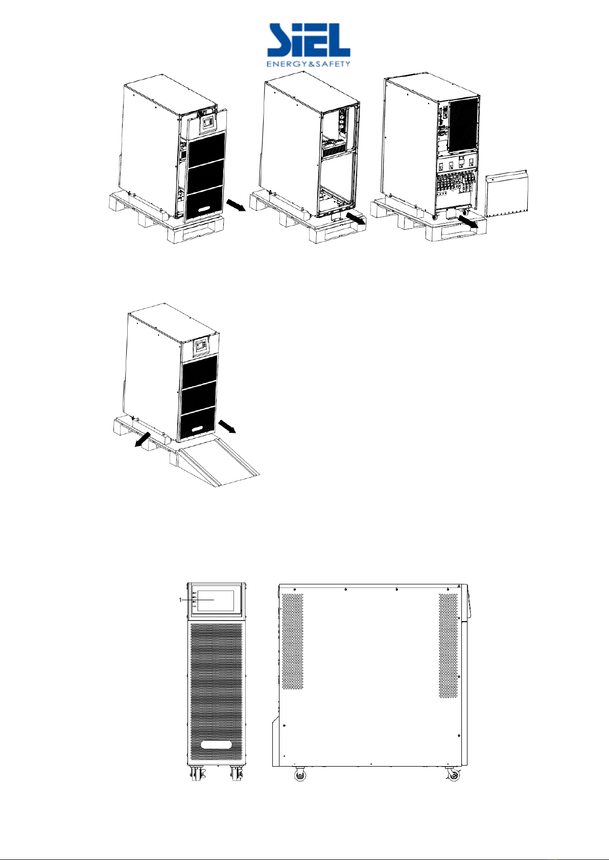
3.1 Unpacking and checking ................................................................................................................5
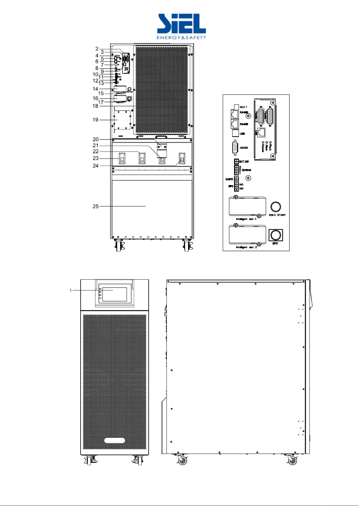
3.2 Cabinet Outlook ................................................................................................................................ 6
3.3 LCD control panel........................................................................................................................... 11
3.4 Installation notes............................................................................................................................. 11
3.5 External Protective Devices..........................................................................................................12
3.6 Power Cables...................................................................................................................................12
3.7 Power cable connect......................................................................................................................15
3.8 Battery connection.........................................................................................................................19
3.9 UPS parallel Installation.................................................................................................................20
3.10 LBS installation.............................................................................................................................21
3.11 Computer access..........................................................................................................................22
4.Operation...................................................................................................................................................24
4.1 Operation Modes.............................................................................................................................24
4.2 Turn on/off UPS...............................................................................................................................26
4.3 The LCD Display..............................................................................................................................31
4.3 The Display.......................................................................................................................................31
4.4 Display Messages/Troubleshooting...........................................................................................58
4.5 Options..............................................................................................................................................60
Relay card:..............................................................................................................................................61
Appendix 1 Specifications..........................................................................................................................62
Appendix 2 Problems and Solution..........................................................................................................64
Appendix 3 USB communication port definition .................................................................................. 65
Appendix 4 RS232 communication port definition...............................................................................66
Appendix 5 RS485 communication port definition...............................................................................67
Appendix 6 Optional port definition......................................................................................................... 68
Appendix 7 REPO instruction....................................................................................................................69
Appendix 8 Backfeed Protection...............................................................................................................70

IV420E Rev.00 SIEL S.p.A. Installation and user manual
Date of issue: 2019-01-29 Pag. 3 di 72+ FR
1.Safety
Important safety instructions - Save these instructions
There exists dangerous voltage and high temperature inside the UPS. During the
installation, operation and maintenance, please abide the local safety instructions and relative
laws, otherwise it will result in personnel injury or equipment damage. Safety instructions in this
manual act as a supplementary for the local safety instructions. Our company will not assume
the liability that caused by disobeying safety instructions.
1.1 Safety notes
1. Even no connection with utility power, 220/230/240VAC voltage may still exist at UPS
terminal!
2. For the sake of human being safety, please well earth the UPS before starting it.
3.Don’t open or damage battery, for the liquid spilled from the battery is strongly poisonous and
do harmful to body!
4.Please avoid short circuit between anode and cathode of battery, otherwise, it will cause
spark or fire!
5.Don’t disassemble the UPS cover, or there may be an electric shock!
6.Check if there exists high voltage before touching the battery
7.Working environment and storage way will affect the lifetime and reliability of the UPS. Avoid
the UPS from working under following environment for long time
◆Area where the humidity and temperature is out of the specified range(temperature 0
to 40℃, relative humidity 5%-95%)
◆Direct sunlight or location nearby heat
◆Vibration Area with possibility to get the UPS crashed.
◆Area with erosive gas, flammable gas, excessive dust, etc
8.Keep ventilations in good conditions otherwise the components inside the UPS will be
over-heated which may affect the life of the UPS.

IV420E Rev.00 SIEL S.p.A. Installation and user manual
Date of issue: 2019-01-29 Pag. 4 di 72+ FR
1.2 Symbols used in this guide
WARNING!
Risk of electric shock
CAUTION!
Read this information to avoid equipment damage
2.Main Features
2.1 Summarization
This series UPS is a kind of three-in-three-out high frequency online UPS.
The UPS can solve most of the power supply problems, such as blackout, over-voltage,
under-voltage, voltage sudden drop, oscillating of decreasing extent, high voltage pulse, voltage
fluctuation, surge, inrush current, harmonic distortion (THD), noise interference, frequency
fluctuation, etc..
This UPS can be applied to different applications from computer device, automatic equipment,
communication system to industry equipment.
2.2 Functions and Features
◆Integrated solution for data center
UPS can be integrated with battery cabinet, PDU external maintenance bypass, offering
excellent choice for data center.
◆3Phase In/3Phase Out UPS
It is 3Phase In/3Phase Out high-density UPS system, of which input current is kept in balance.
No unbalance problem might occur.
◆Digital Control
This series UPS is controlled by Digital Signal Processor (DSP); enhance, it increases
reliability, performance, self-protection, and self-diagnostics and so on.
◆Battery Configurable
From 30 blocks to 50 blocks, the battery voltage of this series UPS can be configured at 30
blocks, 32 blocks, 34 blocks, 36 blocks, 38 blocks, 40 blocks, 42 blocks, 44 blocks, 46 blocks, 48
blocks or 50 blocks according to your convenience.
◆Charging Current is configurable
Via setting tool, the user may set the capacity of the batteries as well as reasonable charging
current as well as maximum charging current. Constant voltage mode, constant current mode or
floating mode can be switched automatically and smoothly.
◆Intelligent Charging Method
The series UPS adopts advanced three-stage charging method—
1st stage: high current constant current charging
to guarantee to charge back to 90%;
2nd-stage: Constant Voltage
In order to vitalize battery and make sure batteries are fully charged
3rd stage: floating mode.
With this 3-stage charging method, it extends the life of the batteries and guarantees fast charging.
◆LCD Display

IV420E Rev.00 SIEL S.p.A. Installation and user manual
Date of issue: 2019-01-29 Pag. 5 di 72+ FR
With LCD plus LED displays, the user may easily get UPS status and its operational
parameters, such as input/output voltage, frequency & load%, battery % and ambient
temperature, etc...
◆Intelligent Monitoring Function
Via optional SNMP Card, you may remotely control and monitor the UPS.
◆EPO Function
The series UPS may be completely shut off when the EPO is pressed. REPO function
(Remote EPO) is also available in this series UPS.
3.Installation
3.1 Unpacking and checking
Don’t lean the UPS when moving it out from the packaging
Procedure
Step 1 Use a pallet truck to transport the UPS to the installation position.
Step 2 Check the UPS packing.
Step 3 Hold the sliding plate steady. Cut and remove the binding tapes.
Step 5 Remove the plastic bag and take out the fittings box.
Step 6 Check that the UPS is intact.
1. Visually inspect the UPS appearance for shipping damage. If it is damaged, notify the
carrier immediately.
2. Check the accessories according to the packing list and contact the dealer in case of missing
parts.
Step 7 Remove the front panel and real panel to remove the L-shaped bracket that secures the
cabinet and the pallet, and secure the sliding

IV420E Rev.00 SIEL S.p.A. Installation and user manual
Date of issue: 2019-01-29 Pag. 6 di 72+ FR
Step 8 Remove the front panel and real panel to remove the L-shaped bracket and the plates at
the left and right side of the UPS that secures the cabinet and the pallet, and secure the sliding
3.2 Cabinet Outlook
50kVA &60kVA
Front View Side View

IV420E Rev.00 SIEL S.p.A. Installation and user manual
Date of issue: 2019-01-29 Pag. 7 di 72+ FR
Rear View
100kVA &120kVA
Front View Side View

IV420E Rev.00 SIEL S.p.A. Installation and user manual
Date of issue: 2019-01-29 Pag. 8 di 72+ FR
Rear View
160kVA
Front View Side View

IV420E Rev.00 SIEL S.p.A. Installation and user manual
Date of issue: 2019-01-29 Pag. 9 di 72+ FR
Rear View
200kVA
Front View Side View

IV420E Rev.00 SIEL S.p.A. Installation and user manual
Date of issue: 2019-01-29 Pag. 10 di 72+ FR
Rear View Front View
(1) LCD panel
(2) Parallel port 1
(3) Parallel port 2
(4) Temperature sensor port (for NTC)
(5) RS485 port (for RS485 temperature sensor)
(6) RS485 port (for RS485 temperature sensor)
(7) USB port
(8) RS232
(9) LBS port
(10) BAT_SW : detect battery switch status
(11) Optional port (Port for feedback
protection, or for battery breaker driver to
prevent battery over-drain after UPS shuts down)
(12) MAINTAIN-AUXSWS port
(13) REPO port
(14) Intelligent Slot 1 (SNMP card/ Relay card)
(15) Cold-start
(16) Intelligent Slot 2 (SNMP card/ Relay card)
(17) EPO button
(18) Cover for UPS Maintenance
(19) SPD (optional) for 100-120kVA;
Front door for 200kVA(Battery and neutral
copper bar and maintenance switch)
(20) Maintenance breaker (200kVA is switch)
cover
(21) Maintenance breaker (200kVA is switch)
(22) Bypass breaker
(23) Mains breaker
(24) Output breaker
(25) Terminal block cover

IV420E Rev.00 SIEL S.p.A. Installation and user manual
Date of issue: 2019-01-29 Pag. 11 di 72+ FR
3.3 LCD control panel
LCD control panel introduction
(1) LED(from top to bottom: “Fault”, “bypass”, “battery”, “inverter”)
(2) LCD display
3.4 Installation notes
Note: Consider for the convenience of operation and maintenance, the space in
front and back of the cabinet should be left at least 100cm and 80cm respectively when
installing the cabinet.
◆Please place the UPS in a clean, stable environment, avoid the vibration, dust, humidity,
flammable gas and liquid, corrosive. To avoid from high room temperature, a system of room
extractor fans is recommended to be installed. Optional air filters are available if the UPS operates
in a dusty environment.
◆The environment temperature around UPS should keep in a range of 0℃~40℃. If the
environment temperature exceeds 40℃, the rated load capacity should be reduced by 12%per
5℃. The max temperature can't be higher than 50℃.
◆If the UPS is dismantled under low temperature, it might be in a condensing condition. The
UPS can't be installed unless the internal and external of the equipment is fully dry. Otherwise,
there will be in danger of electric shock.
◆Batteries should be mounted in an environment where the temperature is within the required
specs. Temperature is a major factor in determining battery life and capacity. In a normal
installation, the battery temperature is maintained between 15°C and 25°C. Keep batteries away
from heat sources or main air ventilation area, etc.
WARNING!
Typical battery performance data are quoted for an operating
temperature between 20°C and 25°C. Operating it above this range will
reduce the battery life while operation below this range will reduce the
battery capacity.
◆Should the equipment not be installed immediately it must be stored in a room so as to
protect it against excessive humidity and or heat sources.
CAUTION!
An unused battery must be recharged every 6months Temporarily
connecting the UPS to a suitable AC supply mains and activating it for
the time required for recharging the batteries.
◆The highest altitude that UPS may work normally with full load is 1500 meters. The load
capacity should be reduced when this UPS is installed in place whose altitude is higher than 1500
meters, shown as the following table:

IV420E Rev.00 SIEL S.p.A. Installation and user manual
Date of issue: 2019-01-29 Pag. 12 di 72+ FR
(Load coefficient equals max load in high altitude place divided by nominal power of the UPS)
Altitude
(m)
1500
2000
2500
3000
3500
4000
4500
5000
Load
coefficient
100%
95%
90%
85%
80%
75%
70%
65%
◆The UPS cooling is depending on fan, so it should be kept in good air ventilation area.
There are many ventilation holes on the front and rear, so they should not be blocked by any exotic
obstacles.
3.5 External Protective Devices
For safety reasons, it is necessary to install, external circuit breaker at the input A.C. supply and
the battery. This chapter provides guidelines for qualified installers that must have the knowledge of
local wiring practices for the equipment to be installed.
◆External Battery
The UPS and its associated batteries are protected against the effect of over-current
through a DC compatible thermo-magnetic circuit-breaker (or a set of fuses) located close to
the battery.
◆UPS Output
Any external distribution board used for load distribution shall be fitted with protective
devices that may avoid the risk of UPS overloaded.
◆Over-current
Protection device shall be installed at the distribution panel of the incoming main supply. It
may identify the power cables current capacity as well as the overload capacity of the system.
CAUTION!
Select a thermo magnetic circuit-breaker with an IEC 60947-2 trip
curve C (normal) for 125% of the current as listed below.
3.6 Power Cables
◆The cable design shall comply with the voltages and currents provided in this section, Kindly
follow local wiring practices and take into consideration the environmental conditions (temperature
and physical support media) .
WARNING!
Upon starting. Please ensure that you are aware of the location and
operation of the external isolators which are connected to the UPS
input/bypass supply of the mains distribution panel. Check to see if
these supplies are electrically isolated. And post and necessary
warning signs to prevent any inadvertent operation.
3.6.1 Recommended cross-sectional areas for power cables
UPS
cabinet
Cable Dimension
AC Input
(mm2)
AC Output
(mm2)
DC Input
(mm2)
Grounding
(mm2)
50kVA
25
16
50
16
60kVA
35
25
50
25
100kVA
70
50
120
35
120kVA
95
70
150
50
160kVA
120
95
185
70
200kVA
150
100
120*2
95

IV420E Rev.00 SIEL S.p.A. Installation and user manual
Date of issue: 2019-01-29 Pag. 13 di 72+ FR
◆When selecting, connecting, and routing power cables, follow local safety regulations and
rules.
◆If external conditions such as cable layout or ambient temperatures change, perform
verification in accordance with the IEC-60364-5-52 or local regulations.
◆If the rated voltage is 400 V, multiply the currents by 0.95. If the rated voltage is 415 V,
multiply the currents by 0.92.
◆If primary loads are non-linear loads, increase the cross-sectional areas of neutral
wires1.5–1.7 times.
◆The nominal battery discharge current refers to the current of forty 12 V batteries at 480V
in standard configuration.
◆The maximum battery discharge current refers to the current when forty 12 V batteries in
standard configuration, that is, two hundred and forty 2 V battery cells (1.67 V/cell), stop
discharging.
◆The battery cable specifications are selected based on 40 batteries by default and
compatible with application scenarios with 30–50 batteries.
◆When the mains input and bypass input share a power source, configure both types of input
power cables as mains input power cables. The cables listed in Table are used only when
the following requirements are met:
−Routing mode: Routing the cables over the cable ladder or bracket in a single layer
(IEC60364-5-52 middle E).
−The ambient temperature is 30°C.
−The AC voltage loss is less than 3%, and the DC voltage loss is less than 1%.
−90°C copper flexible cable.
−The length of the AC power cables of a UPS is no longer than 30 m and DC power cables
no longer than 50 m.
3.6.2 Power cable connector requirements
Model
Connector
Connection
Mode
Bolt Type
Bolt Hole
Diameter
Torque
50-60kVA
Mains input
connector
Crimped OT
terminals
M8
M8
20N•m
Bypass input
connector
Crimped OT
terminals
M8
M8
20N•m
Battery input
connector
Crimped OT
terminals
M8
M8
20N•m
Output
connector
Crimped OT
terminals
M8
M8
20N•m
Grounding
connector
Crimped OT
terminals
M8
M8
20N•m
100-120kVA
Mains input
connector
Crimped OT
terminals
M10
11mm
26N•m
Bypass input
connector
Crimped OT
terminals
M10
11mm
26N•m
Battery input
connector
Crimped OT
terminals
M10
11mm
26N•m
Output
connector
Crimped OT
terminals
M10
11mm
26N•m
Grounding
connector
Crimped OT
terminals
M10
11mm
26N•m

IV420E Rev.00 SIEL S.p.A. Installation and user manual
Date of issue: 2019-01-29 Pag. 14 di 72+ FR
160kVA
Mains input
connector
Crimped OT
terminals
M10
11mm
26N•m
Bypass input
connector
Crimped OT
terminals
M10
11mm
26N•m
Battery input
connector
Crimped OT
terminals
M10
11mm
26N•m
Output
connector
Crimped OT
terminals
M10
11mm
26N•m
Grounding
connector
Crimped OT
terminals
M10
11mm
26N•m
200kVA
Mains input
connector
Crimped OT
terminals
M10
11mm
26N•m
Bypass input
connector
Crimped OT
terminals
M10
11mm
26N•m
Battery input
connector
Crimped OT
terminals
M10
11mm
26N•m
Output
connector
Crimped OT
terminals
M10
11mm
26N•m
Grounding
connector
Crimped OT
terminals
M10
11mm
26N•m
3.6.3 Recommended input front-end and output back-end circuit breakers
UPS capacity
Component
Specifications
50kVA
Mains input circuit breaker
100A 3P
Bypass input circuit breaker
100A 3P
Output branch circuit breaker
100A 3P
60kVA
Mains input circuit breaker
125A 3P
Bypass input circuit breaker
125A 3P
Output branch circuit breaker
125A 3P
100kVA
Mains input circuit breaker
200A 3P
Bypass input circuit breaker
200A 3P
Output branch circuit breaker
200A 3P
120kVA
Mains input circuit breaker
250A 3P
Bypass input circuit breaker
250A 3P
Output branch circuit breaker
250A 3P
160kVA
Mains input circuit breaker
320A 3P
Bypass input circuit breaker
320A 3P
Output branch circuit breaker
320A 3P
200kVA
Mains input circuit breaker
400A 3P
Bypass input circuit breaker
400A 3P
Output branch circuit breaker
400A 3P

IV420E Rev.00 SIEL S.p.A. Installation and user manual
Date of issue: 2019-01-29 Pag. 15 di 72+ FR
CAUTION!
Protective earth cable: Connect each cabinet to the main ground
system. For Grounding connection, follow the shortest route
possible.
WARNING!
Failure to follow adequate earthing procedures may result in
electromagnetic interference or in hazards involving electric shock
and fire
3.7 Power cable connect
Once the equipment has been finally positioned and secured, connect the power cables as
described in the following procedure.
Verify the UPS is totally isolated from its external power source and also all power isolators of the
UPS are open. Check to see if they are electrically isolated, and post any necessary warning signs to
prevent their inadvertent operation.
Open the UPS rear panel; Remove the cover of terminals for wiring easily.
3.7.1 Common input connection
50kVA&60kVA

IV420E Rev.00 SIEL S.p.A. Installation and user manual
Date of issue: 2019-01-29 Pag. 16 di 72+ FR
100kVA-160 kVA
200 kVA
INPUT Primary input Line
OUTPUT
Vout-L1: Output Phase L1
Vin-L1: Primary input Phase L1
Vout -L2: Output Phase L2
Vin-L2: Primary input Phase L2
Vout -L3: Output Phase L3
Vin-L3: Primary input Phase L3
Vout -N: Output Neutral
Vin-N: Input Neutral for primary and
secondary input
PE: Grounding
BAT+: Positive terminal of the batteries string
BATN: Neutral terminal of the batteries string
BAT-: Negative terminal of the batteries string

IV420E Rev.00 SIEL S.p.A. Installation and user manual
Date of issue: 2019-01-29 Pag. 17 di 72+ FR
3.7.2 Dual input connection
50kVA &60kVA
100kVA -160kVA
200kVA

IV420E Rev.00 SIEL S.p.A. Installation and user manual
Date of issue: 2019-01-29 Pag. 18 di 72+ FR
Mains Primary input Line
Output
Bypass Secondary/Bypass input line
(optional)
Vout-L1: Output Phase L1
Vin-L1: Primary input Phase L1
Vout-L2: Output Phase L2
Vin-L2: Primary input Phase L2
Vout-L3: Output Phase L3
Vin-L3: Primary input Phase L3
Vout-N: Output Neutral
Vin-N: Input Neutral for primary and
secondary input
PE: Grounding
BPS-L1: Secondary input Phase L1
BAT+: Positive terminal of the batteries string
BPS-L2: Secondary input Phase L2
BATN: Neutral terminal of the batteries string
BPS-L3: Secondary input Phase L3
BAT-: Negative terminal of the batteries string
Warning!
In the case of “Dual input” operation, make sure the copper wire
between each input lines have been removed. The AC input and the AC
bypass supplies must be referenced to the same neutral point.
Choose appropriate power cable. (Refer to the table above) and pay attention to the
diameter of the connection terminal of the cable that should be greater than or equal to that of
the connection poles;
WARNING!
If the load equipment is not ready to accept power on the
arrival of the commissioning engineer then ensure that the system
output cables are safely isolated at their ends
Connect the safety earth and any necessary bonding earth
cables to the copper earth screw located on the floor of the
equipment below the power connections. All cabinets in the UPS
must be grounded properly.
CAUTION!
The earthing and neutral bonding arrangement must be in
accordance with local and national codes of practice.
Other manuals for SAFEPOWER S series
1
This manual suits for next models
1
Table of contents
Other Siel UPS manuals

Siel
Siel Green Point User manual

Siel
Siel SAFEPOWER SPM User manual

Siel
Siel SAFEPOWER S User manual

Siel
Siel SAFEPOWER S series User manual

Siel
Siel SAFEPOWER-EVO-HF Series User manual

Siel
Siel Green Point 6 20KVA User manual

Siel
Siel 6kVA User manual

Siel
Siel SAFEPOWER EVO HFT Guide

Siel
Siel SAFEPOWER S User manual

Siel
Siel SAFEPOWER EVO-HF 200 Guide