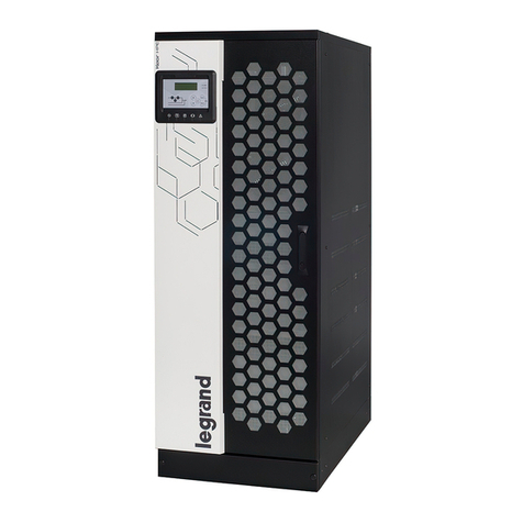
Siel Safepower Evo 20 User manual

l�
un I Jet
,
SIEL SAFEPOWER Evo - руководство по эксплуатации. Юниджет
Постоянная ссылка на страницу: https://www.uni-jet.com/catalog/ibp/on-line-
ibp/siel-safepower-evo/

IV306E Rev. 004 Siel S.p.A. Page 1 of 37 + 12 Tables, 14 Figures + FR
Issued date: 2014-03-24
Please read this manual before the installation and the start-up
of equipment!
KEEP FOR FUTURE REFERENCE
For the entire life of the appliance
This manual should be considered an integral part of the UPS unit
INSTRUCTION MANUAL FOR
SAFEPOWER-EVO SERIES

IV306E Rev. 004 Siel S.p.A. Page 2 of 37 + 12 Tables, 14 Figures + FR
Issued date: 2014-03-24
CONTENTS
IMPORTANT WARNINGS..................................................................................................................................4
INTRODUCTION ................................................................................................................................................10
TAPPLICABLE REGULATIONS .....................................................................................................................10
DESCRIPTION OF SYSTEM ............................................................................................................................11
BLOCK DIAGRAM (FIGURE 1). .............................................................................................................................11
INTERACTIVE MODE OF OPERATION...................................................................................................................14
DESCRIPTION OF PARALLEL OPERATION ...........................................................................................................14
DETAILED ANALYSIS OF PARALLEL OPERATION................................................................................................15
1- POWER PARALLEL............................................................................................................................................15
2- REDUNDANCY PARALLEL ................................................................................................................................15
EQUIPMENT ..........................................................................................................................................................16
CONTROL,MEASUREMENT AND SIGNALLING PANEL.........................................................................................16
FUNCTIONAL DIAGRAM........................................................................................................................................19
DESCRIPTION OF THE BACK-FEED PROTECTION SENSOR ..................................................................................19
REMOTE SIGNALLING SYSTEMS. .........................................................................................................................20
DETAILED DESCRIPTION OF THE SIGNALS AVAILABLE ON THE CN1 CONNECTOR AND ON THE TERMINAL
BOARDS. ................................................................................................................................................................20
DESCRIPTION OF COMMUNICATION FIBRE OPTICS ............................................................................................21
DETAILED DESCRIPTION OF FIBRE OPTICS CONNECTIONS................................................................................21
INSTALLATION .................................................................................................................................................22
CHOOSING THE INSTALLATION LOCATION ........................................................................................................22
VISUAL INSPECTION .............................................................................................................................................22
ENVIRONMENTAL CONSIDERATIONS ..................................................................................................................22
HANDLING ............................................................................................................................................................22
SAFETY CONSIDERATIONS...................................................................................................................................23
BATTERIES............................................................................................................................................................23
ELECTRICAL CONNECTIONS.......................................................................................................................24
POWER CONNECTIONS .........................................................................................................................................24
SIGNAL CONNECTIONS .........................................................................................................................................24
MAINTENANCE .................................................................................................................................................26
OPERATING INSTRUCTIONS.........................................................................................................................26
USING THE CONTROL PANEL PUSHBUTTONS ......................................................................................................26
START-UP AND SUBSEQUENT ACTIONS................................................................................................................29
EMERGENCY DEVICE (EPO) OPERATION ...........................................................................................................32
FUSES...................................................................................................................................................................32
OPTIONS ..............................................................................................................................................................32
OPTION 1: FILTRI RFI .........................................................................................................................................33
OPTION 2: INPUT POWER FACTOR CORRECTION...............................................................................................33
OPTION 3: REDUCTION OF DISTORTION OF INPUT POWER FOR SIX-PHASE UPS .............................................33

IV306E Rev. 004 Siel S.p.A. Page 3 of 37 + 12 Tables, 14 Figures + FR
Issued date: 2014-03-24
OPTION 4: REDUCTION OF INPUT CURRENT DISTORTION FOR 12-PULSE UPSS...............................................33
OPTION 5: RESERVE MAINS ISOLATION TRANSFORMER ...................................................................................33
OPTION 6: RECTIFIER INPUT ISOLATION TRANSFORMER .................................................................................33
OPTION 7: RECTIFIER AND RESERVE INPUT ISOLATION TRANSFORMER .........................................................33
OPTION 8: REMOTE SWITCH FOR DISCONNECTING THE RESERVE MAINS IN CASE OF A MAINS POWER BREAK
AND UPS OUTPUT ISOLATION SENSOR ................................................................................................................33
OPTION 9: BACK-FEED TO MAINS PROTECTION WITH SWITCH IN THE UPS ..................................................33
OPTION 10: BACK-FEED PROTECTION WITH REMOTE SWITCH .......................................................................34
OPTION 11: UPS OUTPUT ISOLATION SENSOR FOR REGULAR OPERATION IN IT.............................................34
OPTION 12: RESTRICTION OF THE INPUT CURRENT AND INHIBITION OF FAST LOADING FOR OPERATION
WITH GENERATOR,SEQUENTIAL START OF RECTIFIERS...................................................................................34
OPTION 13: BATTERY TEMPERATURE READING KIT. ........................................................................................34
OPTION 14: BATTERY CABINET TEMPERATURE READING KIT,BY MEANS OF OPTIC FIBRES..........................34
OPTION 15: CUSTOMER INTERFACE BOARD WITH RS232 SERIAL PORT..........................................................34
OPTION 16: REMOTE MIMIC PANEL ....................................................................................................................34
OPTION 17: OCSYSTEM CONTROL SYSTEM .......................................................................................................35
OPTION 18: SMS (SIEL MONITORING SOFTWARE) CONTROL SYSTEM...........................................................35
OPTION 19: CONNECTION TO SNMP NETWORK................................................................................................35
OPTION 20: TELEGLOBALSERVICE .....................................................................................................................35
OPTION 21: POWER ADAPTER AUTOTRANSFORMERS........................................................................................36
OPTION 22: UPS USED AS FREQUENCY CONVERTER .........................................................................................36
OPTION 23: SECOND CLIENT INTERFACE BOARD...............................................................................................36
OPTION 24: SECOND RS232 INTERFACE.............................................................................................................36
OPTION 25: SINGLE BATTERY FOR PARALLEL OPERATION ..............................................................................36
OPTION 26: INCORPORATED BATTERIES ............................................................................................................36
OPTION 27: 24-PULSE RECTIFIER BRIDGE ..........................................................................................................36
OPTION 28: REMOTE SENSING CIRCUIT..............................................................................................................36
OPTION 29: VERSIONS WITHOUT DISCONNECTING SWITCHES .........................................................................37
TECHNICAL SPECIFICATIONS.....................................................................................................................37
MAX POWER OF INPUT AND OUTPUT CABLES: TABLE 1
RECTIFIER INPUT SPECIFICATIONS TABLE 2
RECTIFIER OUTPUT SPECIFICATIONS TABLE 3
INVERTER INPUT SPECIFICATIONS TABLE 4
INVERTER OUTPUT SPECIFICATIONS TABLE 5
STATIC SWITCH SPECIFICATIONS: TABLE 6
COMPLETE UPS SPECIFICATIONS: TABLE 7
MECHANICAL SPECIFICATIONS TABLE 8
OTHER DETAILS: TABLE 9
PARALLEL: TABLE 10
AVAILABLE OPTIONS: TABLE 11
EMERGENCY NETWORK FUSES: TABLE 12

IV306E Rev. 004 Siel S.p.A. Page 4 of 37 + 12 Tables, 14 Figures + FR
Issued date: 2014-03-24
IMPORTANT WARNINGS
This section contains some of the most important warnings which must be read and understood before
the installation and start-up of the equipment.
Read the following warnings very carefully.
Should you need any further information regarding this matter, please do not hesitate to contact SIEL
S.p.A.
This manual shall be considered an integral part of the UPS and be stored for the entire product life.
Keep it in an easily accessible location close to the device.
For any operation on the UPS carefully respect the instructions below.
The different paragraphs of the warnings and of the manual are signalled by the following symbols:
Danger (situation which can cause severe injuries to people and/or damages to equipment)
Risk of electrical shock (danger of death)
Important notice
Information regarding disposal
Installation instructions
Use instructions
Unpacking instructions
Introduction
These warnings are meant to point out and, as far as possible, to eliminate the main dangerous
conditions; they shall be completed with the information provided in each chapter of the manual
(specifically in the chapters “Installation” and “Electrical connections”)
Dangerous voltage
The static switch contains potentially fatal voltages.
All dangerous voltages within the UPS equipment are segregated into special areas, which are only
accessible using tools not provided with this equipment.

IV306E Rev. 004 Siel S.p.A. Page 5 of 37 + 12 Tables, 14 Figures + FR
Issued date: 2014-03-24
All maintenance or repair work which requires access to those areas can only be carried out by
authorised SIEL S.p.A. personnel.
Introduction of objects
Do not insert any objects into the air vents, avoid contact with fluids and clean away with a dry cloth.
These precautions must be observed even when the machine is switched off.
Equipment Top
The UPS top panels are not designed to withstand heavy weights. Never climb on the top of the UPS
or place service platforms or other similar objects on it and do not use them as a support for further
frameworks (cable grommets, brackets, etc...)
Batteries
These power supplies are connected to batteries which store electrical energy, often of a high capacity.
They should therefore be operated with utmost care due to the high voltage which is present even
when the loads are apparently not powered. It is important to remember that the residual voltage
contained in seemingly flat batteries may still be potentially lethal. When working on batteries, be
especially careful not to generate accidental electrical arcs.
Electrolyte
If the electrolyte leaks from the batteries, it is necessary to store them in sulphuric acid-resistant
containers and dispose of them according to applicable laws.
If the electrolyte comes into contact with skin, rinse with plenty of water.
If it comes into contact with eyes, rinse immediately with plenty of water and contact a doctor as soon
as possible.
Indirect contact
The input neutral is essential for the correct operation of the UPS.
If this connection is missing, the UPS will continue to power the load, but the neutral will be isolated,
so that automatic differential circuit breakers downstream of the UPS, which should protect against
indirect contact, will be disabled.
Cable cross-section
Check that the input and output cables have the correct cross-section. Also check plant cables.
Earth connections
Always connect the earth cable first. When disconnecting the equipment, remove the earth cable last.
Power feedback
If the backup mains cables for the equipment or the power supply board are not provided with a device
against feedbacks from the UPS to the mains, place clearly visible warnings - near all the power
switches installed on the plant to which the UPS is connected - with the following notice:
AN UNINTERRUPTIBLE POWER SUPPLY IS CONNECTED ON THIS LINE. BEFORE
PERFORMING ANY OPERATION ON THIS CIRCUIT TURN OFF ALL THE INPUT/OUTPUT
SWITCHES.

IV306E Rev. 004 Siel S.p.A. Page 6 of 37 + 12 Tables, 14 Figures + FR
Issued date: 2014-03-24
Initial start-up
Never energise the equipment before a check has been carried out by trained personnel.
Subsequent start-ups
Initiate the start-up procedure with all machine disconnect switches in open condition.
Handling 1
Power supply units are very heavy machines. Always make sure that handling operations are carried
out by expert personnel and check the load-bearing capacity of raised floors.
Handling 2
Do not store the UPS in a tilted position or on one side.
Installation environment 1
Appliance not suitable for bathrooms or similar damp environments (see: “Environmental
consideration”) and only suitable for use in closed environments.
Installation environment 2
The UPS is not suitable for installation in locations exposed to shocks and vibrations, e.g.: road
vehicles, railway vehicles, cableway vehicles, airplanes, ships or similar (such as cranes, overhead
travelling cranes, moving or vibrating parts of machine tools…)
Installation environment 3
Never install the UPS in locations with explosive, aggressive, corrosive or saline atmosphere.
Positioning
Always install the UPS well away from any sources of heat.
Position the UPS in rooms with sufficient ventilation.
Always install the UPS in closed areas: Never install the units outdoors.
Install the UPS in a dust-free environment: any dust entering the system may prevent it from cooling
properly.
Place the UPS on the solid and even surface extending further than the machine base in all directions.
Please respect the values in figure 10 of this manual and the warnings in chapter “Installation”.
Tidiness of the installation location
The area where the UPS is installed must be kept clean and dry to prevent any solid or liquid material
from being drawn into the UPS. Otherwise, malfunctioning and fire hazard can occur.
Repair work
Never try to repair the machine on your own: refer to the manufacturer or to an authorized service
centre. Any repair work made to the equipment not explicitly authorized or carried out by Siel, beside
involving actual danger, implies the immediate cancellation of warranty. Siel shall not be liable for
any consequent malfunctioning and for any arising loss or damages.

IV306E Rev. 004 Siel S.p.A. Page 7 of 37 + 12 Tables, 14 Figures + FR
Issued date: 2014-03-24
Service
Call for service in case of damages to the machine, for example after penetration of liquids, fall of
objects into or on the machine, if it was exposed to rain or humidity (exceeding the allowed ranged), in
the event of a malfunction, a major decrease in performance or a bump.
Accessories
Use only the accessories specified by the manufacturer. Using accessories of other kind can produce
severe malfunctioning of the machine. The use of unauthorized accessories implies the immediate
cancellation of warranty. Siel shall not be liable for any consequent malfunctioning and for any arising
loss.
Personal safety 1
Siel UPS units are designed and manufactured in order to assure remarkably high MTBF values for the
appliance and for the load supply. Please be aware that the MTBF is a statistical parameter and as such
is subject to factual and conceptual limitations.
Please note that the MTBF refers to a correctly installed and maintained device: it does not consider
conceptual neither factual errors made during plant creation, nor mistakes due to negligence or fraud.
Moreover, the reliability of load supply can be further enhanced by means of appropriate plant
measures, even in presence of abnormal conditions (fraud or accident)
Considering the above, for plants involving hazards for people or featuring “mission critical”
operations, we recommend to carry out an in-depth and validated risk analysis, in order to guarantee
the maximum reliability of load supply and to prove that all possible state-of-the art methods were
used at the time of plant erection (e.g. redundant parallel connection of UPS units, coupled with
system external manual bypass and alternative power supply sources, etc.)
SIEL S.p.A. strongly recommends to contact the technical department for further details.
Personal safety 2
According to their specific function, Safepower-EVO UPS units, are only designed for professional
users and shall not be used by untrained personnel.
Maintenance 1
In order to guarantee the expected life for which the product was designed, respect the maintenance
plan mentioned in the relevant chapter.
Maintenance 2
Maintenance shall always be carried out by SIEL S.p.A, in order to be sure that only new and genuine
spare parts are used and that the machine can be updated in line with any technical development
(according to the respective service contract).
Specifically, any machine in which unauthorized, obsolete or outdated spare parts were used shall be
considered as “modified”, implying all the consequences pointed out in paragraph “Modifications to
the equipment”.
Limitation of use
The UPS is not designed to work as a the single equipment to be used to supply power to life saving
devices. For such applications the integration of an additional UPS is mandatory, with further technical
features designed to deliver a backup system to users in the event of the complete failure of the UPS,
of the second equipment or of plant sections included in the same room of the UPS. (see also “Personal
safety”).

IV306E Rev. 004 Siel S.p.A. Page 8 of 37 + 12 Tables, 14 Figures + FR
Issued date: 2014-03-24
Residual risk
UPS from the Safepower-EVO series have been designed in order too minimize the risk of personal
injuries both when the system is functioning properly and in error conditions. Nevertheless, since such
devices involve the use of high voltages and currents, an actual residual risk exists. The user shall do
anything in his power to minimize such a risk. In particular, he/she shall make sure the device is
installed according to the instructions of this manual in chapters “Important warnings” “Installation”
and “Electrical connections”.
Moreover, the user shall verify the device is installed according to the applicable regulations and to
state-of-the-art procedures.
SIEL S.p.A. strongly recommends to contact the technical department for further details.
Product identification plate
The product identification plate showing technical details and the appliance code and serial number, is
accessible by opening the front door of the UPS unit (near the disconnecting switches).
When calling about the appliance, always quote the serial number on the identification plate.
UPS connected to the electrical system 1
Only use the power supply source specified in the technical data and on the product identification
plate.
UPS connected to the electrical system 2
All UPS units - in their standard configuration - are pieces of equipment that, if not correctly installed,
can under certain conditions cause changes to the electric system of the supplied installation, thus
making protection against indirect contacts ineffective. UPSs should, therefore, only be installed by
skilled and trained personnel, duly authorised to issue state-of-the art Conformity Declarations for such
equipment.
UPS connected to the electrical system 3
When the UPS is fitted with a power transformer connected to the backup line, the load is totally
insulated from the mains; consequently:
- either the system is handled as IT (see option 20)
- or the output neutral wire must be connected to a reliable ground in order to restore the regular
operation of the differential switches connected between the UPS and the loads (TN-S).
UPS connected to the electrical system 4
When two or more UPSs are connected in parallel, do not use automatic differential circuit breakers on
each backup input. If a differential circuit breaker is required, only one circuit breaker must be used for
all the backup inputs.
Protections and disconnecting devices
Ensure that the mains input is equipped with correctly sized switches and protections. Verify their
correct operation.
Ventilation
Never obstruct the air vents of the UPS. The type and the implementation of any air distribution line
must be checked and approved by Siel S.p.A.

IV306E Rev. 004 Siel S.p.A. Page 9 of 37 + 12 Tables, 14 Figures + FR
Issued date: 2014-03-24
Modifications to the equipment
Any change made to the equipment not explicitly and formally authorized by Siel implies the
immediate cancellation of warranty. Siel shall not be liable for any consequent malfunctioning and for
any arising loss.
Electromagnetic compatibility
As to electromagnetic compatibility, SIEL UPS units comply with European standard EN62040 -2
(EN50091-2). In particular, these UPS units are “only produced for limited sale to people with
appropriate technical skills. Limitations and other precautions regarding the installation may be
required to prevent interference”.
Batteries
The Batteries must be periodically recharged (at least every six months). SIEL S.p.A. shall not liable
for any battery damage deriving from the infringement thereof.
Earth current
The equipment has anti-noise filters at high current to earth.
User Signals
All signals provided for the user by means of relay contacts are fully insulated from dangerous voltage
levels.
Insulation between the various contacts is only effective for voltages below 48Vac (60Vdc); in no way
can these contacts be used to switch the power line voltages.
Packaging
Always keep the UPS packaging.
When UPS units need to be transported they must be repacked in their original packaging.
In particular, if UPSs are returned for repair in unsuitable packaging or transported in a horizontal
position, they will not be accepted nor will the warranty will be recognised.
Technical data
The addition of a number of options may significantly change the technical data shown. For more
details contact Siel S.p.A..
Limitation of liability
SIEL S.p.A. shall not be liable for any direct or indirect damages (including loss of profits or revenues)
deriving from the malfunction of the device, even if SIEL S.p.A. was warned in advance of the
possibility of such damages.
Disposal 1
This product shall not be disposed of as domestic waste. It shall be taken to a pickup point of a
recycling facility for electrical and electronic devices.
Disposal 2
Battery packs shall be disposed of separately according to current regulations.

IV306E Rev. 004 Siel S.p.A. Page 10 of 37 + 12 Tables, 14 Figures + FR
Issued date: 2014-03-24
Note about this manual
All pictures and tables quoted in the text are reproduced at the end of the manual.
INTRODUCTION
This instruction manual describes the Siel UPS “FLEXIPOWER-SAFEPOWER” series,
manufactured by Siel SpA – Via I° Maggio 25 – Trezzano Rosa (Milan).
These UPS units are identified by codes, the first two letters of which are: UG………
Furthermore, this manual applies to non-standard products based on the “Flexipower-Safepower”
series, as indicated in the machine documentation relating to the specific UPs unit.
This series comprises a range of technologically uniform appliances that extends from 20kVA up to
1MVA.
They are true double-conversion UPS units equipped with inverters with output transformers which
fully separate the battery voltage from the power to the load, thus ensuring that it is absolutely
impossible for the DC voltage from the battery to reach protected appliances, should a failure occur.
The input stage comprises two sturdy thyristor bridges which combine very high reliability with low
emissions of high-frequency interference, thus avoiding all possibility of interference even with
appliances which have a very low level of electromagnetic immunity.
All the units of this series have built in on-board disconnecting switches and are functionally complete,
including all the rectifier, inverter and static switch sections.
(Only the 1MVA appliance does not feature the disconnecting switches on board the machine, but if
necessary housed in a special outside cabinet).
Appliances up to 60kVA may be supplied with batteries incorporated.
Of the UPS to which this instruction manual refers, both the versions for single operation and the
version for parallel operation exist; in any case, a parallel connection UPS is also able to operate
correctly as a single apparatus; additionally, all sizes may be supplied both in twelve- and six-phase
versions.
TAPPLICABLE REGULATIONS
The UPS units of the “Safepower EVO ” series are CE marked and as such they comply with the
relevant product regulations; more specifically:
Standard
EN62040-1-2: Uninterruptible Power Supply (UPS)
Part 1-2: General and safety requirements for UPS used in restricted
access locations
IEC62040-1-2: Uninterruptible Power Supply (UPS)
Part 1-2: General and safety requirements for UPS used in restricted
access locations
(EN50091-1-2: Uninterruptible Power Supply systems (UPS)
Part 1-2: General and safety requirements for UPS units used in
restricted-access locations

IV306E Rev. 004 Siel S.p.A. Page 11 of 37 + 12 Tables, 14 Figures + FR
Issued date: 2014-03-24
EN50091-2: Uninterruptible Power Systems (UPS)
Part 2: Electromagnetic compatibility (EMC) requirements
IEC62040-2: Uninterruptible Power Systems
Part 2: Electromagnetic compatibility (EMC) requirements
EN62040-3: Uninterruptible Power Supply systems (UPS)
Part 3: Specific performance methods and test requirements
IEC62040-3: Uninterruptible Power Systems
Part 3: Protection requirements and test methods
(EN50091-3: Uninterruptible Power Systems (UPS)
Part 3: Protection requirements and test methods)
The appliances are designed and manufactured in conformity with UNI EN ISO 9001:2000 standard,
as certified by Sincert certification N.005.
DESCRIPTION OF SYSTEM
The UPS described in this manual is a result of projects, technologies and advanced electronic
components.
Its primary function is to guarantee the load is continuously supplied with or without the mains
voltage. The supply output is of high quality voltage and frequency, suitable for supplying even the
most sophisticated and delicate load.
Double-conversion UPS offer the following:
- Increased power quality
- Power blackout protection
- Full noise rejection
- Full compatibility with all types of loads
- To meet the needs of any installation, thanks to the huge number of options available
- To guarantee high efficiency in all load situations
Block diagram (Figure 1).
The equipment consists of the following units:
- A RECTIFIER SWITCH COMPONENT (S1) which enables the rectifier to be disconnected from the
power supply.
- Rectifier fuses (1) which are used for quick disconnection of the rectifier from the mains, in case of a
rectifier fault.
- One rectifier RF FILTER (2), which reduces the high frequency disturbances within the limits
defined by European Standard EN 62040-2 (EN 50091-2).
- One RECTIFIER/BATTERY CHARGER (3) which converts the mains three-phase alternating
voltage into direct voltage.
- One IGBT STATIC INVERTER (4) which converts direct voltage into high quality alternating
voltage for feeding of important loads.
- A TRANSFORMER (5) that completely separates the load from battery D.C. voltage (10).
- A BATTERY (10) providing the energy required to operate the inverter in case of line voltage failure
(the battery disconnecting switch (SB) must be included in the battery cabinet or premises).

IV306E Rev. 004 Siel S.p.A. Page 12 of 37 + 12 Tables, 14 Figures + FR
Issued date: 2014-03-24
- One STATIC SWITCH (6) which, when the inverter is overloaded or locked, transfers the load to the
mains ensuring that the load is continuously supplied.
- One OUTPUT SWITCH S2 which can completely disconnect the UPS from the load.
- One S4 RESERVE LINE SWITCH COMPONENT enabling reserve line disconnection from the
static switch.
- This switch also has FUSES (9) to protect the semiconductors of the static switch from output short-
circuits.
- One S3 manual BY-PASS consisting of a disconnecting switch component which enables the
load to be powered directly, excluding the UPS through the other disconnecting switches. The
manual by-pass is not included in UPSs suited for in-parallel operation and must be envisaged
externally as a general system bypass.
The rectifier/battery charger (3) changes the mains voltage into a regulated and filtered direct voltage,
suitable to re-charge the battery and keep it charged. In the meantime the rectifier also supplies the
necessary voltage for inverter operation. The inverter (4) (type IGBT with PWM modulation) takes
voltage from the rectifier and supplies, through transformer (5), the loads with an alternating voltage
featuring very low distortion and constant frequency and amplitude.
If the mains fails, the rectifier stops and the batteries (10) supply the necessary power to make the
inverter work until the batteries are discharged or the mains is restored. This situation is maintained
until batteries are low or until mains power is restored.
A special circuit stops inverter operation when the battery voltage reaches dangerously low levels.
The inverter stop voltage (end-of-discharge voltage) is changed according to the discharge current
function so as to eliminate any chance of damaging the elements.
When the mains supply is restored, the rectifier starts working again, recharging the batteries and
supplying the inverter.
The rectifier starts up gradually (soft-start circuit) to avoid any over current when the equipment
starts.1.
If the UPS has maintenance-free batteries, the recharge occurs with limited current until the floating
voltage is reached (also called maintenance voltage).
the maintenance voltage is suitably changed according to battery temperature (if the UPS is supplied
with inside battery or if the battery cabinet features a special heat probe).
If the UPS is connected to vented-type lead acid batteries, a higher voltage is reached (boost charge
voltage) which is only maintained until the battery is completely recharged. Then the voltage returns to
the floating value.
The charge criteria are defined in the I-U specification of Standard DIN 41773.
Thanks to the technology adopted, the efficiency of the apparatus remains very high, already starting
with fairly low loads; this provides considerable energy saving (without sacrificing the specifications
of double conversion operation) in normal operating conditions and with the in-parallel operation of
several appliances.
The static switch permits supplying the load through the mains in case of strong overload of the
inverter or of an inverter fault. Once the abnormal condition is over, the load is automatically supplied
by the inverter.
If a reserve mains - separated from the rectifier mains - is not available, it is necessary to connect the
terminals of both input mains in parallel.
All the operating conditions are locally signalled both through a luminous (synoptic) functional
diagram (Fig. 5) and messages on the control panel (Fig. 4).
The signals are sent through the “customer interface board” (Fig. 6) as described in paragraph
«Description of the remote signalling systems».
1:In case of in-parallel operation, the appliances can be provided with a circuit for the sequential start of the UPS rectifiers

IV306E Rev. 004 Siel S.p.A. Page 13 of 37 + 12 Tables, 14 Figures + FR
Issued date: 2014-03-24
The Bypass manual disconnection switch (S3 in figure 1) is used to carry out maintenance on the
equipment without interrupting the supply of the load which keeps on being supplied by the reserve
mains (IN2).
In this case, the UPS can be completely switched off and disconnected from the installation through
the special S1, S2 and S4 disconnection switches, so that operations on the equipment can be carried
out in complete safety.
Obviously, when the load is fed by the manual By-pass, it is not protected against any mains outages.
Since the manual bypass circuit must supply the load as if there were no UPS, this circuit is not
protected and as such, suitable protection shall be provided in the plant. In the case of in-parallel
apparatus, the manual bypass must be external to the UPS as shown in Fig. 11.
No battery disconnect switch is envisaged because this is fitted inside the battery cabinet; if such a
cabinet cannot be fitted, a box must be installed near the batteries with disconnect switch and fuses or
automatic switch.
The UPS is provided with an electronic device (E.P.O), which can simultaneously block the Rectifier,
Inverter and Static switch operation, thus removing power from the load in case of emergency.
This device, though stopping operation of all UPS functions does not physically disconnect the
apparatus from the public mains and battery, consequently the switch-off command must be provided
by the system to the UPS together with other disconnections required by applicable regulations.
The integrity of the batteries is controlled periodically (normally every week) by provoking an
intentional small battery discharge and making sure this occurs properly. It should be noted that the
discharge is not determined by causing an intentional mains power break (which, in case of battery
inefficiency could prove dangerous for correct load supply), but rather by varying the voltage at which
the rectifier stabilises. This way, even in the case of totally faulty batteries, power continuity to the
load is in any case assured. Moreover, after a battery discharge (intentional or due to a blackout), the
time needed to recharge the battery is checked and if this is too long, an alarm is generated.
In the event of the UPS unit featuring a twelve-phase rectifier bridge, the current distortion reflected
towards the mains is reduced by 29% (total-controlled six-phase rectifier), to 7 or 11% depending on
the request.
This result can be obtained through specific magnetic components generating two triads of specially
phased voltages (30°) feeding two six-phase rectifying bridges.
The result is that the current absorbed by the network is the sum of the currents absorbed by the two
bridges; this way, the resulting current has a very low degree of distortion because its wave pattern
successfully approximates the sinusoidal pattern.
In all other respects, a UPS fitted with a twelve-phase bridge functions in exactly the same way as a
six-phase bridge.
When even lower input current distortions (≤5%) are required, the equipment may be fitted with a an
extra filter to correct the input current phase.
Moreover, UPSs with capacities from 500kVA to 1MVA can also be supplied in a version with a 24-
pulse rectifier bridge that, without the addition of extra filters, naturally guarantees a harmonic
distortion of the current lower than 5% (the technical specifications of these UPSs are given in
technical specification SP117 which integrates this document).
The version with the 24-pulse rectifier bridge may be supplied for UPSs with lower capacities on
request (for further information, please contact Siel SpA).

IV306E Rev. 004 Siel S.p.A. Page 14 of 37 + 12 Tables, 14 Figures + FR
Issued date: 2014-03-24
Interactive mode of operation
The rectifier/battery charger (3) changes the mains voltage into a regulated and filtered direct
voltage, suitable to re-charge the battery and keep it charged. Furthermore, the rectifier also supplies
the necessary voltage for empty inverter operation.
In the meantime, the load is supplied by the mains through the static switch (6).
IGBT-type inverter (4), with Pulse-Width Modulation (PWM), is constantly synchronised at the mains
voltage to minimise load disturbance in case of power outage.
In case of power outage, the static switch feeds the load from the inverter; power necessary for inverter
operation is supplied by batteries (10), since the rectifier stopped when the power went off. This
situation is maintained until batteries are low or until mains power is restored.
A special circuit stops the inverter when the battery voltage reaches very low levels (so low that the
batteries could become damaged).
For this reason the end of discharge voltage is changed in function of the inverter current.
Before the inverter stops, a near low battery signal is produced.
When the mains power is restored, the rectifier restarts operating and recharges the batteries, while the
load is again supplied by the mains.
Thanks to the technologies used, the efficiency of the apparatus remains very high during operation
with mains; in fact the only leaks are determined by the static switch and by the empty operation of the
inverter.
With regard to the description of battery recharging, signals, E.P.O. circuit and 12-phase bridge,, refer
to the previous paragraph “Description of operation in ON-line mode".
The switch from ON-line mode to Interactive mode and vice-versa can be done (by trained personnel)
directly in the field using a special command without replacing the electronic boards.
Description of Parallel operation
In the case of in-parallel operation, the units are interconnected so the outputs of all the machines
are connected together (naturally, each UPS can be disconnected from parallel by means of the output
disconnection switch S2).
This way it is possible to increase the output power and/or the reliability of power to the load. In fact,
with n. machines in parallel, an output power of n. times the rated power of the single machine (Pn)
can be achieved; furthermore, when the load absorbs a power equal to (n-1) Pn, if a machine breaks
down, the system does not stop (increase of reliability of power to load).
In order to coordinate the operation of several units in parallel, the UPS units exchange a whole series
of data by means of a network of optical fibres. This way, maximum immunity is achieved to electrical
disturbances.
The Siel parallel does not require the exchange of any electrical type signal.
Without going into operating details (for more details, the Siel staff are at your disposal) suffice it to
say that the inverters are kept carefully synchronised so as to prevent exchanges of current between the
machines.
Even when the load is supplied through static switches (also connected in a parallel redundant
configuration), power is correctly partitioned among the machines through suitable partition coils.
To sum up, in the event of an intentional or accidental stop of one of the UPS systems, the load is still
supplied by the other units in parallel, provided this is allowed by the total load power. It is even
possible, if the system is properly made (Figure 11), to disconnect one UPS completely and if
necessary replace it without interrupting load supply.

IV306E Rev. 004 Siel S.p.A. Page 15 of 37 + 12 Tables, 14 Figures + FR
Issued date: 2014-03-24
In the parallel system, the UPS are each equipped with their own battery; on request the parallel
system can be equipped with centralised battery (option 25).
No in-parallel operation is envisaged in interactive mode.
For more details about in-parallel operation, read the following paragraph (its omission does not
prevent understanding the rest of the instruction manual).
Detailed analysis of parallel operation
The UPS units connected in parallel with ON-line operation can, by means of a setting made by means of a dip-
switch, operate in two distinct ways:
1- Power parallel
2- Redundancy parallel
1- Power parallel
By power parallel is meant the situation whereby all the UPS units must operate at the same time in parallel in order
to supply all the power needed for the load.
In this situation, in case of an inverter stop, the load has to be powered from the mains, in view of the fact that the power
supplied by the remaining inverters is not sufficient.
Consequently, as soon as an inverter stops, the load is powered through the static switch from the emergency mains until all
the inverters are working again.
In the event, due to maintenance, of an UPS unit being completely disconnected (disconnected from the mains, from the
batteries and from parallel),or placed in test mode after disconnection from parallel (contact Siel) the remaining UPS units
continue to power the load from inverter or mains as described previously.
For example: if in a 4-UPS parallel, a machine is completely disconnected (operation performed by trained personnel) it is
imagined that the load has been reduced in order to be powered by the 3 inverters still working and consequently the
system supplies power to the load through the inverters themselves (if all three of them are working properly).
In case of stoppage of another inverter, the load is powered from the mains.
The complete disconnection of two or more UPS units always results in the load being powered from the mains (See table
10)
If the buttons I<>R and Return (Figure 4) are pressed together, we have the manual switchover of the system from inverter
to mains and vice versa.
If the inverters are not synchronised with the mains, manual switchover is prevented.
If the load is switched under mains, after 15 sec., conditions permitting (inverter OK, synchronism OK), the load is again
supplied from the inverter.
In the event of the "Forced" switch of an operating machine being operated (forced powering of load from mains), the
entire system switches to mains and remains there in all cases .
To prevent accidental operation, access to this command is only possible by opening the door of the UPS unit (featuring a
key).
The forced button must only be pressed when the machine is synchronised with the mains (green light on and synchronism
signal OK).
Optionally, an external device is available which, by means of a manual control, determines permanent load supply from
mains or inverter.
2- Redundancy parallel
By redundancy parallel (commonly called n+1) is meant the situation whereby, if an inverter is stopped, the power
supplied by the other inverters is in any case sufficient to power the load.
Consequently two or more inverters must stop together to cause the load to switch from inverter to mains; in fact, in this
case, the power of the remaining inverters is no longer enough to power the load.
In the event, due to maintenance, of an UPS unit being completely disconnected (disconnected from the mains, from the
batteries and from parallel),or placed in test mode after disconnection from parallel (contact Siel) the remaining UPS units
continue to power the load from inverter or mains as described above.
For example if in a 4-UPS parallel, a machine is completely disconnected (operation performed by trained personnel) it is
imagined that the load can be powered in redundant mode by the 3 machines that are still working.
The complete disconnection of two or more UPS units always results in the load being powered from the mains (See table
10b).
If the buttons I<>R and Return (Figure 4) are pressed together, we have the manual switchover of the system from inverter
to mains and vice versa.
If the inverters are not synchronised with the mains, manual switchover is prevented.

IV306E Rev. 004 Siel S.p.A. Page 16 of 37 + 12 Tables, 14 Figures + FR
Issued date: 2014-03-24
If the load is switched under mains, after 15 sec., conditions permitting (inverter OK, synchronism OK), the load is again
supplied from the inverter.
In the event of the "Forced" switch of an operating machine being operated (forced powering of load from mains), the
entire system switches to mains and remains there in all cases .
To prevent accidental operation, access to this command is only possible by opening the door of the UPS unit (featuring a
key).
The forced button must only be pressed when the machine is synchronised with the mains (green light on and synchronism
signal OK).
What has been said above can be summed up in the following reports:
If:
Nrid is the redundancy number, whose values can be 0 and 1 (0= power parallel)
Ni is the number of units that can supply the load with the inverter
NUPS is the number of UPSs making up the parallel
so the rule for defining load powering is the following:
if
Ni ≥NUPS – Nrid
so the parallel powers the load from inverter.
If instead
Ni < NUPS – Nrid
the parallel powers the load from mains.
It should be noted that if NUPS is less than Nrid, Nrid is set equal to NUPS.
Equipment
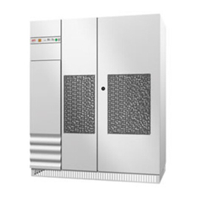
Figure 2 shows the view of the UPS units with the front doors closed.
The opening of the front door, featuring a lock, gives access only to the input, output and bypass
disconnecting switches (if fitted); the UPS unit is supplied together with a key for accessing this
compartment. Fig. 3 shows the disconnecting switch compartment for the various types of UPS units.
The switches (Figures 1 and 3) are:
S1 Rectifier input disconnection switch
S2 UPS output disconnection switch
S3 Manual bypass (Not envisaged in case of UPS set for parallel)
S4 Reserve mains disconnection switch
To access the power compartments, open the front doors and open the board support door: this
operation can be performed using a simple screwdriver - not provided with the UPS unit.
The upper part of the equipment houses the control, measurement and signalling panel (shown in more
detail in Figure 4) and a LED mimic diagram (shown in greater detail in Figure 5).
When the front doors are closed, these are the only accessible components which provide useful
information and carry out all necessary checks.
Even with open doors with lock, the equipment still maintains an insulation standard of IP20, and no
live part is accessible.
Control, measurement and signalling panel.
The control, measurement and signalling panel on the front of the equipment (Figure 2) is shown
in detail in Figure 4 (referred to hereinafter as Signalling).
The signalling panel includes a liquid crystal display (LCD) with 80 characters, and control keys.
During normal UPS operation, signals appear showing the state of machine operation.
Some of these signals are repeated on the Functional diagram (Figure 5) where corresponding LEDs
light up to provide a quick overview of the operation of the different equipment subassemblies.

IV306E Rev. 004 Siel S.p.A. Page 17 of 37 + 12 Tables, 14 Figures + FR
Issued date: 2014-03-24
The appearance of one or more alarms determines the tripping of the acoustic alarm; in these
conditions, the alarms in progress are displayed.
The acoustic alarm can be muted by means of the specific key.
The messages concerning the alarms are organised as follows: the alarm appears in capital block letters
on the top line of the display unit while the bottom line shows the operations to be carried out to reset
the alarm.
A detailed description of the signalling panel functions is given below:
a) Loop view of the UPS status:
the signalling panel displays messages at about every 5 seconds related to the operating status of
all main sections of the UPS.
If one or more alarms trip at the same time, the control logic gives a continuous beep and displays the
alarms in progress.
If the operator mutes the acoustic signal using the key provided, the Signalling will again display all
the UPS messages together with the alarms in progress.
The following are the alarms and signals displayed on the LCD.
Signals
RECTIFIER
1) Rectifier on
BATTERY
2) Battery on float charge
3) Battery on boost charge.
4) Battery voltage OK
INVERTER
5) Inverter on.
6) Inverter-reserve synchronised
7) UPS Master (only when in parallel)
STATIC SWITCH
8) Load on inverter
9) Rerserve OK
10) Load on reserve
Alarms
RECTIFIER
1) Rectifier off
2) Rectifier locked
3) Rectifier over temperature
BATTERY
4) Battery pre-alarm
5) Wrong battery voltage
6) Battery failure
7) Battery Overheating
8) Battery temperature probe fault
INVERTER
9) Inverter overload
10) Phase R over current

IV306E Rev. 004 Siel S.p.A. Page 18 of 37 + 12 Tables, 14 Figures + FR
Issued date: 2014-03-24
11) Phase S over current
12) Phase T over current
13) Inverter over temperature
14) Magnetic units overheating
15) Output filter fault
16) Inverter stopped
17) Inverter output over voltage
18) Inverter-Mains not synchronized
STATIC SWITCH
19) Switching blocked
20) Static switch failure
21) Stand-by not suitable
COMPLETE UPS
22) Emergency UPS activated
23) Back feed protection
24) Manual by-pass inserted (Not for parallel UPS)
25) No Parallel Data Exchange (Not envisaged for single UPS)
26) Ambient overheating
27) Strongly distorting load
28) Preventive maintenance is suggested
29) Preventive maintenance needed
30) Missing isolation (option)
In normal operating conditions (with no alarms),besides the various signals, when the display is
switched on, the UPS Normal Operation message is displayed.
b) Manual display of the UPS status:
during its normal operation - described in item a) above - the signalling can be interrupted by the
operator to see more quickly all messages related to the status and/or alarms. In particular, it is
possible:
- to bring messages forward/back by pushing and releasing keys 2 or 3 together with key 1 as shown in
Figure 4.
- to bring messages forward/back at one second intervals by holding down keys 2 or 3 whilst holding
down key 1 as shown in Figure 4.
c) Display of voltage/current values:
there are three keys (2, 3, 4 in Figure 4) which enable the following information to be displayed
in real time on the signalling panel:
Six UPS output voltages (Phase/Phase and Phase/Neutral)
Six rectifier input voltages (Phase/Phase and Phase/Neutral)
Six reserve mains voltages (Phase/Phase and Phase/Neutral)
Three UPS output currents
Three rectifier input currents
Apparent power, active power, power factor and crest factor of UPS output.
UPS output frequency
Reserve mains frequency
The voltage, the autonomy percentage (percentage of time left until the battery runs down), the battery
current, the battery temperature and the max temperature reached by the batteries
Room temperature and max temperature reached in the room.

IV306E Rev. 004 Siel S.p.A. Page 19 of 37 + 12 Tables, 14 Figures + FR
Issued date: 2014-03-24
d) Communication with special software:
the panel firmware implements a communication protocol with programs that operate on
computers equipped with a EIA-RS232C serial interface; this communication protocol envisages, at
the request of the software with which it dialogues, the transmission of alarms/signals and
measurements of the UPS; the partner software of this dialogue can also pilot all the functions
envisaged by the front panel of the machine.
Siel offers two software programs, which take advantage of all opportunities given by the
communication protocol. These programs, called EDMS and OCSystem3, cater for all possible control
and signalling requirements. In particular, EDMS is compatible with virtually all existing hardware
platforms, whilst the OCSystem3 software offers ample scope for customisation.
To function properly, computers must have a standard EIA-RS232C connection and a monitor with
VGA or higher resolution.
Another option permits monitoring the state of the UPS and performing the shutdown of personal
computer, server and workstation linked to a LAN network.
The option consists in additional hardware which on the one hand links up to the UPS through a serial
interface RS232C and permits network linkup by means of an RJ45 connection.
The protocols implemented on this hardware are HTML and SNMP.
This implies that the status of the UPS can be configured and monitored through any web browser with
Java and the shutdown can be managed of all the machines linked to this network node.
Functional diagram.
The functional diagram on the front of the appliance is shown in figure 5.
FUNCTIONAL DIAGRAM
The functional diagram includes the following signalling lamps (LEDs):
Led 1) - Rectifier on
Led 2) - Near low battery pre-alarm
Led 3) - Inverter on
Led 4) - Load on inverter
Led 5) - Reserve OK
Led 6) - Load on reserve
LED 7) By-pass on (Not functional in case of UPS in parallel)
Description of the back-feed protection sensor
Connection
This type of sensor must be fitted with a four-pole magnetothermal switch, to be supplied by the
customer, and connected in series to the backup supply of the UPS.
When a failure on the static switch occurs, this device enables the release coil of the external switch
(230 VAC with enabled alarm), thus protecting personnel working on the system from potential risks.
The UPS must be connected to the external switch by means of two 4 sqm terminals installed next to
the sectioning elements. If required, the UPS can also be fitted with three additional terminals to
connect the signals of the back-feed protection board. Said terminals correspond to a normally closed
contact (NC), a common contact (C) and a normally open contact (NO) (the tripping of the sensor
causes the relay to be "attracted").
Operation
When the UPS is operated in ordinary mode, the green "R.E. POWER" LED lights on permanently. As
soon as the sensor detects a return of power towards the mains, the red “R.E. ALARM” lights and an
acoustic warning is enabled, while the relay on the back-feed protection board releases the external
This manual suits for next models
18
Table of contents
Other Siel UPS manuals
Siel
Siel SAFEPOWER EVO-HF 200 Guide
Siel
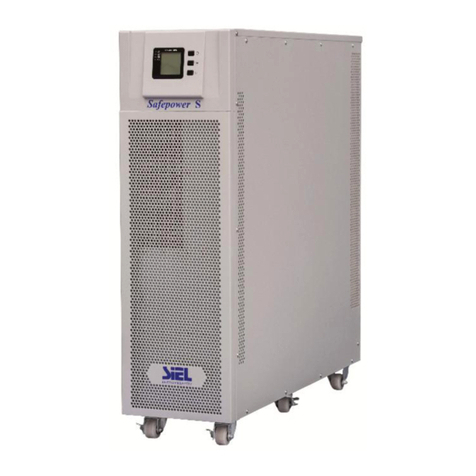
Siel SAFEPOWER-EVO-HF Series User manual
Siel
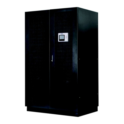
Siel SAFEPOWER S series User manual
Siel
Siel SAFEPOWER SPM User manual
Siel
Siel SAFEPOWER EVO HFT Guide
Siel
Siel Green Point 6 20KVA User manual
Siel
Siel Green Point User manual

Siel
Siel 6kVA User manual
Siel
Siel SAFEPOWER S User manual

Siel
Siel SAFEPOWER S User manual
Popular UPS manuals by other brands

CyberPower
CyberPower 649532815197 Specification sheet

Panamax
Panamax PFPower M1500-UPS-PFP owner's manual

Riello
Riello Sentinel Dual SDH 2200 ER Brochure & specs

Jovyatlas
Jovyatlas JOVYTEC PE Series operating manual
Precision Power
Precision Power PP36L-12K-3 user manual
Forza
Forza FDC-2012R-I user manual

