Siel SAFEPOWER EVO-HF 200 Guide

IV386 Rev.000 SIEL S.p.A.
Data di emissione: 2015-10-02 Pag. 55 di 263 + FR
INTRODUCTION
Thank you for choosing our product.
Our company is highly specialised in the development and production of uninterruptible power supplies (UPS).
The UPS device described in this manual is a high quality product that has been carefully designed and manufactured to
guarantee optimal performance.
This manual contains detailed instructions for product use and installation.
This manual must be stored in a safe place and CONSULTED BEFORE DEVICE USE for proper usage instructions as
well as maximum performance from the device itself.
NOTE: Some images contained in this document are for information purposes only and may not faithfully demonstrate the parts
of the product they represent
ENVIRONMENTAL PROTECTION
Our company devotes abundant resources to analysing environmental aspects in the development of its products. All our
products pursue the objectives defined in the environmental management system developed by the company in compliance with
applicable standards.
Hazardous materials such as CFCs, HCFCs or asbestos have not been used in this product.
Packaging is composed of RECYCLABLE MATERIALS. Dispose of all material in compliance with applicable standards in the
country in which the product is used. Refer to the following table to identify materials:
DESCRIPTION
MATERIAL
Pallet
Wood
(FOR)
Package box
Corrugated cardboard
(PAP)
Protective bag
High density polyethylene
(PE-HD)
Adhesive buffers
Low density polyethylene
(PE-HD)
Bubble wrap
DISPOSING OF THE PRODUCT
The UPS contains internal material which (in case of dismantling/disposal) are considered TOXIC AND HAZARDOUS WASTE,
such as electronic circuit boards and batteries. Treat these materials according to the laws in force, contacting qualified centres.
Proper disposal contributes to respect for the environment and human health.
© The reproduction of any part of this manual, even in part, is prohibited unless authorised by the Manufacturer.
The manufacturer reserves the right to change the product described at any time without prior notice for improvement purposes.

IV386 Rev.000 SIEL S.p.A.
Data di emissione: 2015-10-02 Pag. 56 di 263 + FR
CONTENTS
PRESENTATION 58
FRONT UPS VIEWS 59
USER INTERFACE 61
UPS REAR VIEW 62
UPS CONNECTIONS VIEW 63
AUXILIARY CONTACT SECTION 64
SEPARATE BYPASS INPUT 64
CONTROL PANEL VIEW 65
INSTALLATION 66
INSTALLATION SET-UP 66
INSTALLATION ENVIRONMENT 66
UPS STORAGE 67
ELECTROMAGNETIC COMPATIBILITY 67
OVERVOLTAGE PROTECTION 67
AIR EXCHANGE IN THE BATTERY ROOM 67
REMOVING THE UPS FROM THE PALLET 68
CHECKING THE CONTENTS OF THE ACCESSORIES BOX 70
UPS POSITIONING 70
ELECTRICAL CONNECTIONS 71
CABLE SIZES 71
PRELIMINARY OPERATIONS FOR CONNECTION 71
UPS CONNECTIONS 72
ELECTRICAL SYSTEM CONNECTION DIAGRAMS 73
PROTECTIONS 76
SHORT-CIRCUIT PROTECTION 76
PROTECTION AGAINST BACK-FEED 76
INPUT LINE THERMAL MAGNETIC SWITCHES 76
BATTERY LINE 76
DIFFERENTIAL 77
OUTPUT LINE FUSES/THERMAL MAGNETIC SWITCHES 78
R.E.P.O. 78
AUXILIARY CONTACTS 78
SCHUKO SOCKET 78
OPTIONAL ACCESSORIES 79
EXTERNAL SYNC 79

IV386 Rev.000 SIEL S.p.A.
Data di emissione: 2015-10-02 Pag. 57 di 263 + FR
EXTERNAL TEMPERATURE SENSOR 79
REMOTE PANEL 79
SECOND BATTERY CHARGER 79
REMOTE MAINTENANCE BYPASS 80
PARALLEL CONNECTION 81
TOP CABLE ENTRY 81
EYEBOLTS 81
USE 82
DESCRIPTION 82
FIRST START-UP AND INITIAL SETTINGS 83
SWITCHING ON FROM THE MAINS 85
SWITCHING ON FROM THE BATTERY 85
SHUTDOWN 85
FAN MANAGEMENT 85
GRAPHIC DISPLAY 86
DISPLAY MENU 88
OPERATING MODE 89
MANUAL BYPASS (SWMB) 89
REDUNDANT AUXILIARY POWER ADAPTER FOR AUTOMATIC BYPASS 90
POWER WALK-IN 90
DERATING OF POWER FOR 220/200/208V PHASE-NEUTRAL LOADS 90
UPS CONFIGURATION 91
COMMUNICATION PORTS 93
RS232 AND USB CONNECTORS 93
COMMUNICATION SLOT 93
AS400 PORT 94
ACOUSTIC SIGNAL (BUZZER) 95
SOFTWARE 96
MONITORING AND CONTROL SOFTWARE 96
CONFIGURATION SOFTWARE 96
TROUBLESHOOTING 97
STATUS /ALARM CODES 101
TECHNICAL DATA 105
IV386 Rev.000 SIEL S.p.A.
Data di emissione: 2015-10-02 Pag. 58 di 263 + FR
PRESENTATION
SAFEPOWER EVO-HF 160 –200 series UPS's have been designed using currently available state of the art technology to
ensure maximum performance. The use of new control boards based on multi-processor architecture (DSP +
P inside) and the
adoption of special circuit solutions with cutting edge components provide superior performance. Here are some examples:
ØZERO IMPACT SOURCE: ensures low input distortion, power factor close to one and maximum compatibility with the
generator
ØBATTERY CARE SYSTEM: allows custom handling of batteries for different topologies and continuous monitoring of
the same, thus increasing efficiency and duration
ØSMART INVERTER: provides extraordinary efficiency even at low load rates and a stable output voltage and low
distortion even in the most extreme operating conditions

IV386 Rev.000 SIEL S.p.A.
Data di emissione: 2015-10-02 Pag. 59 di 263 + FR
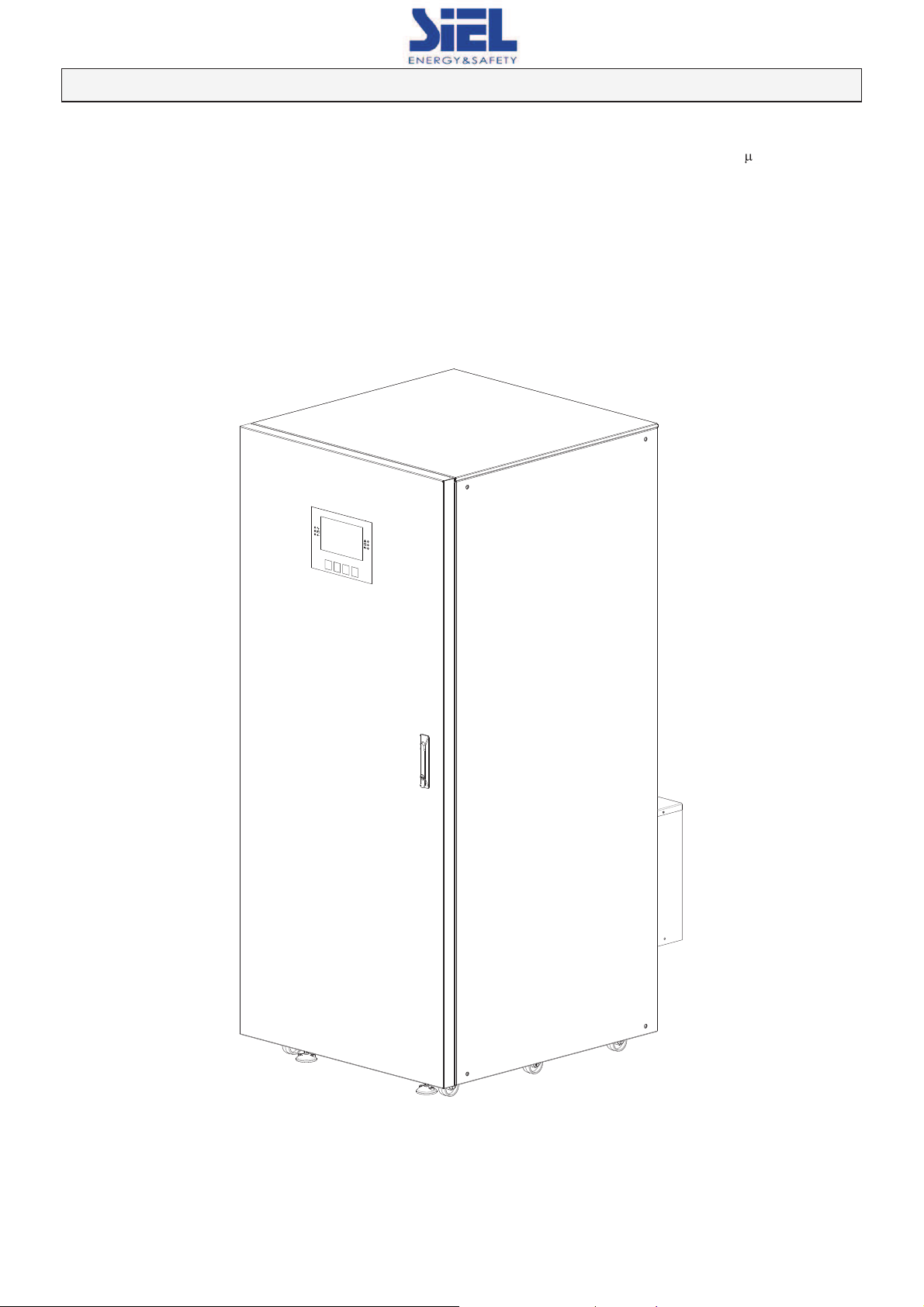
FRONT UPS VIEWS
Control panel with graphic display
UPS feet
Ventilation grille
Wheels for UPS handling
Front door with lock
IV386 Rev.000 SIEL S.p.A.
Data di emissione: 2015-10-02 Pag. 60 di 263 + FR
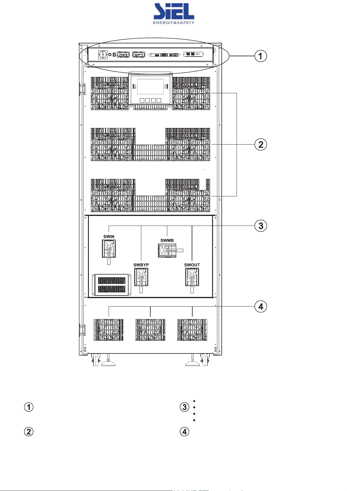
User interface
Left to right:
“SWOUT” Output switch
“SWBYP” Bypass input switch
“SWMB” manual bypass switch
“SWOUT” Output switch
Power module fans
Primary bypass fans
IV386 Rev.000 SIEL S.p.A.
Data di emissione: 2015-10-02 Pag. 61 di 263 + FR
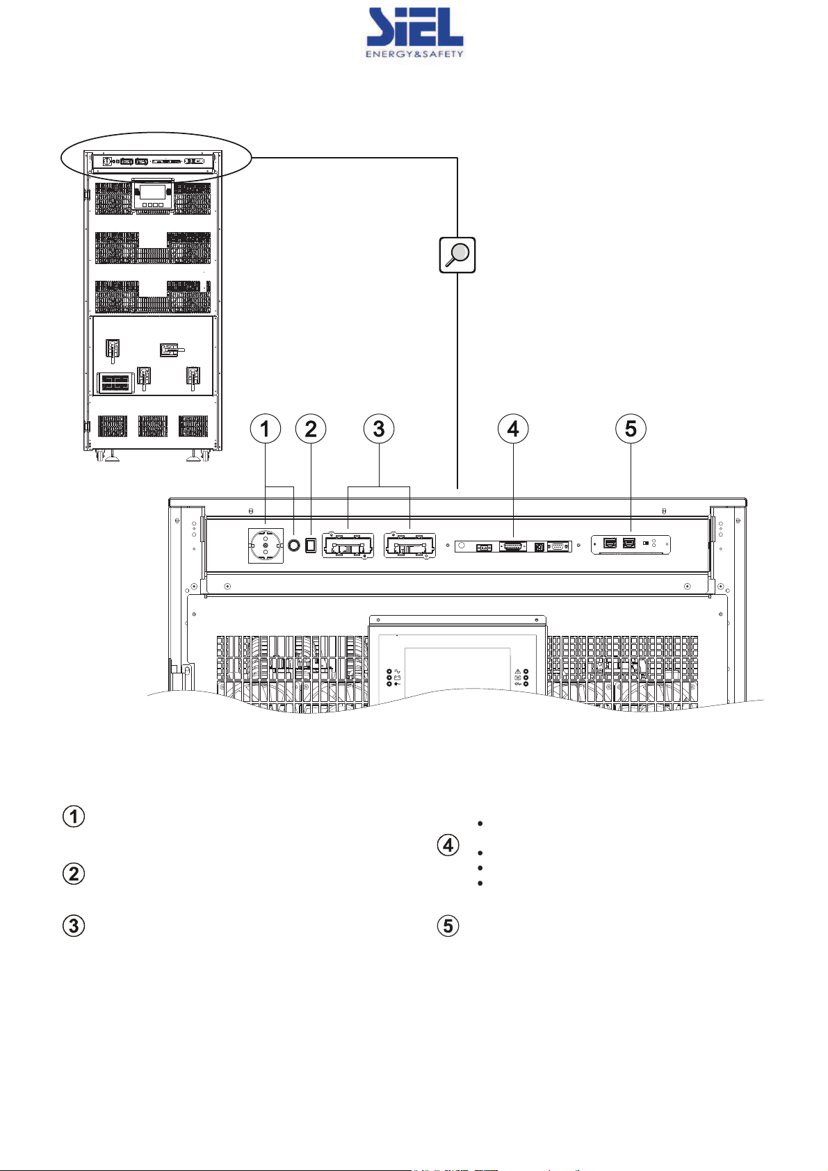
USER INTERFACE
Schuko plug and fuse
Left to right:
“R.E.P.O.
” Remote Emergency Power Off
connector
“AS400” Contacts port
“USB” communication port
“RS232” communication port
“COLD START
” battery start-up button
Slot for accessory communications cards
“UPS Parallel Board
” housing (optional)
IV386 Rev.000 SIEL S.p.A.
Data di emissione: 2015-10-02 Pag. 62 di 263 + FR
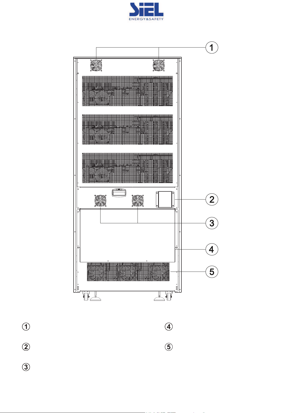
UPS REAR VIEW
Control fans
IN/OUT connection access
Auxiliary contact access
Secondary bypass fans
Battery charger fans
IV386 Rev.000 SIEL S.p.A.
Data di emissione: 2015-10-02 Pag. 63 di 263 + FR
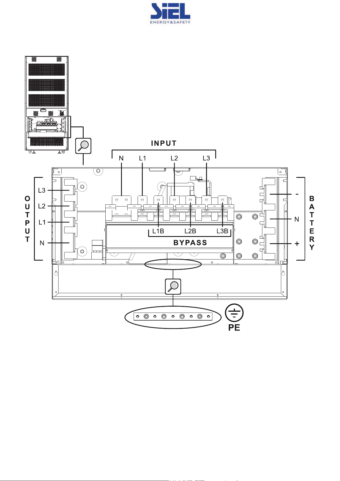
UPS CONNECTIONS VIEW
Remove the IN/OUT access panel to access the UPS terminal board:
BATTERY (+ -
N)
Power connections: BATTERY (+) ,
(-) and NEUTRAL
INPUT (L1 L2 L3 N)
Power connections: INPUT PHASES AND NEUTRAL
BYPASS (L1B L2B L3B)
Power connections: SEPARATE BYPASS PHASES
OUTPUT (L1 L2 L3 N)
Power connections: OUTPUT PHASES AND NEUTRAL
PE
Power connections: GROUND
IV386 Rev.000 SIEL S.p.A.
Data di emissione: 2015-10-02 Pag. 64 di 263 + FR
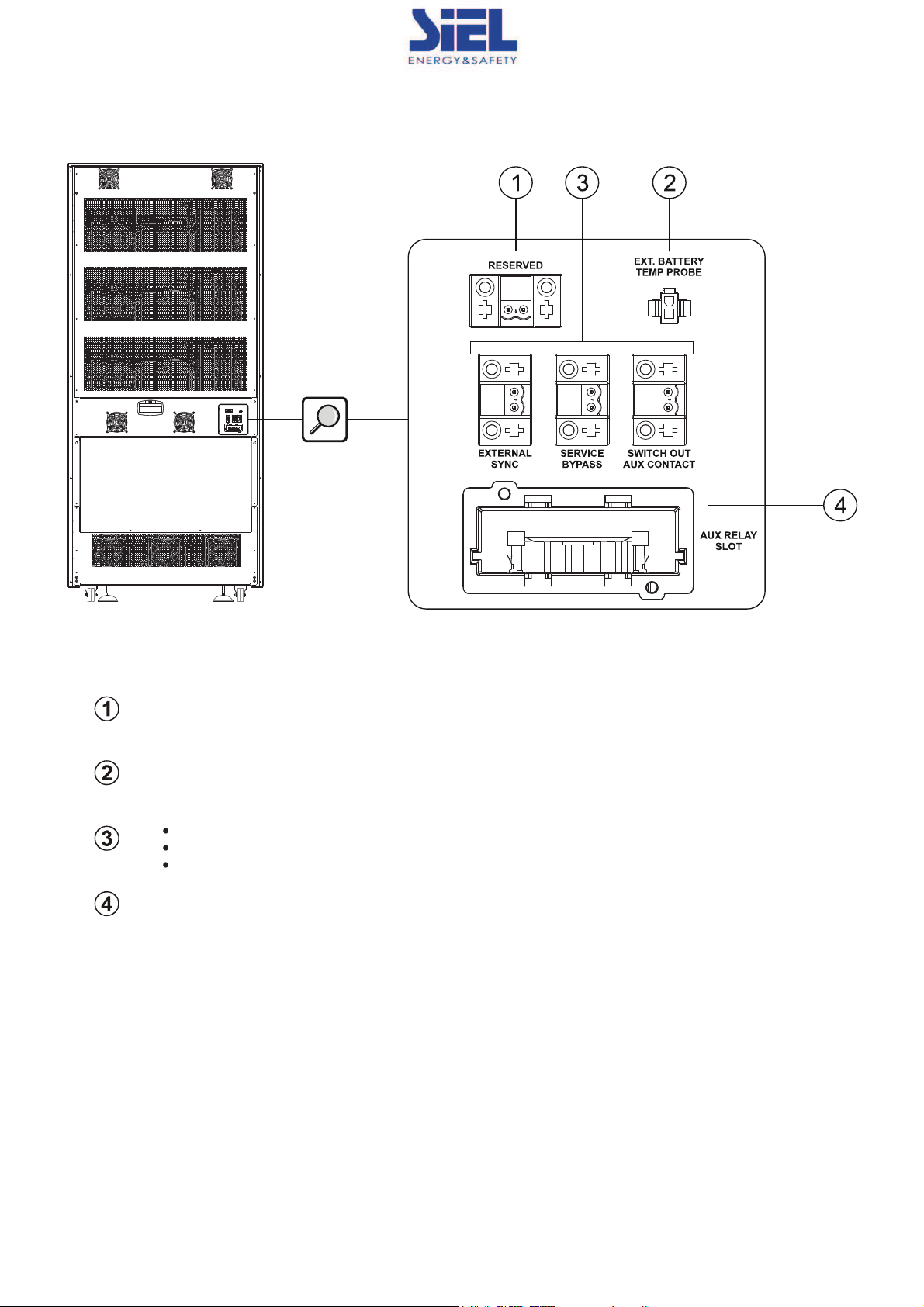
AUXILIARY CONTACT SECTION
RESERVED
: Reserved signal
EXT. BATTERY TEMP PROBE
:Connection for external battery temperature probe
Left to right:
EXTERNAL SYNC: Connection for external synchronization signal
SERVICE BYPASS: Connection for remote auxiliary maintenance bypass
SWITCH OUT AUX CONTACT: Connection for remote auxiliary output switch
AUX RELAY SLOT
: Relay slot
SEPARATE BYPASS INPUT
THIS SERIES OF UPS UNITS CAN BE CONFIGURED IN DUAL INPUT MODE, I.E. WITH THE BYPASS LINE SEPARATE
FROM THE INPUT LINE.
This feature allows for separate connections between the input line and bypass line.
The UPS output will be synchronized to the bypass line in such a way that there will not be any incorrect switching between
push-pull voltages in the event of automatic bypass intervention or manual bypass (SWMB) closing.
IV386 Rev.000 SIEL S.p.A.
Data di emissione: 2015-10-02 Pag. 65 di 263 + FR
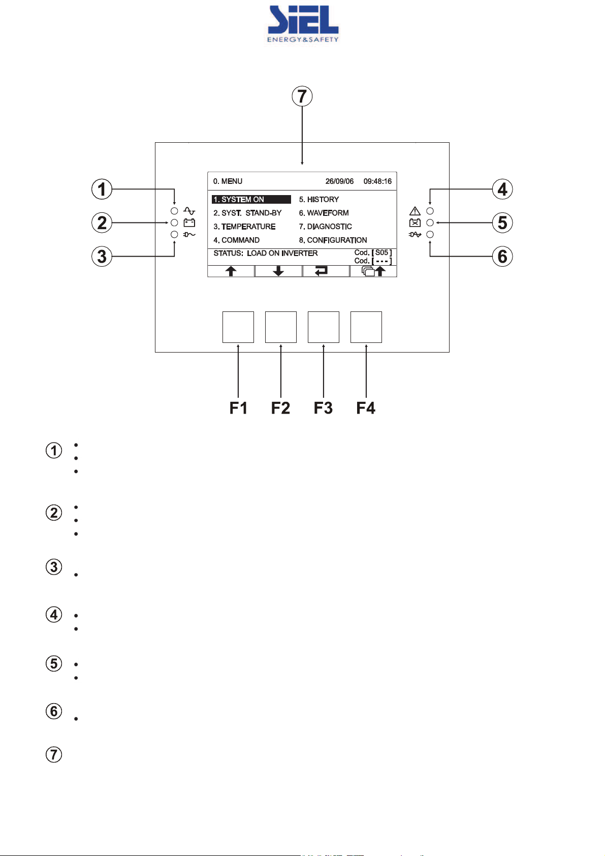
CONTROL PANEL VIEW
Mains operation LED
Steady on: mains operation with good bypass line and synchronised inverter
Flashing: mains operation with bad or disabled bypass line and/or non-synchronised inverter
Flashing in standby: programmed restart function active and mains present
Battery operation LED
Steady on: battery operation
Flashing: battery operation with early low battery or imminent shutdown warning
Flashing in standby: programmed restart function active and mains absent
Load on bypass LED
Steady on: load powered from bypass line
Standby/alarm LED
Steady on: alarm present
Flashing: standby mode
Replace batteries LED
Steady on: replace batteries
Flashing: battery overvoltage alarm
ECO mode LED
Steady on: ECO mode configuration active
Graphic display
F1, F2, F3, F4 = FUNCTION KEYS. Each key's task can be found on the lower part of the display and varies
according to menu.
IV386 Rev.000 SIEL S.p.A.
Data di emissione: 2015-10-02 Pag. 66 di 263 + FR
INSTALLATION
INSTALLATION SET-UP
ALL OPERATIONS DESCRIBED IN THIS SECTION MUST BE PERFORMED BY QUALIFIED PERSONNEL
ONLY.
Our Company assumes no liability
for damages caused by incorrect connections or operations not
contained in this manual.
BEFORE INSTALLING THE UNIT, READ THE PROVIDED “INSTALLATION INSTRUCTIONS”.
This manual, which is included with the UPS, includes important installation
information, including:
Dimensional views of the UPS;
View of the base footprint as an aid to constructing a frame for raising the enclosure;
The cable input position;
The position of the UPS's fans;
Information for sizing the input, output and battery cables;
Hookup information, such as dimensional views of the terminal boards
Installation information, such as the device's power dissipation (kW).
THE UPS HAS WHEEL FOR HANDLING; MAKE SURE THE CABLES ARE LONG ENOUGH TO ALLOW THE
UPS TO BE MOVED FOR
MAINTENANCE
INSTALLATION ENVIRONMENT
When selecting the installation site of the UPS and any Battery Boxes, observe the following notes:
§The UPS / Battery Box must be installed at a suitable distance from walls and other obstacles. For further information,
refer to the included “Installation Instructions”
§avoid dusty environments
§ensure that flooring is flat and able to sustain the weight of the UPS (and Battery Boxes)
§avoid environments that are too narrow which might prevent normal maintenance operations
§relative humidity must not exceed 90%, without condensation
§verify that the room temperature, with the UPS in operation, is maintained between 0 and 40°C
The UPS is able to operate at a temperature between 0 and 40°C. The recommended operating
temperature for the UPS and the batteries is between 20 and 25°C. The actual operating life of the batteries
is 5 years on average at an operating temperature of 20°C. If the operating temperature reaches 30°C, the
operating life is halved.
§avoid positioning the UPS in places which are exposed to direct sunlight or to hot air
To maintain installation room temperature in the above indicated range, waste heat disposal should be provided for (the value of
kW/kcal/h/ B.T.U /h dissipated by the UPS is shown in the table in the included "Installation Instructions").
Methods which can be used include:
§natural ventilation
§forced ventilation, recommended if the external temperature is lower (e.g. 20°C) than the temperature at which you
want to operate the UPS and/or the Battery Box (e.g. 25°C)
§air conditioning system, recommended if the external temperature is higher (e.g. 30°C) than the temperature at which
you want to operate the UPS and/or the Battery Box (e.g. 25°C)

IV386 Rev.000 SIEL S.p.A.
Data di emissione: 2015-10-02 Pag. 67 di 263 + FR
UPS STORAGE
The storage site must meet the following requirements:
Temperature:
-25°÷60°C
Degree of relative humidity:
30÷95% max
ELECTROMAGNETIC COMPATIBILITY
This UPS complies with applicable EMC (Category C3).
CAUTION:
This product is designed for second environment* commercial and industrial applications - it may be necessary during
installation to introduce certain restrictions and take additional measures to prevent disturbances.
Connection to USB and RS232 connectors must be made with the supplied cables or, however, with shielded cables that are no
longer than 3 metres.
(*) Type of environment defined in EMC regulations
OVERVOLTAGE PROTECTION
The UPS has been designed to be powered by an AC mains supply with category 2 voltage spikes. if it connected to an AC
supply with different characteristics or if it is potentially subject to even transitory overvoltage, external protection equipment
must be installed to it.
AIR EXCHANGE IN THE BATTERY ROOM
The room in which the battery box is installed must be provided ventilated so as to keep the concentration of hydrogen
generated during charging within safe limits.
The room should preferably be ventilated naturally; if it cannot be, forced ventilation may be employed.
Standard EN 50272-2 regarding air exchange provides that the minimum aperture must satisfy the following equation:
A = 28 x Q = 28 x 0.05 x n x Igas x C10 (1/10³) [cm²]
where: A=surface free of air input/output opening
Q = air flow to be exhausted [m³/h]
n = number of battery elements;
C10 = battery capacity in 10 hours [Ah]
Igas = gas producing current [mA//Ah]
according to the standard:
Igas = 1 in backup charging for VRLA type batteries (*)
Igas = 8 in fast charging for VRLA type batteries (*)
(*) for open vessel or nickel batteries, contact the battery manufacture for details.
- example calculation
Type of battery: VRLA
Number of elements: 240 (40 mono-blocks)
Capacity: 120Ah
Igas (**): 8 (fast charging)
A = 28 x Q = 28 x 0.05 x n x Igas x C10=28 x 0.05 x 240 x 8 x 120 x 1/10³ = 322 cm2
(**) to increase the safety margin, we take the fast charging condition, well aware that the battery mostly runs in backup
charging mode. Using the backup charging value for Igas would result in a value of one eighth of the above.
The air intake/outlet must be located so as to be most favourable to circulation, e.g.:
-
openings on opposing walls
- with a minimum distance of 2 m if both on the same wall.
IV386 Rev.000 SIEL S.p.A.
Data di emissione: 2015-10-02 Pag. 68 di 263 + FR
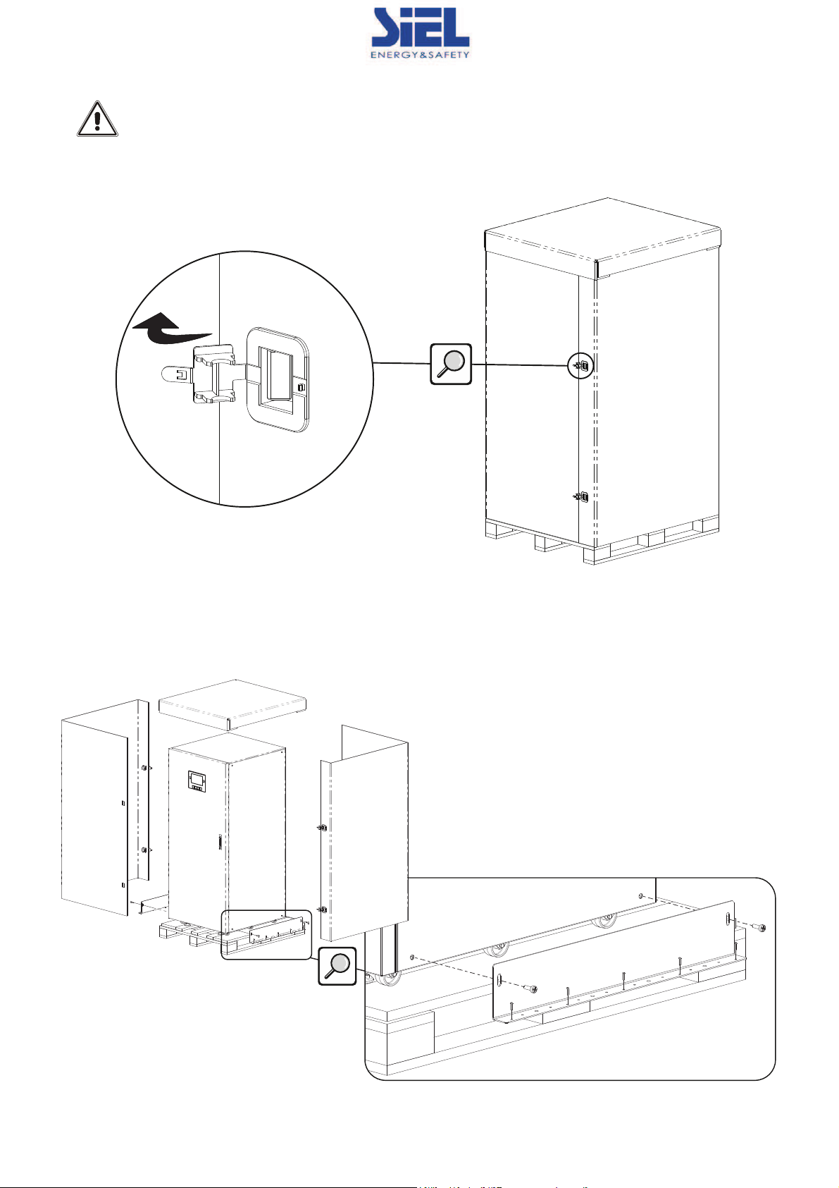
REMOVING THE UPS FROM THE PALLET
CAUTION:
FOLLOW
THE INSTRUCTIONS BELOW TO AVOID PERSONAL INJURY AND/OR
EQUIPMENT DAMAGE.
§
Find the 4 hooks at the sides of the package; lift them to open as shown in the figure.
§
Lift the lid and open the carton.
§
Remove the accessories container.
NOTE: the accessories box may be located inside the packaging or behind the UPS door.
§Remove the 2 brackets securing the UPS to the pallet (2 bolts on the UPS, 5 on the pallet).
IV386 Rev.000 SIEL S.p.A.
Data di emissione: 2015-10-02 Pag. 69 di 263 + FR
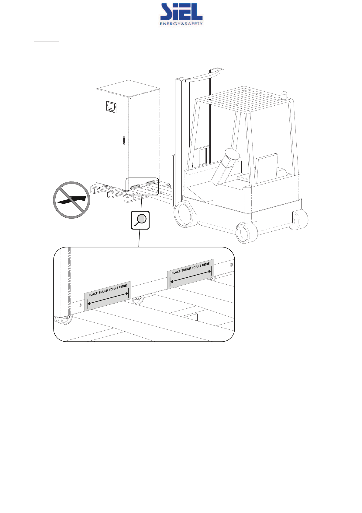
§Lift the UPS off the pallet with a lift truck; take care to position the forks properly.
CAUTION:
Whenever you need to lift the UPS, make sure that the forks are always positioned as indicated by the
labels shown in the figure.
NOTE: retain all packaging materials for future use

IV386 Rev.000 SIEL S.p.A.
Data di emissione: 2015-10-02 Pag. 70 di 263 + FR
CHECKING THE CONTENTS OF THE ACCESSORIES BOX
It is first necessary to check the contents after the packaging has been opened:
user manual, “Installation Instructions”, safety manual, test certificate, safety labels, warranty card, serial cable, door keys.
UPS POSITIONING
When positioning, take into account that:
§the wheels are only to be used for accurate positioning, so for short trips
§plastic parts and the door are not able to act as pushing points or handles
§leave sufficient clearance in front of and behind the device to allow for startup/shutdown and maintenance
§no objects should rest on the upper part of the UPS
OR FURTHER INFORMATION, REFER TO THE INCLUDED “INSTALLATION INSTRUCTIONS”
Once the UPS is in place, secure it with its feet (see "UPS front view").
If necessary, you can reuse the pallet brackets to anchor the UPS to the floor (see figure below). These brackets are not
necessary in normal conditions.

IV386 Rev.000 SIEL S.p.A.
Data di emissione: 2015-10-02 Pag. 71 di 263 + FR
ELECTRICAL CONNECTIONS
CABLE SIZES
For further information, refer to the included “Installation Instructions”
PRELIMINARY OPERATIONS FOR CONNECTION
The following operations are to be performed with the UPS disconnected from the power mains, off and with
all equipment switches open. Before making the connection, open all machine switches and verify that the
UPS is completely isolated from its power sources: AC mains and battery. In particular, check that:
- the UPS input line is completely disconnected
- the separate bypass line (if present) is completely disconnected;
- the external UPS battery line switch/fuses are open
- all UPS switches: SWIN, SWBYP, SWOUT and SWMB in the open position
- check with a Multimeter that there are no dangerous voltages
The first connection to be made is the protective conductor (earth wire), to be connected to the screw
marked PE. The UPS must operate while connected to the earthing system.
The input Neutral must always be connected.
CAUTION: a three-phase 4 wire distribution system is required.
The standard UPS version must be
connected to a 3 Phase + Neutral + PE (ground protection) TT, TN or IT
type power line. Comply with the phase rotation specification.
TRANSFORMER BOXES (optional) are available to convert distribution systems from 3-wire to 4-wire.
CAUTION: in the event of non-linear three-phase loads, the Neutral conductor (N) current can reach a value
up to 1.7 times that of the phase current. Properly size the Input/output Neutral line keeping this fact in mind.
Carefully read instructions contained in the Battery Box manual before connecting batteries.
Check that battery voltage is the same as allowed by the UPS (consult the Battery Box data plate and the
UPS manual)
CAUTION: the maximum length of the connection cables to the Battery Box is 10 metres
IV386 Rev.000 SIEL S.p.A.
Data di emissione: 2015-10-02 Pag. 72 di 263 + FR
UPS CONNECTIONS
Follow the instructions below in order:
§remove the IN/OUT connection access panel on the back of the device (see "UPS rear views")
§hook up the GND cable to the power connection bar marked PE
§connect the input, output and battery cables to the terminal board, following the positions and polarities indicated in
“UPS connections view”. Connect N BATT, N INPUT and N OUTPUT cables to the neutral bar.
IF USING A SEPARATE BYPASS
Follow the instructions below in order:
§remove the IN/OUT connection access panel on the back of the device (see "UPS rear views")
§hook up the GND cable to the power connection bar marked PE
§connect the input, bypass, output and battery cables to the terminal board, following the positions and polarities
indicated in “UPS connections view”. Connect the N BATT, N INPUT N BYPASS and N OUTPUT cables to the neutral
bar.
§Remove the jumpers between the input bars and the bypass bars.
The input and bypass Neutral must always be co
nnected.
The input and bypass lines must be connected to the same potential as of the Neutral.
Once installation operations have been completed and connections verified (see paragraph "First start-up and initial settings"),
restore the IN/OUT connections panel and close the door.
OR FURTHER INFORMATION, REFER TO THE INCLUDED “INSTALLATION INSTRUCTIONS”

IV386 Rev.000 SIEL S.p.A.
Data di emissione: 2015-10-02 Pag. 73 di 263 + FR
ELECTRICAL SYSTEM CONNECTION DIAGRAMS
UPS without neutral connectivity variation
UPS with galvanic input insulation
UPS with galvanic output insulation

IV386 Rev.000 SIEL S.p.A.
Data di emissione: 2015-10-02 Pag. 74 di 263 + FR
UPS without neutral connectivity variation and with separate bypass input
UPS with galvanic input insulation and with separate bypass input
UPS with galvanic output insulation and with separate bypass input
This manual suits for next models
1
Table of contents
Other Siel UPS manuals

Siel
Siel SAFEPOWER S User manual

Siel
Siel 6kVA User manual

Siel
Siel SAFEPOWER-EVO-HF Series User manual

Siel
Siel Green Point User manual

Siel
Siel SAFEPOWER SPM User manual

Siel
Siel Green Point 6 20KVA User manual

Siel
Siel SAFEPOWER EVO HFT Guide

Siel
Siel SAFEPOWER S series User manual

Siel
Siel SAFEPOWER S User manual

Siel
Siel SAFEPOWER S series User manual


