MONTAGEANLEITUNG Arbeitsstromauslöser Z-ASA
1. Beschreibung und Funktion
DerArbeitsstromauslöserZ-ASAist einFernauslöser nachdemArbeitsstromprinzip. DasReiheneinbaugerät istzur Montage
auf DIN-Tragschienen nach EN 50022 vorgesehen, ist 1 TE (17,5 mm) breit, besitzt eine optische Schaltstellungsanzeige
(rot/grün) und kann auch nachträglich an jeden FI/LS Kombischalter, links angebaut werden. FI-Schalter können nicht mit
dem ASAbetätigt werden. Die Fernauslösefunktion ist in einem großen Spannungsbereich möglich. Durch einen zusätzlich
ankoppelbaren Hilfsschalter Z-AHK, Z-NHK ist eine Rückmeldung über die erfolgte Abschaltung erreichbar.
Die Reihenfolge der Montage muss, wie im Bild dargestellt, eingehalten werden, d.h. der Arbeitsstromauslöser muss stets
links am FI/LS und vor dem Hilfsschalter angebaut werden.
Beim Anlegen einer Spannung im zulässigen Bereich spricht derArbeitsstromauslöser praktisch unverzögert an und löst
intern den benachbarten FI/LS Schalter aus. Dabei unterbricht er auch die Zuleitung zur eigenen Magnetauslöserspule und
verhindertdadurchbeiDauerauslösebefehleneine thermischeÜberlastungderAuslöseeinrichtung.WährendeineÜberlänge
desAuslöseimpulsesalsonichtschadenkann,isteineMindestimpulsdauer zursicherenFunktionnotwendig.DieSchalthebel
desASAunddes FI/LSsind mechanischgekoppelt,sodassbeimEinschaltendesFI/LSderKnebeldesASA"mitgenommen"
wird. Bei händischem Ausschalten des FI/LS löst derASA auch ohne Steuerspannung mechanisch mit aus.
ImFallederelektrischenAuslösungdesFI/LSwirdderASAebenfallsinternmechanischausgelöstundgehtindieAUS-Position.
Beieineräußeren mechanischenAusschaltbehinderungdesASASchaltknebelskann dieserdurcheine "Freiauslösung"wie
jeder LS-Schalter trotzdem intern auslösen.
2. Technische Daten
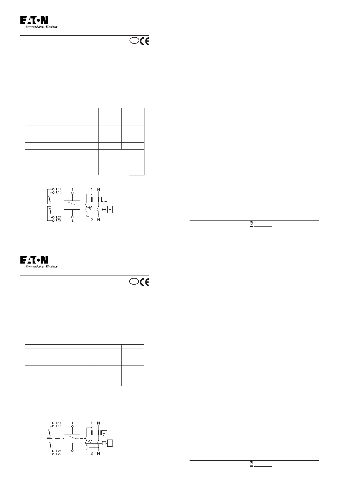
3. Schaltbild
Wechselspannungsbereich ~ 24V 230V
Ansprechgrenze (V) 8 65
Betriebsspannungsbereich (V) 12 - 110 110 - 415
max. Stromaufnahme im Einschaltzeitpunkt (A) 32 1,41 (bei 230V)
Stromflusszeit bei max. Stromaufnahme (ms) 10 -
Gleichspannungsbereich = 24V 230V
Ansprechgrenze (V) 9 88
Betriebsspannungsbereich (V) 12 - 60 230
max. Stromaufnahme im Einschaltzeitpunkt (A) 21 -
Stromzuflusszeit bei max. Stromaufnahme (ms) 2 -
Mindest-Impulsdauer (ms) 15 10
Innenwiderstand (Ohm) 2,19 215
Einschaltdauer (%) 100
Auslösezeit (ms) < 20
Stoßspannungsfestigkeit (1,2/50ms) (kV) 2
Lebensdauer Schaltungen > 4000
Klemmen oben/unten Maul-, Lift/Maul-, Lift
Leiterquerschnitt mm² 1 - 25
Materialstärke Verschienung mm 0,8 - 1,5
4. Montagehinweise
4.1. ASA und CKN in dieAUS-Position bringen.
Die am CKN seitlich dem Z-ASA gegenüberliegenden Klebeflächen fettfrei und sauber machen. Keine
zusätzlichen Klebstoffe verwenden.
4.2. Nach Entfernung der Schutzfolien vom Doppelklebeband des ASA diesen von links an den CKN heranführen
und über Führungshülse positioniert, fest an den CKN andrücken.
4.3. Hilfsschalter Type Z-AHK von links an den ASA heranführen und mit den vormontierten Schrauben des
Hilfsschalters am ASAbefestigen.
Hilfsschalter der Type Z-NHK werden gemäß Montageanleitung rechts an die Schaltgeräte angebaut und haben
auf die Z-ASA-Montage keinen Einfluss.
4.4. Gerätekombination ASA/CKN durch Einschaltknebel des CKN einschalten.
5. Hinweise
Der Arbeitsstromauslöser Z-ASA ist klemmen- und somit verschienungskompatibel mit allen Schaltgeräten. Sowohl die
Blockverschienung,alsauchdiepatentierte SteckverschienungZV könnenverwendetwerden.DieFarbe desSchaltknebels
ist für die 24- und 230V - Ausführung schwarz.
6. Warnungen
DieMontage,derAnschlussunddie InbetriebnahmediesesGerätesdarfnurdurcheineautorisierteElektrofachkrafterfolgen.
VordemArbeitenamGerätunbedingtSpannungabschalten. WirdtrotzBeachtungderMontageanweisungkeineeinwandfreie
Funktion erreicht, kann das Gerät schadhaft sein und ist an den Lieferanten einzusenden.
Eigenmächtige Eingriffe oder Manipulationen sind nicht zulässig und schließen jede Gewährleistung aus.
Der Arbeitsstromauslöser Z-ASAist zum Fernauslösen von Schaltern entwickelt worden und erfüllt bei Beachtung der Mon-
tageanweisungund deszulässigen Spannungsbereichesmit hoherSicherheit seineAufgabe. EineNOT-AUS-Schaltfunktion
istzwartechnischmit demArbeitsstromauslöserrealisierbar. Für dieseAnwendungen werden jedoch vorzugsweisePassiv-
Auslöser, z.B. Unterspannungsauslöser empfohlen.
Die Betätigung des Z-ASA mit Spannungen unter oder über dem im Pkt. 2 angegebenen Betätigungsspannungsbe-
reich kann das Gerät beschädigen und ist daher unbedingt zu vermeiden. Besonders bei der 24V-Type ist auf eine
ausreichende Leistung der Kleinspannungsquelle (Trafo) zu achten. Maximale Stromaufnahme und Dauer siehe
Punkt 2 (techn. Daten).
D
Z-AHK Z-ASA CKN
(zusätzlich möglich)
4. Installation
4.1. Move the ASAand MCB to the OFF-position.
Make sure that the adhesion surfaces of the MCB laterally opposite to the Z-ASA are free from
grease and clean. Do not use any additional adhesives.
4.2. After removing the protective foils from the two-sided adhesive tape on the ASA, move it towards the
CKN from the left and press it firmly onto the LS, CKN positioned by the guide sleeve.
4.3. Auxiliary switch is installed it towards the ASA from the left and mount it onto the ASA by means of the pre-
installed screws of the auxiliary switch.
4.4. Switch on the device combination ASA/MCB by means of the switchon toggle of the MCB.
5. Import Notes
Theshunttriprelease Z-ASAisterminalcompatibleandthusbusbarcompatiblewithallswitchgeardevices.Bothbusbarblocks
and the patented plugin busbars ZV can be used. The colour of the switching toggle of the 24 and 230V versions is black.
6. Warnings
Installation, connection, and starting-up of this protective device is strictly reserved to authorized electrical specialists. In
any case, turn off power before working at the device. If despite taking into account the instructions for installation, flawless
functioningofthedeviceis notachieved, itmaybedefectiveand shouldbe forwardedtothesupplier. Donotattempttomake
any repairs on your own. This would invalidate our warrenty.
The shunt trip release Z-ASA has been developed for remote tripping of Power Line devices and is highly reliable when
taking into account the instructions for installation and the permissible voltage range. It is technically possible to use the
shunt trip release for an emergency off function. However, it is recommended to use passive releases, e.g. undervoltage
releases, for this purpose.
Operating the Z-ASA at voltages above or below the operating voltage range specified in item 2 may damage the device
and therefore must be avoided in any case. Sufficient output of the extra-low voltage source (transformer) must be ensured
particularly for the 24 V type. Maximum current consumption and duration see item 2 (Technical Data).
2. Technical Data
3. Circuit Diagram
INSTRUCTIONS FOR INSTALLATION Shunt Trip Release Z-ASA
1. Function and Description
Theshunttriprelease typeZ-ASAisaremoterelease basedontheworkingcurrentprinciple.Thedeviceformodularinstallation
has been designed for installation on DIN support bars according to EN 50022. It is 1 MU (=17.5 mm) wide, has an optical
switchingpositionindicator(red/green)and canbemountedsubsequentlyon thelefthandsideonto combinedRCBOdevice.
RCD devices cannot be actuated with the ASA. Remote tripping is possible within a wide voltage range.An auxiliary switch
which can be connected additionally permits transmission of a message that switchoff has occurred.
The sequence of installation as shown in the diagram must be observed, i.e. the shunt trip release must always be installed
to the left of the RCBO and upstream of the auxiliary switch.
Whenapplying avoltage withinthepermitted range,theshunt tripreleaseresponds virtuallywithoutdelay andcausesinternal
tripping of the RCBO mounted next to it. At the same time, it cuts the power supply to its own trip coil and thus prevents
thermal overload of the triipping device in case of continuous tripping commands. Consequently, excessive length of the
tripping pulse does not cause damage to the device. However, a minimum pulse length is required for reliable functioning.
The switching toggles of the ASAand RCBO are coupled mechanically in such a way that when the RCBO is activated the
toggleoftheASAismoved simultaneously. In casethe RCBO isswitchedoffmanually, theASAtrips mechanicallyevenif no
controlvoltageispresent. In case ofelectrictrippingof the RCBO, theASAisalso activated internally by mechanicalmeans
and goes to the OFF-position. If an external obstacle prevents the ASAswitching toggle from moving to the OFF-position,
the device may still trip internally like any MCB independently of the toggle position.
AC range ~ 24V 230V
Responding limit (V) 8 65
Operating voltage range (V) 12 - 110 110 - 415
Max. current consumption at the moment of switching on (A) 32 1,41 (at 230V)
Duration of current flow at max. current consumption (ms) 10 -
DC range = 24V 230V
Responding limit (V) 9 88
Operating voltage range (V) 12 - 60 230
Max. current consumption at the moment of switching on (A) 21 -
Duration of current flow at max. current consumption (ms) 2 -
Minimum pulse duration (ms) 15 10
Internal resistance (Ohm) 2,19 215
Duty (%)
100
Tripping time (ms) < 20
Peak withstand voltage (1,2/50ms) (kV) 2
Service live operating cycles > 4000
Upper/lower terminals open mouthet, lift/
Conductor cross section mm² 1 - 25
Busbar thickness mm 0,8 - 1,5
Z-AHK Z-ASA CKN
(additional possible)
GB
Instruction Leaflet
Montageanweisung
Notice d’installation
Instrucciones de montaje
Istruzioni per il montaggio
Инструкция по монтажу
Montagehandleiding
Montagevejledning
Οδηγίες εγκατάστασης
Instruções de montagem
Monteringsanvisning
Asennusohje
Návod k montáži
Paigaldusjuhend
Szerelési utasítás
Montāžas instrukcija
Montavimo instrukcija
Instrukcja montażu
Navodila za montažo
Návod na montáž
Монтажни инструкции
Instrucţiuni de montaj
Upute za montažu
Kullanma Talimatı
Упутство
Intruksjonsblad
Монтажна інструкція
Eaton Industries (Austria) GmbH, Eugenia 1, 3943 Schrems, Austria MA-Z-ASA.indd / 11.2018e / IL019165ZU / 150501259
© 2018 by Eaton Industries (Austria) GmbH, www.eaton.eu/documentation All Rights Reserved / Printed in Austria
www.eaton.com/recycling
1
Eaton Industries (Austria) GmbH, Eugenia 1, 3943 Schrems, Austria MA-Z-ASA.indd / 11.2018e / IL019165ZU / 150501259
© 2018 by Eaton Industries (Austria) GmbH, www.eaton.eu/documentation All Rights Reserved / Printed in Austria
www.eaton.com/recycling


 Manual")


036BCSNLSOND533 Series Manual")


