Siemens Energy SpecTRON 10 User manual

Unrestricted
siemens-energy.com
SpecTRON
10 & 10+
Installation, Operation Manual
Document No: DOC0074
Document No:
DOC0074
Issue Date:
22/10/2021
Revision:
10
Page:
2 of 53
Unrestricted
Foreword
Thank you for purchasing a Siemens Energy SpecTRON 10 Mk. II or 10+ product. The information that
follows is an overview of the protection, storage, shipment, unpacking, deployment and maintenance
instructions forSpecTRON 10 Mk II and 10+ products.
Siemens Energy recommend the termination and installation of all equipment only be undertaken by
suitably trained and qualified personnel.
Revision Summary
This page records the revision status of the entire document and its authorisation for issue. When a page or
pages of the document are revised, the number of the page(s) affected will be entered in the Page(s)
Affected/Remarks column and a vertical margin line will appearagainst the latest amended text.
Rev
Compiled by
Approved by
Issue Date
Page(s) Affected/Remarks
0
C. Plant
W. Barrett
13/08/12
First Issue
1
C. Plant
W. Barrett
20/09/12
Bundle jumper bend radius changed to 500 mm, updated notes on
clamping to clarify penetrator requirements
2
C. Plant
W. Barrett
12/11/12
Section 6.1 - Add maximum clamping distance (2 meters)
Section 8.1 - Clarify that receptacle should only be exposed when
changing from plug to dummy plug and that total exposure time is 28
days in total+ Section 8.1 - Clarify that plug can be left unmated as
long as required
Section 8.2.2 - Clarify that SpecTRON 10 connectors are not isolated
from CP by design
Section 8.4.1 - Clarify cleaning and maintenance instructions
3
N. Knight
K. Higgs
04/09/13
Front Cover –Updated.
Section 1 –Add ‘In Line’ to PCE-B62 and PCE-A74 connector
descriptions.
Section 1 –Add Right Angle connectors, PCE-A74, PCE-B64 and PCE-
B76.
Section 4 –Add image of Right Angle connector lifting positions.
Whole document –Change all ‘Tronic’ references to ‘Siemens Energy
Connectors’.
4
M. Gretton
B. Leach
07-03-14
1. –add product safety information to introduction
2. –add the HSE section
11. –add the punch list to document
5
K.Mutton
W.Barrett
28.4.14
New Front cover design added
6
M. Gretton
B. Leach
04/06/14
Section 2. –HSE section comment about receptacle connectors added
7
S. Roberts
D. Church
26/06/14
Section 9.2 amended, reference to CP strap being 30mm2is incorrect.
CP strap corrected to be 16mm2.
8
J. Keith
M. Earnshaw
13/09/17
Major update to document.
Technical specification update to include more data on cable and
hose.
Information added for the packing, lifting and handling of Bundled
harnesses.
Section 11 added for cleaning of protective caps and receptacles post
SIT and deployment.
Connector storage conditions updated.
Document No:
DOC0074
Issue Date:
22/10/2021
Revision:
10
Page:
3 of 53
Unrestricted
Umbilical section created that outlines testing, handling and umbilical
receptacle orientation.
Installation section updates for mount orientations and hose routing.
SIT section updated for hose routing in SIT and when connector
cleaning is required.
Added tolerance to OD of Hose in section 3.3.1.
Added cable clamp strength rate to section 6.
Updated document to latest Siemens template.
09
N.Williamson
M.Earnshaw
27/10/20
Section 3.3: Updated weight values for AquaTRON 200 hose
harnesses (single and bundled) with FF70 and FF150 cable.
Added info on requirement for hose extenders on AquaTRON
harnesses longer than 45m.
Section 6: Corrected rating of cable clamp and hose in lifting and
handling section. Clarified that statement regarding 5m is in air –i.e.
not applicable for deployment in water.
Section 7.1: Clarified that connector mounting screws must be
tightened to a dead stop before being torqued.
Section 9.1: added info on max unsupported length of harnesses in
water.
10
C. Plant
N.Williamson
26/10/2021
General: Updated to Siemens Energy branding and product safety
focused template, content migrated across.
Change maximum length of unsupported bundled harness from 25 m
to 75 m.

Document No:
DOC0074
Issue Date:
22/10/2021
Revision:
10
Page:
4 of 53
Unrestricted
Contents
1PRODUCT SCOPE...............................................................................................7
1.1 Permeguard™ Wet Mate Receptacle Connector ...........................................7
1.2 Product Certification .................................................................................7
1.3 Contact details..........................................................................................7
1.4 Product advice label ..................................................................................8
1.5 Product marking .......................................................................................9
1.6 CE label/marking.......................................................................................9
2PRODUCT SAFETY ...........................................................................................10
2.1 Action-related warnings...........................................................................10
2.2 Intended use ..........................................................................................10
2.3 General safety information ......................................................................11
2.4 Related documents .................................................................................14
3ABBREVIATIONS .............................................................................................16
4SPECIFICATION AND RESIDUAL HAZARDS ..........................................................18
4.1 Connector General Specification ...............................................................18
4.2 Misalignment capability of wet mate connectors........................................18
4.3 Hose Specifications .................................................................................19
4.4 Cable Specifications.................................................................................19
4.5 Other specifications ................................................................................19
4.6 Environmental, disposal and recycling .......................................................21
4.7 Personal protective equipment (PPE) ........................................................21
5PREPARING PRODUCT FOR USE ........................................................................22
5.1 Safety precautions before installation .......................................................22
5.2 Unpacking ..............................................................................................24
5.3 Safe disposal of packaging........................................................................25
5.4 Lifting ....................................................................................................26
5.5 Installation and assembly.........................................................................27
5.6 Storage and protection ............................................................................30
5.7 Repackaging to prevent damage in transport .............................................32
6OPERATION OF PRODUCT ................................................................................33
6.1 Energising Wet Mate Pair.........................................................................33
6.2 Deployment ...........................................................................................33
6.3 Hose Management and Routing................................................................34
6.4 Umbilical Power Core Management and Termination .................................39

Document No:
DOC0074
Issue Date:
22/10/2021
Revision:
10
Page:
5 of 53
Unrestricted
6.5 Connecting and Disconnecting Wet Mate Pair ............................................41
6.6 Quick references .....................................................................................42
6.7 Testing...................................................................................................43
6.8 Disposal of waste products ......................................................................45
7USER INFORMATION .......................................................................................46
7.1 Normal and faulty/dangerous operation ...................................................46
7.2 Cathodic Protection.................................................................................46
7.3 Troubleshooting (FAQ’s) ..........................................................................47
8PRODUCT MAINTENANCE ................................................................................48
8.1 Connector Cleaning and Drying .................................................................48
8.2 Product maintenance (skilled persons) ......................................................50
9CUSTOMER COMMENTS/FEEDBACK..................................................................52
Tables
Table 1 - SpecTRON 10 Mk. II and 10+ Product Certification............................................................7
Table 2 - Contact Details ................................................................................................................7
Table 3 - SpecTRON 10 Mk. II and 10+ Connectors General Specification.......................................18
Table 4 - SpecTRON 10 Mk. II and 10+ Connector Misalignment Capability....................................18
Table 5 - SpecTRON 10 Mk. II and 10+ Hose Specifications............................................................19
Table 6 - SpecTRON 10 Mk. II and 10+ Cable Specifications ...........................................................19
Table 7 - Troubleshooting product contact details ........................................................................47
Illustrations
Figure 1 - Product Advice Label ......................................................................................................8
Figure 2 - Example Etching for SpecTRON 10 Mk. II and 10+ Products ..............................................9
Figure 3 - Example harness marking ...............................................................................................9
Figure 4 - SpecTRON 10 harness in packaging ...............................................................................22
Figure 5 - Reinforced Bundled Harness Box...................................................................................23
Figure 6 –Specific Packing for Bundled Harness............................................................................23
Figure 7 - SpecTRON 10 and 10+ Protective Caps ..........................................................................24
Figure 8 - Allowable lift positions (In Line Connectors)..................................................................26
Figure 9 –Allowable lift positions(Right Angle Connectors)..........................................................27
Figure 10 –Fixed Inline mount orientations...................................................................................28
Figure 11 –Fixed Right Angle mount orientations.........................................................................28
Figure 12- Compliant Inline Mount Type 1 Orientations................................................................29
Figure 13- Compliant Inline Mount Type 2 Orientations................................................................29
Figure 14- Compliant Right Angle Mount Orientations..................................................................29
Figure 15 - AquaTRON (left) and Gorilla (right) hoses at to minimum bend radius..........................34

Document No:
DOC0074
Issue Date:
22/10/2021
Revision:
10
Page:
6 of 53
Unrestricted
Figure 16 - Incorrectly routed AquaTRON (orange) and Gorilla (yellow) Hose ................................35
Figure 17 - Immediate fall in routing.............................................................................................35
Figure 18 - Hose kink due to immediate fall in routing and weight application...............................35
Figure 19 - Plate Former...............................................................................................................36
Figure 20 - ‘U’ Former..................................................................................................................36
Figure 21 - ‘L’ Former..................................................................................................................36
Figure 22 - Permanent fixed ‘U’ former ........................................................................................37
Figure 23 - Minimum clamp spacing from connector.....................................................................37
Figure 24 - Potential clamping of hose on compliant connector.....................................................38
Figure 25 - Example of temporary hose support during SIT............................................................38
Figure 26 - Example of support for immediate fall in hose routing.................................................39
Figure 27 - Fabricated stand with former used for hose support....................................................39
Figure 28 - Umbilical Receptacle Side on Termination (outside UTA).............................................40
Figure 29 - Umbilical Receptacle orientations...............................................................................40
Figure 30 - Umbilical clamping position........................................................................................41
Figure 31 - Disassembled receptacle protective cap......................................................................49
Figure 32 –Receptacle Components for drying and cleaning.........................................................49
Figure 33 - Receptacle Pin tip recess............................................................................................49
Figure 34 - Receptacle pin contact area as supplied ......................................................................50
Figure 35 - SpecTRON 10 and 10+ Power Washing Locations.........................................................51

Document No:
DOC0074
Issue Date:
22/10/2021
Revision:
10
Page:
7 of 53
Unrestricted
1PRODUCT SCOPE
This manual includes information on the following SpecTRON 10 and 10+ connectortypes:
- SpecTRON 10 Mk. II and 10+ Jumpers, with both Right Angle and Inline Glands
- SpecTRON 10 Mk. II and 10+ Wet Mate Plug
- SpecTRON 10 Mk. II and 10+ Permeguard™ Wet Mate Receptacle Connector
- SpecTRON 10 Mk. II and 10+ Penetrator
- SpecTRON 10 Mk. II and 10+ Test Jumpers
1.1 Permeguard™ Wet Mate Receptacle Connector
SpecTRON 10 and 10+ wet mate receptacle connectors use Siemens Energy’s Permeguard™ wet mate
receptacle connector to provide industry leading robustness and reliability by preventing direct seawater
contact with insulation.
1.2 Product Certification
Standard
Description
SEPS SP-1001
Power connectors,penetrators and jumper assemblies with rated voltage from 3
kV (Umax = 3,6 kV) to 30 kV (umax = 36 kV)
Note: Self-certified via in-house testing.
Table 1 - SpecTRON 10 Mk. II and 10+ Product Certification
1.3 Contact details
For additional information or questions regards the products visit the Siemens Energywebsite www.siemens-
energy.com/subsea or contact the following:
Department
E-mail address
Product Safety Officer
subsea.connectors.productsafety.gb@siemens-energy.com
Technical Support
connectortechnicalsupport.gb@siemens-energy.com
Service (Site Team)
susultlcmsupport.gb@siemens-energy.com
Sales
connectorsales.gb@siemens-energy.com
Table 2 - Contact Details
Document No:
DOC0074
Issue Date:
22/10/2021
Revision:
10
Page:
8 of 53
Unrestricted
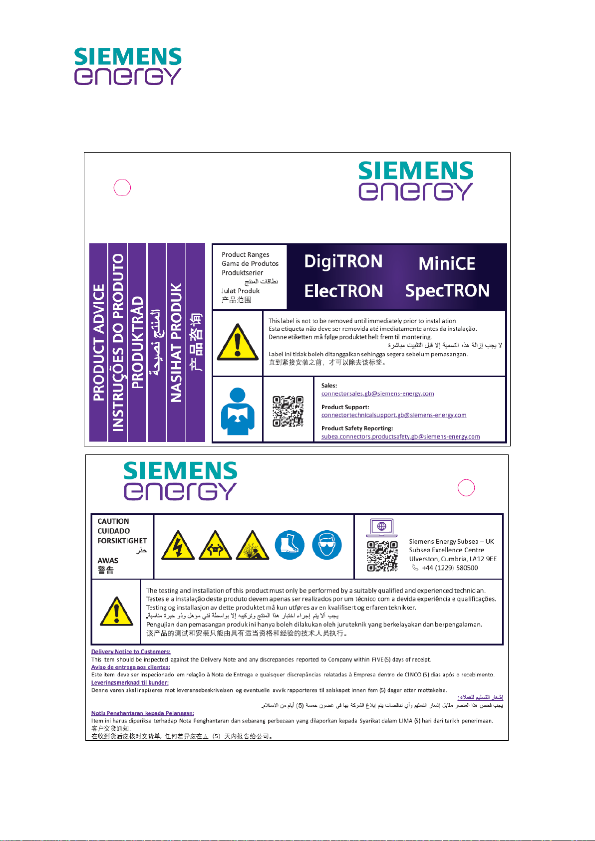
1.4 Product advice label
The following product advice label is supplied with all Siemens Energy subsea connector products.
Figure 1 - Product Advice Label

Document No:
DOC0074
Issue Date:
22/10/2021
Revision:
10
Page:
9 of 53
Unrestricted
1.5 Product marking
1.5.1 Connectors and Penetrators
Figure 2 - Example Etching for SpecTRON 10 Mk. II and 10+ Products
Siemens Energy SpecTRON 10Mk. II and 10+ connectors and penetrators are laser marked on the gland body
with the Siemens Energy part number, unique serial number, and product rating information. Additionally,
connector front-ends are also marked with their part number and unique serial number to aid traceability
during manufacturing.
1.5.2 Harnesses
Harnesses are also marked with the Siemens Energy part number and unique serial number as shown in
Figure 3. Client and projectspecificinformation is also usually added to these labels. Labels are typically black
text on a yellow background underneath clear heat shrink. Typically, labels are located at each end of the
harness and centrally.
Figure 3 - Example harness marking
1.6 CE label/marking
SpecTRON 10 Mk. II and 10+ is exempt from any current requirement for CE marking. Siemens Energy
continue to monitor European and International requirements for applicability to the SpecTRON 10 Mk. II
and 10+ product range.

Document No:
DOC0074
Issue Date:
22/10/2021
Revision:
10
Page:
10 of 53
Unrestricted
2PRODUCT SAFETY
Siemens Energy Subsea recommends the termination of all equipment shall only be undertaken by trained,
suitably qualified and experienced personnel(SQEP) i.e. competent person.
2.1 Action-related warnings
Classification of action-related warnings
The action related warnings are classified in accordance with the severity of the possible danger using the
following warning signs and signal words:
Warning symbols and signal words
Danger!
Imminent dangerto life or risk of severe personalinjury
Danger!
Risk of death from electric shock
Warning.
Risk of minor personalinjury
Caution.
Risk of material or environmentaldamage
2.2 Intended use
Following installation, commissioning, and deployment of product, pleasecompleteand return theCustomer
Comments/Feedback form (Section 9). Please e-mail completed form to the Product Safety Officer at
subsea.connectors.productsafety.gb@siemens-energy.com.
There is a risk of injury or death to the user or others, orof damage to the product and otherproperty in the
event of improper use or use for which it is not intended.
The product is intended as a subsea high voltage electrical connector, for use by suitably trained personnel
in industrial applications only.
Intended use includes the following:
- Observance of the installation and operating instructions included for the product and any other system
components.
- Compliance with all inspection and maintenance conditions listed in the instructions.
- Use of all recommended tooling appropriate for specific tasks.
- All activities to be undertaken by a competent person (see 2.3.1for definition).
Any other use that is not specified in this document or covered in installation and operating instructions, or
beyond that specified in this document shall be considered improperuse.
Document No:
DOC0074
Issue Date:
22/10/2021
Revision:
10
Page:
11 of 53
Unrestricted
2.3 General safety information
2.3.1 Installation by competent persons only
The installation, inspection, maintenance and repair of the product shall be undertaken by trained, suitably
qualified and experienced personnel (SQEP) i.e. competent person, to carry out a specifie d activity.
Installation, inspection, maintenance and repair of products by untrained and deemed non -competent
persons could invalidate the product warranty.
For further information contact Service (Site Team) susultlcmsupport.gb@siemens-energy.com.
2.3.2 Danger caused by improper operation and foreseeable misuse
Improper operation and foreseeable misuse may present a danger to you and others and cause material
damage. Carefully read the enclosed instructions and all other applicable documents, particularly the
“Safety” section and the warnings.
Danger! Risk of death from electric shock if user dismantles/incorrectly re-assembles/incorrectly
re-terminates product (foreseeable misuse).
- Maintenance, disassembly, re-assembly and termination activities must only be carried out by
a competent person.
Danger! Risk of death from electric shock if shuttle pins are depressed e.g. with a screwdriver
when plug is live.
- Maintenance and testing activities must only be carried out by a competent person.
- Correct tools must always be used.
Danger! Risk of imminent danger to life, risk of severe personal injury caused by a shuttle pin
projectile due to damage caused to shuttle pins e.g. with a screwdriver (foreseeable misuse).
- Maintenance and testingactivities must only be carried out by a competent person.
- Correct tools must always be used.

Document No:
DOC0074
Issue Date:
22/10/2021
Revision:
10
Page:
12 of 53
Unrestricted
2.3.3 Risk of death due to electrocution
Danger! Risk of death from electric shock due to exposed live pins, e.g. factory or top-side system
test and unmated receptacle is energised, e.g. by diver subsea.
- Ensure all test procedures are followed.
- Receptacles must be mated to a wet mate or test plug before energisation
- Communication channels and protocols are observed.
Danger! Risk of death from electric shock from any exposed conductors due to stored electrical
energy, e.g. capacitance of cable or elsewherein the system.
- Ensure all procedures are followed.
- Allow sufficient time for discharging of items after testing
Danger! Risk of death from electric shock from test connectors. Live parts can be exposed by
disassembly without a tool (e.g. termination sleeves are accessible and can be removed). Also
exposed cable conductors at free end of test connectors, and unscreened cables in some
terminations.
- Ensure all test procedures are followed.
- Receptacles must be mated to a wet mate or test plug before energisation
- Communication channels and protocols must be observed.
Danger! Risk of death from electricshock if product is terminated incorrectly by 3rd party e.g. loose
conductortouching metal body, or live wire terminated to metal body in error.
- Installation/termination activities must be carried out by a competent person
Danger! Risk of death from electricshock due to metalbody of connectornot being earthed during
test and connector having earth fault (e.g. conductor touching metalwork) during electrical
testing.
- Ensure all testing of products both factory and deployed in-field have been completed by
competent persons.
Danger! Risk of death from electric shock or severe personal injury through burning from de-
mating live conductors by hand.
- Ensure all procedures are followed formating/de-mating connectors.
2.3.4 Risk of injury and material damage due to maintenance and repairs carried out
incorrectly or not at all
Maintenance work orrepairs on the products shouldonly be carried out by a competent person. Faults and
damage should be immediately rectified by a competent person. Adhere to the maintenance intervals
specified.
Danger! Risk of imminent dangerto life, risk of severe personalinjury from burning and material
damage from ohmic heating in short-circuit condition or high over-currents.
- Ensure all testing of products both factory and deployed in-field have been completed by
competent persons.
Danger! Risk of imminent danger to life, risk of severe personalinjury caused by released pressure
and or projectile due to incorrectly installed pressure retaining product, e.g. during system
pressure test (e.g. SpecTRON 10or 10+ penetratorfitted with wrong/insufficient screws or seals).

Document No:
DOC0074
Issue Date:
22/10/2021
Revision:
10
Page:
13 of 53
Unrestricted
- Ensure all product assembly and testing activities are completed by competent persons.
Danger! Risk of imminent danger to life, risk of severe personalinjury to persons with pacemakers
or implantable cardioverter-defibrillators (ICDS) from electromagnetic interference (EMI)e.g. high
frequency testing with large load currents.
- Ensure all testing of productsboth factory and topside are not conductedby orin the presence
of persons with pacemakers orICDS.
Danger! Risk of severe personaleye injury due to pressurised oilsquirting out of damaged hose or
removalof fill/vent screw.
Ensure all testing of products both factory and deployed in-field have been completed by
competent persons.
Warning. Risk of eye/bodily injury caused by releasedpressureduring productdisassembly,in the
event of retrieval from subsea with a fault that causes depth pressure to be trapped inside the
product.
- Ensure all product disassembly activities are completed by competent persons in accordance
with relevant procedures and using relevant personalprotective equipment (PPE).
Warning. Risk of bodily injury caused by pressure retainingparts becoming projectile due to user
over-pressurising the system, e.g. during Site Installation Test (SIT).
- Ensure all product SIT activities are completed by competent persons in accordance with
relevant procedures.
- All pressure testing of SpecTRON 10 Mk. II and 10+ products must be undertaken by a
competent person.
- Installation of SpecTRON 10 Mk. II and 10+ penetrators must be undertaken by a competent
person.
2.3.5 Risk of injury and material damage due to manual handling
Manual handling, lifting and carrying are known to be one of the largest contributors to occupational ill-
health. Ensure mechanical handling aids are used wherever possible to avoid manual handling. Where
manual handling is considered appropriate for the task, safe lifting guidelines must be followed, e.g. adopt
correct posture, consider team lifting, employ safe lifting technique, etc. Only competent persons are
permitted to perform tasks without supervision, if in doubt, ask.
Document No:
DOC0074
Issue Date:
22/10/2021
Revision:
10
Page:
14 of 53
Unrestricted
Warning. Risk of musculoskeletal injury from hand-mating connectors with high mate/de-mate
force and/or connector rapidly fires out during de-mate due to high shuttle spring force, e.g.
factory/topside testing.
- Ensure all product testing activities are completed by competent persons in accordance with
relevant procedures.
- Ensure mechanical handling aids are used whereverpossible to avoid manualhandling.
- Where manual handling is considered appropriate for the task, safe lifting guidelines must be
followed, e.g. adopt correct posture, consider team lifting, employ safe lifting technique, etc.
Warning. Risk of musculoskeletalinjury from manual handling of heavy products.
- Ensure mechanical handling aids are used whereverpossible to avoid manualhandling.
- Where manual handling is considered appropriate for the task, safe lifting guidelines must be
followed, e.g. adopt correct posture, consider team lifting, employ safe lifting technique, etc.
- Only competent persons are permitted to perform tasks without supervision, if in doubt ask.
Warning. Risk of bodily injury from heavy product falling during lift with machinery.
- Ensure machinery/slings used have been tested and are within their expiry date.
- Safe lifting guidelines must be followed, e.g. lifting plan, banksman, etc.
- Correct lifting points must be identified and used.
- Only competent persons are permitted to perform tasks without supervision, if in doubt ask.
Warning. Risk of minor personalinjury to persons with sensitivities to mineral, silicone or synthetic
ester based oils.
- Wear appropriate hand protection when handling products, mineral, silicone or synthetic
ester based oils.
Warning. Risk of minor personalinjury and material damage due to slips, trips and falls.
-Good housekeeping avoids slips, trips and falls, keep all work areas clean and tidy.
2.4 Related documents
Installers shall perform a full site risk assessment and put into place all necessary steps and procedures to
comply with applicable area, regional, national and internationalhealth and safety legislation, e.g. The Health
and Safety at Work Act (HASAWA) in the United Kingdom (UK) and ensure safety of themselves and others
regarding manual handling and working at height requirements.
During the product installation (and any subsequent work)it will be necessary to employ caution. Allinstallers
and operatives involved from unloading the product until it is deployed in its final installed location must
exercise a fullduty of care for themselves and others regarding safety. Whenlifting and handling this product,
operatives should employ assistance if required. In certain situations, it may be necessary to use mechanical
handling aids. Take care to avoid trip hazards, slippery or wet surfaces.
Employers and installers should refer to the Health and Safety Executive (HSE) web site in the UK for full
advice and manual handling assessment charts (MAC) tool.
In addition, where no specific instructions are given then reference shall be made, but not restricted to,
where applicable, British Standards and codes of practice such as the following:
- The Health and Safety at Work Act.
- COSHH Control of substances hazardous to health.
- BS 7671 Requirements for electricalinstallations. IEE Wiring Regulations.
- The Electricity at Work Regulations.

Document No:
DOC0074
Issue Date:
22/10/2021
Revision:
10
Page:
15 of 53
Unrestricted
It is the operator’s and installers responsibility to comply with current Company, area, regional, national and
international health and safety legislation.
Following installation, commissioning and deployment of product, please complete and return the Customer
Comments/Feedback form (Section 9). Please e-mail completed form to the Product Safety Officer at
subsea.connectors.productsafety.gb@siemens-energy.com.

Document No:
DOC0074
Issue Date:
22/10/2021
Revision:
10
Page:
16 of 53
Unrestricted
3ABBREVIATIONS
A Ampere
ac Alternating Current
Assy Assembly
API American Petroleum Institute
AWG American Wire Gauge
BOM Bill of Material
°C Degree Celsius
CE Community European
Comms Communication Signal
COSHH Control of substances hazardous to health
CP Cathodic Protection
dc Direct Current
DWG Drawing
EFL Electrical Flying Leads
EMF Electrical Magnetic Field
EMI Electromagnetic Interference
FAT Factory Acceptance Test
IR Insulation Resistance
ICDS Implantable Cardioverter-Defibrillators
ISO InternationalOrganization forStandardization
ITP Inspection Test Plan
IWIS Intelligent Well Interface Standardisation
K Kelvin
LTC Long Term Cover
M Metres
Max. Maximum
MFG Manufacturer
Min. Minimum
NACE National Association of Corrosion Engineers
No. Number
PPE PersonalProtective Equipment
ROV Remotely Operated Vehicle
SI Standard International

Document No:
DOC0074
Issue Date:
22/10/2021
Revision:
10
Page:
17 of 53
Unrestricted
SIT Site Installation Test
SRT Site Received Test
SST Stainless Steel
TBD To Be Defined
TSP Twisted Screened Pair
UNS Unified Numbering System for Metals and Alloys
V Volt

Document No:
DOC0074
Issue Date:
22/10/2021
Revision:
10
Page:
18 of 53
Unrestricted
4SPECIFICATION AND RESIDUAL HAZARDS
The following is the typical specification for SpecTRON 10 Mk. II and 10+ connectors with 150 mm², 6/10(12)
kV jumper cable and will differ for connectors terminated to umbilical power cores or internal pigtails, and
in other situations. For connector specific information, please refer to product specific datasheets. These
are available via the Siemens Energy website http://www.siemens-energy.com/subsea or Siemens Energy
Connectors Technical Support connectortechnicalsupport.gb@siemens-energy.com.
4.1 Connector General Specification
Value
Unit
Design Life
30
years
Number of ways / phases
1
-
Maximum Water Depth
3 000
m
Maximum Differential Pressure (Penetrator)
345
bar
Operating Temperature
-5 to 20
°C
Storage Temperature
-25 to 60
°C
Number of Mates (Wet Mate Pair)
100
-
Rated Voltage
6/(10)12
kV
Rated Current
See Datasheet
-
Rated Frequency
5 –200
Hz
Table 3 - SpecTRON 10 Mk. II and 10+ Connectors General Specification
4.2 Misalignment capability of wet mate connectors
The table below summarises the maximum misalignment capabilities of the SpecTRON 10Mk. II and 10+ wet
mate connectors. For full details, refer to Siemens Energy drawing T25958-1.
Value
Unit
Maximum Angular Misalignment (Combined)
1
°
Maximum Radial Misalignment (Combined)
5
mm
Maximum Angular Misalignment (Individual)
2
°
Maximum Radial Misalignment (Individual)
10
mm
Under/Overstroke (Independent)
± 10
mm
Table 4 - SpecTRON 10 Mk. II and 10+ Connector Misalignment Capability

Document No:
DOC0074
Issue Date:
22/10/2021
Revision:
10
Page:
19 of 53
Unrestricted
4.3 Hose Specifications
AquaTRON 200
Bundled
AquaTRON 200
Gorilla
Bundled
Gorilla
Unit
70 mm²
150 mm²
70 mm²
150 mm²
70 mm²
70 mm²
Outside Diameter
64,6 +4 / -2,8
147,5
51,8
117
mm
Minimum Bend Radius
375
500
250
500
mm
Storage Temperature Range
-25 to +60
-25 to +60
-25 to +60
-25 to +60
°C
Min.Manipulation Temperature
-25
-25
-25
-25
°C
Maximum Snag Load
1,05
2,25
5
1,05
5
kN
Weight in air
4,75
5,5
16,4
18,6
3,2
10,8
kg/m
Weight in water
1,4
2,1
3,8
6,4
1
3,7
kg/m
Max Length without coupler
45
45
45
45
N/A
N/A
m
Hose Coupler Weight in air
3.8
3.8
11.4
11.4
N/A
N/A
kg
Hose Coupler Weight in water
3.2
3.2
9.6
9.6
N/A
N/A
kg
Table 5 - SpecTRON 10 Mk. II and 10+ Hose Specifications
4.4 Cable Specifications
70 mm²
150 mm2
Unit
Outside Diameter
28,5
35
mm
Minimum Bend Radius
140
170
mm
Storage Temperature Range
-40 to +80
-40 to +80
°C
Minimum Manipulation Temperature
-25
-25
°C
Max Pull Force
1,05
2,25
kN
Weight in air
1,53
2,55
kg/m
Resistance @ 20 °C
0.277
0,132
mΩ/m
Capacitance (Core to Ground)
0,42
0,56
nF/m
Table 6 - SpecTRON 10 Mk. II and 10+ Cable Specifications
4.5 Other specifications

This manual suits for next models
1
Table of contents
Other Siemens Energy Industrial Equipment manuals


