manuals.online logo
Brands
  1. Home
  2. •
  3. Brands
  4. •
  5. Siemens
  6. •
  7. Computer Hardware
  8. •
  9. Siemens SPCN910 User manual

Siemens SPCN910 User manual

SPCN910
Communication Interface
Module (en)
STEP: A6V10324565, Edition: 01.02.2011
1
1
2
3
4
5
6
7
8
9
10
11
12
13
14
15
16
3
5
8
7
61
4
2
ATSLF
1
2
12
3
4
5
4
1
4
2
3
3
6
8
4
7
GSM
1
2
4
3
5
5
1
3
2
4
English Installation and Configuration Instructions
1. Introduction to the SPCN910
The SPCN910 Communication Interface Module is an interface board that allows the SPC controller to
operate withthird party Alarm Reporting Devices (ARDs). It installs easily and neatly within SPC Grade 2
and Grade 3 cabinets.
A separate mounting kit (SPCY910) has been devised to accommodate some third party ARDs which
require extra spacing in the Siemens SPC Grade 2 cabinet.
The following ARDs have been tested for use with the SPCN910 Communication Interface Module.
ARD ARD Models Comment
DualCom GPRS
®
G2/G3/G4 CS2200, CS2300, CS2400
Redcare Classic 3G STU-12V 8-pin, 3G STU 11Z
11-pin
3.5G STU-12V 8-pin, 5G STU 11-
pin
Redcare GSM 5G GSM STU, GSM STU EV,
GSM STU SPCY910 Mounting Kit required
when fitting this ARD in an SPC
Grade 2 panel. See separate
installation sheet. Also requires
foam pad for mounting antenna.
Redcare Secure Secure 2, Secure 3, Secure IP Requires foam pad for mounting
antenna.
Enabling the SPCN910
To operate, the SPCN910 must be enabled. Refer
to the configuration sections of this installation
sheet for details of enabling the module.
The Status LED on the SPCN910 module will flash
regularly (once every second approx.) to indicate
that the module is functioning correctly.
4. Fitting the ARD in the Panel
The instructions in this section apply to all
types of ARD. However, some ARD models
require an additional installation kit (SPCY910
)
Please refer to the instruction sheet for this kit
before proceeding with the following installatio
n
instructions for the SPCN910.
Double-sided self-adhesive foam pads and
spacers are supplied with ARDs. Fit the adhesive
pads on either side of each of the spacers and use
the pads to attach the ARD to the back wall of
either the Grade 2 or Grade 3 panel.
¾Grade 2 - See Fig 4.
The ARD (1) should be fitted on the back wall
of the panel under the controller (2), with its
connector blocks facing down and protruding
slightly in order to facilitate the use of a
screwdriver on the connectors.
¾Grade 3 - See Fig. 5.
The ARD (1) should be fitted on the left side
of the back wall of the panel under the
hinged tray on which the controller is
mounted. The ARDs connector blocks should
be facing right in order to facilitate the
insertion of wires in the connectors.
5. Mounting the GSM Antenna (Grade 2)
The following instructions apply for mounting the
¾Redcare 5G GSM
¾Redcare GSM EV
¾Redcare GSM
¾Redcare Secure
For these units, a GSM antenna is mounted on top
of the panel and connected to the ARD. (See Fig.
6)
A double-sided self-adhesive foam pad is supplied
with SPCN910 for mounting the GSM antenna.
To attach the foam pad and mount the antenna:
¾Remove the knockout (1) for the GSM
antenna on top of the panel.
¾Attach the foam pad (2) to the GSM antenna
(3) as shown, to fit just underneath the
antenna hole (4). It is recommended that the
peeler tape (5) be removed from the section
of the antenna to which the foam pad is
attached.
¾Attach the antenna to the panel.
¾Insert the antenna cable (7) through the hole
in the panel and into the antenna connector
in the GSM module (8).
¾Ensure that the antenna is mounted so that
the panel cover can fit under it.
6. Specifications
Interfaces 1 x 16-pin socket to controller
interface
1 x channel output block with 8
terminals.
1 x signal terminal block (with 1
input and 1 output)
Status LEDs 11 operational LEDs -all green.
All outputs 0 - 5 volts CMOS, active high
All Inputs 0 - 5 volts (15 volts max.) with
internal pull-up resistor to 5 volts,
active high
Current
Consumption Min. 40 mA at 12 V DC (Status
LED blinking)
Max. 44 mA at 12 V DC (Status
LED blinking plus 8 channel
output LEDs on)
Operating
Temperature -10 to + 50 °C
Relative
Humidity Max. 90 % (no condensation)
Mounting Plug on module to SPC controlle
r
Dimensions
(W x H x D) 90 x 38 x 20 mm
Weight 0.025 kg
WARNING
Before starting to install and work with this
device, please read the Safety Instructions.
WARNING
Ensure that all anti-static precautions are
adhered to when handling connectors, wires,
terminals and PCBs.
2. Description of the SPCN910
The module connects to the SPC controller board via
a 16 pin connector and is secured by four mounting
pillars. It provides 8 channel outputs, 1 signalling
input and 1 signalling output. Each I/O channel has
its own individual status LED.
The SPCN910 incorporates the following elements:
See Fig. 1
1 Mounting pillar holes
2 Channel output terminal block.
3 Channel status LEDs
4 Signalling terminal block
5 Signalling LEDs
6 Status LED
7 Programming connector
8 Controller interface connector
1. Mounting Pillar Holes (x4)
The SPCN910 contains four mounting pillar holes
which allow mounting pillars to be inserted for
securing the board to the controller PCB. For further
information see the section - Installing the
SPCN910.
2. Channel Output Terminal Block
The SPCN910 has a terminal block with 8 screw
terminals for each of the 8 on-board channel
outputs (1-8). These are connected to
corresponding terminals on the ARD.
3. Channel Status LEDs
Each channel (1- 8) has a LED to indicate the status
of the channel:
¾ON – Output on
¾OFF – Output off
4.Signalling Terminal Block
The signalling terminal block has two terminals:
¾ATS (output) - Alarm Transmission System
test. This output should be connected to the
ARD test input when BSIA Form No. 175
operation is desired.
¾LF (input) - Line Fault. Used by the ARD to
indicate a line fault to the SPCN910.
Signalling inputs should be connected to
corresponding ARD outputs and vice versa.
5. Signalling LEDs
The following two LEDs for the signalling block are
currently used and indicate the following conditions:
ATS ON – Short pulse only when active.
OFF – Normal, no activity.
LF BLINKING - Line Fault detected on a
transmission path.
ON - Line fault detected all
transmission paths.
OFF - No line fault detected.
6. Status LED
This status LED at the top of the board indicates the
current status of the SPCN910:
¾BLINKING - Normal operation.
¾ON - SPCN910 is operational but not
communicating with the controller. This usually
indicates a configuration error i.e. modem not
enabled.
¾OFF - SPCN910 is not operational or not
properly connected.
7. Programming Connector
This connector is used exclusively by engineers in
production and development.
8. Controller Interface Connector
The interface to the SPC controller is a dual in-line
socket which is mounted onto the 16 pin header on
the controller PCB. This interface is keyed to ensure
the SPCN910 is inserted onto the board in the correct
orientation. See Fig. 3.
3. Installing the SPCN910
WARNING
Do not install a SPCN910 on a powered
controller.
The SPCN910 should always be installed in
the primary modem slot on the SPC controller.
(Left hand slot – see Fig 2.)
See Fig. 2
1Primary modem slot
2Secondary modem slot
3Controller interface connectors
4Mounting pillar holes
5Wireless modem connectors
The SPCN910 is supplied with four mounting pillars
for securing the module to the controller PCB.
See Fig. 3
1Mounting pillars
2SPCN910 with mounting pillars installed.
3Controller PCB.
4Controller interface connector socket on
SPCN910.
To install the module onto the controller:
¾Power down the controller (disconnect the
battery leads from the battery if one is
connected).
¾Insert one end of each of the four mounting
pillars into the appropriate holes. Push firmly
until each is secured in place.
¾Align the SPCN910 controller interface
connector socket over the 16 pin SPC controller
interface header on the PCB (see Fig. 3).
¾Slowly but firmly push the module down onto
the controller PCB until the mounting pillars are
secured to the PCB and the interface socket is
connected.
¾Check that the module is correctly connected
and then power-up the controller again.

7. Installation of DualCom GPRS
Mounting the DualCom ARD
Attach the DualCom GPRS unit to the panel with the
adhesive foam pads provided. Ensure that the unit
is mounted in an appropriate position underneath
the SPC controller with sufficient access to the
programming buttons and ensure that the 7-
segment display is clearly visible.
Programming the ARD
Refer to the Installation Manual for DualCom GPRS
G2, G3, G4 & GFire for details of programming the
unit.
To program the DualCom:
¾Connect wires from the two 9V - 30V terminals
on the DualCom to the auxiliary power outputs
on the SPC controller (0V, 12V). Leave all
other connections free for the moment.
¾Power up the DualCom unit.
¾Program the ‘Fault Relay’ to be normally
closed as per Table 32 on page 54 of the
Installation Manual.
¾Ensure that the current output mode is one of
the following supported settings as per Table
2 on page 28 of the Installation Manual:
2 - BSIA Form 175 Operation
(recommended)
4 - Radio & Wired Path Faults.
The default setting for a new DualCom unit is
2.
¾Use the A & B buttons to start input learning
as per Table 31 on page 53 of the Installation
Manual. The default trigger setting for a new
DualCom is ‘Positive Applied’ which is
compatible with SPCN910.
Wiring the ARD
Wiring should be done with both the panel and
DualCom powered off:
To wire the DualCom:
¾Connect the channel outputs on the SPCN910
to the input terminals on the DualCom as
required.
¾Wire one of the DualCom Fault Relay (FLT)
terminals to the negative power input terminal
(9V – 30V) on the DualCom and the other FLT
terminal to the Line Fault (LF) input on the
SPCN910.
¾If the output mode setting is 2 (BSIA Form 175
operation), connect a wire from the ATS Test
output on the SPCN910 to the Test (T)
terminal on the DualCom.
8. Installation of Redcare 5G GSM and
GSM EV
Mounting the ARD
The SPCY910 Mounting Kit is required when fitting
these ARDs in an SPC Grade 2 panel. See the
SPCY910 installation sheet for instructions.
Programming the ARD
Refer to the GSM STU EV Installation Guide for
details on programming the ARD.
Configuration parameters in this ARD are stored in a
Non-Volatile Memory (NVM) chip on the ARD. There
are two NVM chips available for this ARD:
¾‘Green dot’ NVM. Enables the product to
operate according to BSIA form 175. This
NVM can be used with the SPCN910.
¾‘Yellow dot’ NVM. This NVM cannot be used
with the SPCN910.
If no NVM is fitted, the ARD takes its configuration
from its EEPROM. This default configuration asserts
a line fault when both communications paths fail,
which is supported by the SPCN910.
All channels on the SPCN910 are positive applied.
By default, all channels on the GSM STU EV are also
positive applied, with the exception of channel 4
which is positive removed. This default configuration
can be changed if required by performing input
learning. Refer to the GSM STU EV Installation
Guide for more details.
Note that it is also possible to change the
configuration of the ARD with an NMV programmer.
The important thing to note is that for correct line fault
reporting, the byte at address 35 must have one of
fhe following configurations:
¾00000000 Line fault asserted when both paths
fail.
¾00000011 Line fault operates in accordance
with BSIA form 175.
Make sure that link 3 is fitted in position P11 (across
1-2).
Wiring the ARD
Wiring should be done with both the panel and ARD
switched off.
¾Wire the ‘V+’ and ‘0V’ terminals on the ARD to
the auxiliary power output on the SPC panel.
¾Connect channel outputs in the SPCN910 to
the input terminals on the ARD as required.
¾Wire the ‘C’ terminal on the ARD Fault relay to
the ‘0V’ terminal on the ARD, and the ‘NC’
terminal on the ARD Fault Relay to the Line
Fault input on the SPCN910.
¾If BSIA Form 175 operation is chosen (‘green
dot’ NVM), connect the ATS Test output on the
SPCN910 to the ‘8’ terminal on the ARD.
Attaching the Antenna
Attach the GSM antenna as required. Note that
special instructions apply for attaching to a Grade 2
panel. Refer to the section Mounting the GSM
Antenna (Grade 2) in this installation sheet for more
details.
9. Installation of Redcare GSM
The Redcare GSM is similar to the Redcare GSM EV
model except that BSIA Form 175 operation is not
supported. Therefore, this product behaves in a
similar way to a Redcare GSM EV which has no
NVM fitted i.e. line fault is asserted when both
communication paths fail, which is supported by the
SPCN910. Please refer to the instructions above for
installing the Redcare GSM EV.
10. Configuring the SPCN910 using the
Keypad
Use the FULL ENGINEER programming mode to
configure and test the SPCN910 from the keypad.
¾Scroll down to the COMMUNICATION menu
and select the MODEMS option.
¾Select either PRIMARY or BACKUP
depending on where the Redcare/DualCom
interface module is installed on the SPC.
¾Enable the MODEM if it is not currently
enabled.
Note: If the MODEM is enabled, a ‘*’ is
displayed beside the ENABLE option.
¾The STU TYPE option for the modem is not
applicable for this Communication Interface
Module.
¾Scroll down to the CHANNELS option for the
modem to configure the alarm conditions that
will activate an alarm on each of the 8 outputs.
¾For each channel, select the appropriate alarm
condition from one of the following:
- DISABLED
- ALARM
- ALARM CONF
- PANIC
- HOLDUP
- FIRE
- TAMPER
- FAULT
- MEDIC
- FULLSET
- DURESS
- TECH.
- ZONE OMIT
- ALARM ABORT
To check the status of the modem:
¾Select MODEM STATUS to display the current
status of the modem including any faults or
alerts.
¾Select FIRMWARE STATUS to display the
current firmware version of the SPCN910.
¾Select TYPE to display the type of modem
installed i.e. Redcare
To perform end-to-end testing of the SPCN910,
the ARD and transmission path for each of the
channels:
¾Ensure that the Redcare/DualCom ARD is in
test mode. (Check the Redcare/DualCom
documentation)
¾Select the TEST menu for the modem you are
configuring.
¾Scroll down to the channel to be tested using
the up/down arrow keys. The current state of
the channel output is displayed (ON or OFF).
¾If the output state is OFF, press the #,
RETURN or SELECT key (depending on the
keypad you are using) to switch ON the test for
that output. A LED is activated for the output on
the SPCN910 module. The corresponding LED
on the Redcare/DualCom ARD blinks
approximately three times to indicate that it is
transmitting the test alarm to the ARC.
¾Wait approximately 5 seconds and use the #,
RETURN or SELECT key (depending on the
keypad you are using) to switch OFF the test for
the output. The corresponding LED on the
Redcare/DualCom ARD blinks approximately
three times again to indicate that a ‘channel
restore’ is being sent to the ARC.
¾Test the other channels using this procedure.
Contact the ARC service company to make sure that
the alarms were correctly received.
11. Configuring the SPCN910 from a Browser
Use FULL ENGINEER programming mode to configure and test the SPCN910 from the browser.
¾Select the Settings, Comms. and then Modems menu options. The status of the primary and backup modems, if installed, is displayed.
¾Click on the Configure button for the IntelliModem Redcare modem.
¾The Type fitted field which indicates the type of Redcare/DualCom ARD installed is not applicable for this Communication Interface Module
¾A list of eight channels is displayed. Select the alarm condition for each channel as required from the drop-down list.
¾Click on the Save button.
To perform end-to-end testing of the SPCN910, the Redcare/DualCom ARD and transmission path for each of the channels:
¾Ensure that the Redcare/DualCom ARD is in test mode. (Check the Redcare/DualCom documentation)
¾Click the Test button located next to the required channel to test the alarm activation for that output.
¾The light bulb icon is switched on and the LED for that output is activated on the SPCN910. The corresponding LED on the Redcare/DualCom ARD
blinks approximately three times to indicate that it is transmitting the test alarm to the ARC.
¾Wait approximately five seconds and click the Test button again for the same channel. The light bulb icon is switched off and the output LED on the
SPCN910 switches off. The corresponding LED on the Redcare/DualCom ARD will blink again approximately three times to indicate it is transmitting a
‘channel restore’ to the ARC.
¾Test the other channels using this procedure.
¾Contact the ARC service company to make sure that the alarms were correctly received.
Note: Not applicable for this Communications Interface Module
12. Configuring the SPCN910 from the SPC Pro Application
Use FULL ENGINEER programming mode to configure and test the SPCN910 from SPC Pro.
¾In the browser, select the appropriate installation for the required SPC controller panel.
¾Connect in to the panel and download the current configuration file.
¾Select the Communications and then Modem Configuration menu options. The status of the primary and backup modems, if installed, is displayed.
¾Enable the Redcare modem by ticking the Enabled check box if it is not currently enabled.
¾Select REDCARE in the Modem Type field if not already selected (even if using DualCom).
¾The Redcare Modem Type field is not applicable for this Communication Interface Module.
¾A list of each of the eight channels is displayed. Select the alarm condition for each channel as required from the drop-down list.
¾Save the new configuration changes.
¾Upload the new configuration file to the controller panel.
Note: Not applicable for this Communications Interface Module

Other Siemens Computer Hardware manuals

Siemens SIMATIC NET CP 243-1 User manual

Siemens

Siemens SIMATIC NET CP 243-1 User manual

Siemens CP 342-5 User manual

Siemens

Siemens CP 342-5 User manual

Siemens CP 1243-8 IRC User manual

Siemens

Siemens CP 1243-8 IRC User manual

Siemens LMV50 series User manual

Siemens

Siemens LMV50 series User manual

Siemens System 600 APOGEE User manual

Siemens

Siemens System 600 APOGEE User manual

Siemens TC35i Terminal User manual

Siemens

Siemens TC35i Terminal User manual

Siemens SIMATIC NET CP 1411 User manual

Siemens

Siemens SIMATIC NET CP 1411 User manual

Siemens Metro 21 M216KA User manual

Siemens

Siemens Metro 21 M216KA User manual

Siemens CC-5 User manual

Siemens

Siemens CC-5 User manual

Siemens Simatic S7-300 31xC Series User manual

Siemens

Siemens Simatic S7-300 31xC Series User manual

Siemens SIMATIC S7-300 CPU Data: CPU 315-T-2 DP User manual

Siemens

Siemens SIMATIC S7-300 CPU Data: CPU 315-T-2 DP User manual

Siemens SIMATIC CP 340 User manual

Siemens

Siemens SIMATIC CP 340 User manual

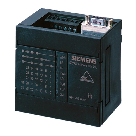
Siemens DP/AS-Interface Link 20E User manual

Siemens

Siemens DP/AS-Interface Link 20E User manual

Siemens SIMATIC NET CP 243-1 IT User manual

Siemens

Siemens SIMATIC NET CP 243-1 IT User manual

Siemens SMN42 User manual

Siemens

Siemens SMN42 User manual

Siemens SIMATIC CP 340 User manual

Siemens

Siemens SIMATIC CP 340 User manual

Siemens 6GK7343-1EX10-0XE0 User manual

Siemens

Siemens 6GK7343-1EX10-0XE0 User manual

Siemens SIMATIC NET CP 5614 A2 User manual

Siemens

Siemens SIMATIC NET CP 5614 A2 User manual

Siemens Simatic S7-300 Instruction manual

Siemens

Siemens Simatic S7-300 Instruction manual

Siemens SENTRON PROFIBUS DPV1 Series User manual

Siemens

Siemens SENTRON PROFIBUS DPV1 Series User manual

Siemens SINUMERIK 808D User manual

Siemens

Siemens SINUMERIK 808D User manual

Siemens TC65 User manual

Siemens

Siemens TC65 User manual

Siemens CP 5613 A3 User manual

Siemens

Siemens CP 5613 A3 User manual

Siemens SIMATIC S7-400 CP 440 User manual

Siemens

Siemens SIMATIC S7-400 CP 440 User manual

Popular Computer Hardware manuals by other brands

Panasonic 2SC2404 Specification sheet

Panasonic

Panasonic 2SC2404 Specification sheet

Asus AGP-V3100 user manual

Asus

Asus AGP-V3100 user manual

Spectrum Monaco Quad 'C6x VME64 Technical reference guide

Spectrum

Spectrum Monaco Quad 'C6x VME64 Technical reference guide

Cypress MB91460 manual

Cypress

Cypress MB91460 manual

Intel LGA1155 SOCKET - THERMAL MECHANICAL S AND DESIGN GUIDELINES... installation instructions

Intel

Intel LGA1155 SOCKET - THERMAL MECHANICAL S AND DESIGN GUIDELINES... installation instructions

Alphacool EISBAER AURORA manual

Alphacool

Alphacool EISBAER AURORA manual

Ceiec Electric PMC-1380-3 Series user manual

Ceiec Electric

Ceiec Electric PMC-1380-3 Series user manual

Softing CAN-AC 104 Series Hardware user manual

Softing

Softing CAN-AC 104 Series Hardware user manual

Nvidia ConnectX-7 user manual

Nvidia

Nvidia ConnectX-7 user manual

Wincor Nixdorf BEETLE operating manual

Wincor Nixdorf

Wincor Nixdorf BEETLE operating manual

TYAN FA100-B7118 manual

TYAN

TYAN FA100-B7118 manual

Alphacool Eisblock GPX manual

Alphacool

Alphacool Eisblock GPX manual

Mitsubishi GT 10-LDR user manual

Mitsubishi

Mitsubishi GT 10-LDR user manual

Noctua NM-i115x-1200 installation manual

Noctua

Noctua NM-i115x-1200 installation manual

Lexicon VORTEX - MANUAL 2 user guide

Lexicon

Lexicon VORTEX - MANUAL 2 user guide

Thermaltake TH240 ARGB Sync installation guide

Thermaltake

Thermaltake TH240 ARGB Sync installation guide

Analog Devices ADAU1961 manual

Analog Devices

Analog Devices ADAU1961 manual

AmbiCom WL54-CF user manual

AmbiCom

AmbiCom WL54-CF user manual

manuals.online logo
manuals.online logoBrands
  • About & Mission
  • Contact us
  • Privacy Policy
  • Terms and Conditions

Copyright 2025 Manuals.Online. All Rights Reserved.