manuals.online logo
Brands
  1. Home
  2. •
  3. Brands
  4. •
  5. Siemens
  6. •
  7. Controllers
  8. •
  9. Siemens N 605D41 User manual

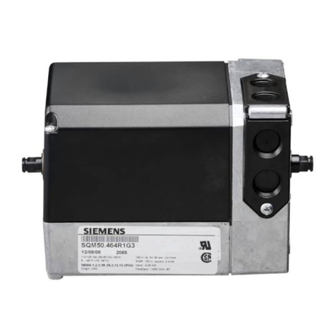
Siemens N 605D41 User manual

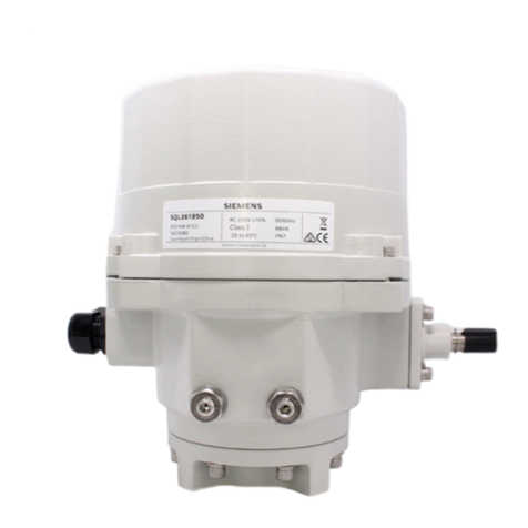
Thermal Drive Actuator N 605D41, 6 x AC 24...230 V
N 605D41
The thermal drive actuators are used for controlling electro-thermal actuators
for heating or cooling systems.
● 6 semiconductor outputs for noiseless control of AC 24 V or AC 230 V actuators
● Direct operation for efficient installation with switching status and control value dis-
play via LED.
● Error LEDs on the device front for indicating a mains voltage failure and overload/
short circuit faults
● Maintenance-free terminals for connecting and looping through solid, stranded and
fine-stranded conductors.
Functions for configuration with ETS:
● With priority control of security and override functions
● Automatic or demand-based or manual valve flushing
● Extensive, internal room temperature controllers and ventilation controllers (which
can be assigned freely or for each channel)
● Powerful calculator modules for weighting temperature values or determining the
largest or a weighted control value
● Interaction with primary systems for heating demand or cooling demand require-
ments and demand-based pump control.
A6V13488290_en--_a Smart Infrastructure
2023-02-07
2
Smart Infrastructure A6V13488290_en--_a
GAMMA Instabus 2023-02-07
Characteristics
The thermal drive actuator is used to control electro-thermal actuators in water-based heat-
ing or cooling systems. It is used in building automation. Device control is conducted via
KNX.
The thermal drive actuator features semiconductor outputs. These can be used to silently
control several AC 230 V or AC 24 V actuators per channel or channel group according to
their power consumption. When using Siemens STA/STP actuators, up to 6 (AC 230 V) or
up to 4 (AC 24 V) actuators can be controlled per channel.
The actuator controls both de-energized closed and de-energized open actuators.
In addition, the thermal drive actuator contains internal room temperature controllers match-
ing the number of valve outputs. These can be internally assigned directly to the valve out-
puts. The various control values of the controller are directly linked to the control value inputs
of the valve outputs without external bus communication. In the same way, the valve outputs
can receive their control values via communication objects from external room temperature
controllers, such as those integrated into sensors or room control units. On the other hand,
these room temperature controllers can be used as separate function blocks. In this case,
the various control values are linked via communication objects to external thermal drive ac-
tuators, motor actuators or fan coil actuators that do not include a controller function.
The thermal drive actuator has a direct operating level at the front of the device. A mem-
brane keypad with one operating key and one status LED per channel can be used to open
or close the control valves or display the valve positions/control values.
The thermal drive actuator detects a failure of the valve supply voltage and indicates the fail-
ure via simultaneous flashing (1Hz) of all error LEDs on the front of the device. This failure
is also sent via the bus.
The thermal drive actuator also detects and overload or short circuit on the valve outputs. To
do this, a diagnostic routine is executed. If a group of channel outputs exceeds a total cur-
rent, the affected error LEDs of that group light up on the front panel of the device. This over-
load is also sent via the bus. In the event of an overload/short-circuit fault on an individual
channel output, the affected fault LED on the front panel flashes (10 Hz), while the overload/
short-circuit fault is signaled to the respective channel via the bus at the same time.
The device is a rail-mounted device in N dimension for installation in distributions and install-
ation on 35-mm DIN rails as per standard IEC60715. The bus connection of the device uses
a bus terminal block. The electronics of the device are supplied via the bus voltage (no addi-
tional supply voltage required). The maintenance-free terminals are for connecting solid and
fine-stranded conductors with conductor cross-sections from 0.5 to 2.5mm² or for connect-
ing multi-stranded conductors with 2.5mm² conductor cross-sections to the output channels.
Stranded and fine-stranded conductors can be plugged into the terminals without ferrules.
The thermal drive actuator N 605D41 consists of the device (hardware) and the application
program (software).
Functions
Factory settings
In the factory settings, the functions control value transfer for a “switching control value (1
bit)" and a "continuous control value (8 bit)" are assigned to the building site function for all
channels (outputs). Direct operation is enabled.
Building site function
In the factory settings, the building site function enables transfer for a "switching control
value (1 bit)" and a "continuous control value (8 bit)" for controlling the thermal actuators via
a corresponding bus pushbutton, even if these devices are yet to be commissioned via the
Engineering Tool Software (ETS).
3
Smart Infrastructure A6V13488290_en--_a
GAMMA Instabus 2023-02-07
Programming mode
1
Fig.1: Programming button and programming LED (exemplary illustration)
After bus voltage recovery, wait several seconds before pushing the programming (1) but-
ton (not before booting is complete).
Activate programming mode
a) Briefly press the programming button (1) (< 2 seconds).
ðProgramming mode is activated.
ðThe programming LED (1) illuminates continuously.
Deactivating programming mode
üProgramming mode is activated. The programming LED (1) illuminates continuously.
a) Briefly press the programming button (1) (< 2 seconds).
ðProgramming mode is deactivated.
ðThe programming LED (1) is not illuminated.
Resetting the device to factory settings
NOTICE
Loss of data due to resetting device!
When you reset the device, all parameters and settings entered are deleted.
● Ensure that the device is really supposed to be reset.
A very long push of the programming button (1) of more than 20 seconds resets the device
to its factory settings. This is indicated by a uniform flashing of the programming LED for a
duration of 8 seconds.
All configuration settings are deleted. The building site function from the factory settings is
re-activated.
Behavior on unloading the application program
After unloading the application program with the ETS, the unloaded device has no functions.
Behavior on voltage failure/recovery
The electronics of the device are bus powered. A mains voltage failure therefore only leads
to a functional failure of the device if the bus voltage also fails as a result of the mains
voltage failure.
In case of a bus voltage failure, the current status and other values for each channel are
saved permanently so that they can be restored when the bus voltage is recovered.
When bus voltage is recovered, the configured actions for each channel are executed and,
depending on the parameters set, new statuses are reported.
For each active override, a starting behavior on bus voltage recovery can be configured (Off,
On, Deactivated, Last value).
Setting the valve control direction
De-energized closed or de-energized open thermal actuators can be connected to the
thermal drive actuator. The valve control direction is set to take this behavior into account in
the further electrical valve control.
4
Smart Infrastructure A6V13488290_en--_a
GAMMA Instabus 2023-02-07
Controlling the actuator channels
The actuator channels are controlled via switching commands On/Off (1-bit); the telegrams
are converted directly at the output Continuous positioning commands in percent (1 byte) are
converted into a switching control of the thermal actuators via pulse width modulation (PWM)
or via limit value evaluation (limit values for opening or closing the valve).
Control value monitoring
SchutzeinteilungIf positioning commands do not occur within a configurable time, emergency
operation with configurable default behavior is activated and an error status is sent. Different
continuous default control values (%) in normal operation can be set for summer and winter
mode
Control value limitation for continuous control value (1 byte)
The control value can be limited to maximum and minimum values (%) e.g. for basic temper-
ature control or to increase the service life of the thermal drives.
On the other hand, the valve can always be closed if the control value is smaller than a con-
figurable limit value or the valve can always be opened if the control value is larger than a
configurable limit value.Specific valve characteristics are thus taken into account.
Direct operation
The membrane keypad on the device front can be used to operate the actuators directly. A
status LED for each channel shows the status of the valve.
Direct operation enables the installer to test the installation and thermal actuators prior to
configuration with ETS. For each channel, a button can be used to open and close the valve.
The status LED shows if the valve is open or closed. The configured valve control direction is
taken into account here.
Mains voltage failure detection
The failure of the valve voltage supply is signaled directly by the simultaneous flashing (1
Hz) of all 6 error LEDs on the front of the device. A 1-bit message can be sent at the same
time.
Overload and short circuit detection
A diagnostic routine is performed to identify the overload. The diagnostic routine can also be
started manually on the relevant channel group A/B/C or D/E/F by means a long push of a
button (> 5 s). Alternatively, a diagnostic run by group can be started via a 1 bit command for
each group. In the diagnostic routine, the affected error LEDs of channel groups A/B/C and/
or D/E/F on the front of the device flash for approx. 60 s (3 Hz). At the same time, the execu-
tion of a diagnostic routine related to channels A/B/C and/or D/E/F can be sent as a 1-bit
message.
Group-related evaluation of channels A/B/C or D/E/F
If the total current exceeds ∑ I > Imax per group, all error LEDs of the affected channel groups
A/B/C or D/E/F light up on the front of the device. At the same time, the overload can be sent
as a 1-bit message in groups for channels A/B/C or D/E/F.
Excess current/short circuit evaluation per channel
In the event of an excess current/short circuit fault (I > Imax. ) on a single channel, the respect-
ive channel LED A, B, C, D, E or F flashes (10 Hz) on the front of the device. At the same
time, the respective overload for the affected channel can be sent as a 1-bit message.
5
Smart Infrastructure A6V13488290_en--_a
GAMMA Instabus 2023-02-07
Valve flushing
Valve flushing is used to protect against calcification and seizure of valves that are not used
for an extended period of time
Manual valve flushing
Start (for the set duration)/stop via a 1-bit object
Automatic valve flushing
Cyclically in weeks or demand-oriented if the control value remains below a limit value.
Valve flushing is reactivated at a control value of 0%.
Counting of operating hours
An operating hours counter can record the operating hours in hours or seconds at the valve
output using various evaluation methods.
On the one hand, the switch-on processes can be counted when electrical voltage is present
at the output, or the time for heating or cooling can be recorded, i.e. when the control value
exceeds an adjustable threshold value. When an adjustable threshold value is exceeded, a
message is sent via the bus.
Counting of switching cycles
Counting of switching cycles records the switching operations on the valve output. If an ad-
justable limit value is exceeded, a message is sent via the bus.
Overrides
The thermal drive actuator offers up to 6 override blocks per channel for specific applica-
tions. These can be used to configure settings for lock function, forced control, forced posi-
tion, service mode and user-defined settings. Their effectiveness can be individually set ac-
cording to priorities.
Room temperature control
The thermal drive actuator contains up to 6internal room temperature controllers as appro-
priate for the number of valve outputs. These can be used externally or internally assigned
directly to the valve outputs. The various control values of the controller are transferred dir-
ectly to the control value inputs of the valve outputs without external bus communication.
Only a single KNX bus device is used for valve control for single room temperature control.
In addition, the room temperature controllers can be used as separate, independent function
blocks in a KNX system. In this case, the various control values are linked via communica-
tion objects to external thermal drive actuators, motor actuators or fan coil actuators that do
not include a controller function.
Heating or cooling requirements
The heating or cooling requirements are used as a power saving function for a primary sys-
tem. For heating and cooling demand requirements, the assigned control values of the valve
outputs are evaluated. Based on the result, relevant switching inputs to burner and boiler
controls are switched according to demand via a KNX switching actuator.
Determination of the largest or a weighted control value
The largest or a weighted control value is determined via the internal calculator. The result
can be sent as a 1-byte control value directly to a primary system with integrated KNX inter-
face. The flow temperature can thus be adapted to the demand from the rooms.
Pump control
The pump control is used for demand-based control of circulating pumps as a power saving
function of a primary system. In the thermal drive actuator, there are two controls for circulat-
ing pumps with which a heating cycle and a cooling cycle can be controlled separately. In
doing so, the assigned control values of the valve outputs are evaluated. Based on the result
of the evaluation of the control values, the pumps can be switched based on demand via a
KNX switching actuator. In addition, separate fixed position protection prevents the pumps
from jamming if they have not been switched on for a longer period of time.
6
Smart Infrastructure A6V13488290_en--_a
GAMMA Instabus 2023-02-07
Logic operations
The thermal drive actuator has 6 independent logic blocks with which different mathematical
operations are possible: AND, OR, XOR, TRIGGER, LOCK.
The inputs can be linked internally in the device with the status output of the valve control
values of a channel or with any KNX communication objects, including external devices. The
logic result is sent via a KNX communication object. The data types of the logic inputs and
outputs can be selected freely.
Display/operating elements and error displays on the device.
On the front of the thermal drive actuator, the error LEDs indicate whether there is an error
on the device and what type of error it is. The buttons can be used to start the diagnostic
routine.
1
Fig.2: Error display on the device
1 Error LEDs: Error display of the channels and channel groups
Error messages
Mains voltage failure
The thermal drive actuator detects a failure of the common valve voltage supply. The failure
is indicated via the error LEDs on the front of the device.
The failure of the valve voltage supply can be reported via the bus.
Fig.3: Error display on mains voltage failure
Description
● Failure of the AC 24V or AC 230V valve supply voltage.
● All 6 error LEDs flash simultaneously with a frequency of 1Hz.
● The failure of the mains voltage is also reported via a 1-bit error message via the KNX
bus.
7
Smart Infrastructure A6V13488290_en--_a
GAMMA Instabus 2023-02-07
Diagnostic routine
Each channel or a channel group of the thermal drive actuator detects an overload or a short
circuit on the valve outputs. Here, a diagnostic routine is executed, which works group by
group for the channel outputs A/B/C or D/E/F and takes approx. 60s.
Fig.4: Display of the diagnostic routine
Description
● The affected error LEDs of channel groups A/B/C and/or D/E/F flash at a frequency of 3
Hz for approx. 60 s.
● The diagnostic routine starts after an overload has been detected.
There are three different ways in which a diagnostic routine can be started:
● Automatic start when a fault is detected (overload).
● Manual start using a long push of a button (> 5 s) on channel A, B or C to start the dia-
gnostic routine for channel group A/B/C or on channel D, E or F to start the diagnostic
routine for channel group D/E/F (Fig.: “,” 2).
● When sending a start telegram via the communication object (“Start diagnostic run chan-
nels A/B/C“ or “Start diagnostic run channels D/E/F“).
Short circuit/overload per channel
NOTICE
Damage to the device due to improper operation in the event of a permanent short
circuit on the channel or a channel group
The device can be damaged if the diagnostic routine is started repeatedly (via a telegram
or via the channel key) when a short circuit is permanently present.
● Before starting the diagnostic routine, the short circuit fault must be resolved.
In the event of an overload/short-circuit fault on a single channel output, the affected fault
LED on the front of the device flashes at a frequency of 10 Hz (fig. „,” 1).
The overload/short circuit error for the respective channel can be reported via the bus.
Fig.5: Error display for short circuit/overload per channel
Description
● The error LED of the affected channel flashes with a frequency of 10Hz (example
channel A).
8
Smart Infrastructure A6V13488290_en--_a
GAMMA Instabus 2023-02-07
Overload on the channel groups
In the event of a total current overflow of a group of channel outputs, the error LEDs of the
affected channel group on the front of the device light up continuously (fig. “,” 1).
The overload can be reported via the bus.
Fig.6: Error display for overload on the channel groups
Description
● The error LEDs of the affected channel groups A/B/C and/or D/E/F light up perman-
ently.
9
Smart Infrastructure A6V13488290_en--_a
GAMMA Instabus 2023-02-07
Schematic design of a thermal drive actuator channel
Control value
monitoring
Control value
monitoring
Override Control value limitation
PWM calculation
PWM calculation
Control value
temperature controller
Control value (1 bit)
Control value (8 bit)
Control value
monitoring
Send status values
Control value limitation
Override 1 – 6
1 bit
8 bit
Control value monitoring
Control value limitation
Override 1 – 6
Valve flushing
≥ 1 active
Overrides
status
Overrides 1 – 6
status
Control value limitation
Override
Valve flushing
Control value
Control value
Direct operation
Switching cycles
counting of operating hours
Switching cycles
counting of operating hours Direct operation
Direct operation lock
Direct operation
Status direct operation
Status
control value limitation
Status control value (1 bit)
Status control value (8 bit)
Status switching
Status number of switching cycles
Status operating hours
Error control value
PWM calculation
Valve flushing
Valve flushing
start/stop Valve flushing status
Number of
switching cycles
Operating hours
Switching cycles
Operating hours
10
Smart Infrastructure A6V13488290_en--_a
GAMMA Instabus 2023-02-07
Technical design
Position and function of the connections and labeling
1
2
3
4
5
Ɛ
Fig.7: Position and function of the connections and labeling, Thermal Drive Actuator N 605D41, 6 x AC
24...230 V
Pos. Element Function
1 Connection pins for KNX bus terminal
block, screwless
Connect KNX bus.
2 Label field Enter physical address.
3 Connection terminals Connect input and loads.
4 Labeling of the control outputs
5 Membrane keypad with LEDs Execute direct operation.
Open and close valve.
Display status, diagnostic routine and error messages.
11
Smart Infrastructure A6V13488290_en--_a
GAMMA Instabus 2023-02-07
Position and function of the operating and display elements
2
3
1
4
5
6
7
Fig.8: Operating and display elements, Thermal Drive Actuator N 605D41, 6 x AC 24...230 V
Pos. Operating or display element Function
1 Programming LED (red),
Programming button
Short push of button (<2s):
● Activate programming mode, display status (LED on = act-
ive).
Very long push of button (> 20s):
● Reset to factory settings (after 20s, the LED starts flashing
for about 8s).
2 Button: Deactivate direct operation Short push of the button:
● Deactivate direct operation for all channels.
Hold down the key and briefly press the "Open/close valve" key
of a channel (4):
● Deactivate the direct operation of the respective channel.
3 Status LED of direct operation (yellow) LED flashes if direct operation is active for at least one channel.
4 Button: Open/close valve of a channel Short push of button (< 5s):
● Open/close valve.
● Activate direct operation for the channel.
The "Open" or "Close" function is executed according to the
configuration of the valve control direction. In the factory
settings, the setting “Valve in de-energized state: Closed“ is
active.
Long push of the button of channel A, B or C (>5s):
● Start diagnostic routine for error detection for channel group
A/B/C.
Long push of the button of channel D, E or F (>5s):
● Start diagnostic routine for error detection for channel group
D/E/F.
12
Smart Infrastructure A6V13488290_en--_a
GAMMA Instabus 2023-02-07
Pos. Operating or display element Function
5 Status LED of a channel (red) Indicates the status of the respective channel.
Bus operation:
● 2-point controller/2-point operation:
– LED ON: Valve is opened under consideration of the
valve control direction.
– LED OFF: Valve is closed under consideration of the
valve control direction.
● PWM mode:
– LED ON: Control value 100%, valve is opened under
consideration of the valve control direction.
– LED OFF: Control value 0%, valve is closed under con-
sideration of the valve control direction.
– The LED flashes asymmetrically with a period duration
of approx. 5 sec. and thus maps the control value.
Example:
LED 0.5s ON, 4.5s OFF: Control value 10 %
LED 2.0s ON, 3.0s OFF: Control value 40 %
LED 3.5s ON, 1.5s OFF: Control value 70 %
LED 4.5s ON, 0.5s OFF: Control value 90 %
Direct operation:
● LED flashes alternately with the status LED for direct opera-
tion: Valve is opened under consideration of the valve con-
trol direction.
● LED flashes simultaneously to the status LED for direct op-
eration: Valve is closed under consideration of the valve
control direction.
6 Test contacts Metering point for voltage testing
7 Error LEDs Indicate the error detection status (Display/operating elements
and error displays on the device. [}6]).
13
Smart Infrastructure A6V13488290_en--_a
GAMMA Instabus 2023-02-07
Type overview
Type Description Item number KNX PL-Link
N 605D41 Thermal Drive Actuator N
605D41, 6 x AC 24...230
V
5WG1605-1DB41 yes
Version of the Engineering Tool Software
Application Version
Engineering Tool Software (ETS) ETS 5 or above
Accessories
Type Order number Description
5WG1118-4AB01 Automation module box AP 118
5WG1641-3AB01 Room automation module box AP
641
Table1: Automation module box AP 118 and room automation module box AP 641
Type Order number Operating voltage
STA 121 S55174-A177 AC/DC 24 V
STA 121.L20 S55174-A181 AC/DC 24 V
STA 121.L20H S55174-A195 AC/DC 24 V
STA 121.L50 S55174-A185 AC/DC 24 V
STA 321 S55174-A178 AC 230 V
STA 321.L20 S55174-A182 AC 230 V
STA 321.L20H S55174-A196 AC 230 V
STA 321.L50 S55174-A186 AC 230 V
Table2: Type overview STA..21..thermal actuators, NC in de-energized state
14
Smart Infrastructure A6V13488290_en--_a
GAMMA Instabus 2023-02-07
Type Order number Operating voltage
STP 121 S55174-A179 AC/DC 24 V
STP 121.L20 S55174-A183 AC/DC 24 V
STP 121.L50 S55174-A187 AC/DC 24 V
STP 321 S55174-A180 AC 230 V
STP 321.L20 S55174-A184 AC 230 V
STP 321.L50 S55174-A188 AC 230 V
Table3: Type overview STP..21.. thermal actuators, NO in de-energized state
Product documentation and support
Product documentation
Documents related the product, such as operating and installation instructions, application
program description, product database, additional software and CE declarations can be
downloaded from the following website:
http://www.siemens.com/gamma-td
Frequently asked questions
For frequently asked questions about the product and their solutions, see:
https://support.industry.siemens.com/cs/products?dtp=Faq&mfn=ps&lc=de-WW
FAQ
Support
Contact details for additional questions relating to the product:
Tel.: +49 89 9221-8000
http://www.siemens.com/supportrequest
15
Smart Infrastructure A6V13488290_en--_a
GAMMA Instabus 2023-02-07
Notes
Security
CAUTION
National safety regulations
Failure to comply with national safety regulations may result in personal injury and property
damage.
● Observe national provisions and comply with the appropriate safety regulations.
WARNING
Risk of death due to electric voltage and electric current!
Electrical expertise is required for the installation. Incorrect installation can deactivate elec-
trical safety features without this being apparent to a lay person.
● Do not open the casing of the device.
● The device should only be installed and put into operation by a certified electrician.
● Overload/short-circuit faults may only be rectified by qualified electricians and with the
AC voltage switched off.
● Secure each phase with a B16 line protection switch.
● Only use conventional transformers that comply with the relevant standards and con-
tain a thermal fuse.
WARNING
Danger due to electrical voltage
The device is not suitable for unlocking.
Voltage may be present at the outputs even when the device is switched off. When working
on the connected consumers, always disconnect the device from the power supply via the
upstream fuse.
NOTICE
Behavior in the event of a fault
wActuators of a channel output or a group do not switch.
● Identify the cause of the overload shutdown using the error LEDs on the front of the
device.
● Switch off the power supply.
● Resolve short circuit/overload and replace defective actuators.
● Check and, if appropriate, reduce the number of connected actuators.
● Switch on the power supply of the device again.
16
Smart Infrastructure A6V13488290_en--_a
GAMMA Instabus 2023-02-07
Start-up
Connecting thermal actuators to the semiconductor outputs
Fig.9: Thermal Drive Actuator N 605D41, 6 x AC 24...230 V
Cu
0.5...2.5 mm²
2.5 mm²
17
Smart Infrastructure A6V13488290_en--_a
GAMMA Instabus 2023-02-07
Connecting KNX
Fig.10: Thermal Drive Actuator N 605D41, 6 x AC 24...230 V
Cu
0.6…0.8mm
Testing KNX 24 V DC type. SELV
This test can be used to check whether the bus connection cable is connected with the cor-
rect polarity and whether device is supplied with bus voltage.
Fig.11: Thermal Drive Actuator N 605D41, 6 x AC 24...230 V
A very long push of the programming button of more than 20 seconds resets the device to its
factory settings.
18
Smart Infrastructure A6V13488290_en--_a
GAMMA Instabus 2023-02-07
Status display in bus operation (A|B|C|D|E|F Un~24...230 V)
Fig.12: Thermal Drive Actuator N 605D41, 6 x AC 24...230 V
For pulse width modulation (PWM), the flashing of the status LED represents the control of
the output. The period duration is 5s fixed.
Function test of the installation
This test can be used to check whether the thermal actuators have been connected cor-
rectly.
Fig.13: Thermal Drive Actuator N 605D41, 6 x AC 24...230 V
Disposal
The device is considered an electronic device for disposal in accordance
with European Directive and may not be disposed of as domestic waste.
● Use only designated channels for disposing the devices.
● Comply with all local and currently applicable laws and regulations.
If a device is defective, contact the local sales office.
19
Smart Infrastructure A6V13488290_en--_a
GAMMA Instabus 2023-02-07
Technical data
Power supply
KNX bus voltage DC 24 V (DC 21...30 V)
KNX power consumption 15 mA
KNX power loss (power consumption) 0.36 W
Outputs (semiconductor switch)
Number of outputs 6
Switching voltage AC 24V ... 230V (50 - 60 Hz)
Output current
Rated current per channel*10.5 A
max. inrush current (2 s)*13.5 A
max. inrush current (2 min)*10.9 A
Actuators
Number of actuators per channel or group
24 V
4*2
Number of actuators per channel or group
230 V
6*2
*1 per channel and group of 3 outputs
*2 in relation to Siemens STA/STP types - see Accessories [}13]
Power loss
Maximum power loss of the device at rated
output
2.1 W
Mechanical data
Housing material Plastic
Dimensions Rail-mounted device in N dimension, width 4
HP (1 HP = 18 mm)
Refer to Dimensions [}21].
Product weight 145 g
Fire load 4 MJ
Environmental conditions
Ambient temperature in operation -5 °C...+45 °C (23 °F...113 °F)
Storage temperature -20 °C...+70 °C (-4 °F...158 °F)
Transport temperature -25 °C...+70 °C (-13 °F...158 °F)
Relative humidity
(non-condensing)
5 %...95 %
Environmental rating EN 60721-3-3 class 3k5
Protection settings
Degree of pollution (according to IEC
60664-1)
2
Overvoltage category
(according to IEC 60664-1)
III
20
Smart Infrastructure A6V13488290_en--_a
GAMMA Instabus 2023-02-07
Protection settings
Housing protection class (according to EN
60529)
IP20
Electrical safety, bus (SELV) yes
Electrical safety, device fulfills EN 50428
EMC requirements, device complies with EN 50428
Test mark KNX, EAC, RCM, WEEE, China-RoHS
CE mark yes
Reliability
Failure rate (at 40°C) 471 fit
Connection example
Fig.14: Thermal Drive Actuator N 605D41, 6 x AC 24...230 V
CAUTION
A common supply voltage for all channels is applied to terminals L1 and N.
Two output channels share a central ground terminal.
The neutral conductors of the actuators can be connected either directly to the ground ter-
minal on the device or alternatively together via a suitable ground potential.
The neutral conductors of the outputs may only be used for connecting the electro-thermal
actuators.

Other Siemens Controllers manuals

Siemens RWD68U Owner's manual

Siemens

Siemens RWD68U Owner's manual

Siemens CP 1612 A2 User manual

Siemens

Siemens CP 1612 A2 User manual

Siemens Flowrite 599 Series Owner's manual

Siemens

Siemens Flowrite 599 Series Owner's manual

Siemens SIMOTION P320-4 E User manual

Siemens

Siemens SIMOTION P320-4 E User manual

Siemens acvatix SKD32 Series User manual

Siemens

Siemens acvatix SKD32 Series User manual

Siemens SIMOTION Series User manual

Siemens

Siemens SIMOTION Series User manual

Siemens SIPART DR21 User manual

Siemens

Siemens SIPART DR21 User manual

Siemens SIMATIC PN/BACnet LINK User manual

Siemens

Siemens SIMATIC PN/BACnet LINK User manual

Siemens SINUMERIK 802D sl Owner's manual

Siemens

Siemens SINUMERIK 802D sl Owner's manual

Siemens REV23.03RF User manual

Siemens

Siemens REV23.03RF User manual

Siemens SQN72 Series User manual

Siemens

Siemens SQN72 Series User manual

Siemens RC 195 User manual

Siemens

Siemens RC 195 User manual

Siemens SINAMICS G130 User manual

Siemens

Siemens SINAMICS G130 User manual

Siemens IP Control Center N152 User manual

Siemens

Siemens IP Control Center N152 User manual

Siemens SSA911.01TH User manual

Siemens

Siemens SSA911.01TH User manual

Siemens RWD44U User guide

Siemens

Siemens RWD44U User guide

Siemens PolyCool CPS 40 User manual

Siemens

Siemens PolyCool CPS 40 User manual

Siemens RVA47.320 User manual

Siemens

Siemens RVA47.320 User manual

Siemens SINUMERIK 840D sl User manual

Siemens

Siemens SINUMERIK 840D sl User manual

Siemens 3RK1304-5 S70 Series User manual

Siemens

Siemens 3RK1304-5 S70 Series User manual

Siemens SQM5 Series Owner's manual

Siemens

Siemens SQM5 Series Owner's manual

Siemens SQD Series User manual

Siemens

Siemens SQD Series User manual

Siemens SIMATIC NET MOBIC T8 User manual

Siemens

Siemens SIMATIC NET MOBIC T8 User manual

Siemens Simatic S7-1500 User guide

Siemens

Siemens Simatic S7-1500 User guide

Popular Controllers manuals by other brands

Speedaire 4ZK78A Operating instructions & parts manual

Speedaire

Speedaire 4ZK78A Operating instructions & parts manual

Danfoss VLT Soft Starter MCD 600 installation guide

Danfoss

Danfoss VLT Soft Starter MCD 600 installation guide

VNS GeoBox G406L user guide

VNS

VNS GeoBox G406L user guide

TJERNLUND MAC1E CONTROL (COMPATIBLE WITH UC1 CONTROL) 8504110 REV A... Operating and mounting instructions

TJERNLUND

TJERNLUND MAC1E CONTROL (COMPATIBLE WITH UC1 CONTROL) 8504110 REV A... Operating and mounting instructions

Klimor HMI Compact Operation and maintenance manual

Klimor

Klimor HMI Compact Operation and maintenance manual

Absen AiBox3.1 user manual

Absen

Absen AiBox3.1 user manual

Victron energy BlueSolar MPPT 150/60-MC4 manual

Victron energy

Victron energy BlueSolar MPPT 150/60-MC4 manual

Tradinco 8810 user manual

Tradinco

Tradinco 8810 user manual

ACS Tech80 SB1391 manual

ACS Tech80

ACS Tech80 SB1391 manual

Vacon NX installation manual

Vacon

Vacon NX installation manual

TOHO TTM-210 Series user manual

TOHO

TOHO TTM-210 Series user manual

Ezodo 4801P manual

Ezodo

Ezodo 4801P manual

Ubiquiti UA-Hub quick start guide

Ubiquiti

Ubiquiti UA-Hub quick start guide

Krüger & Matz KM0771 owner's manual

Krüger & Matz

Krüger & Matz KM0771 owner's manual

Compit SOLARCOMP 911 Installation and operating instructions

Compit

Compit SOLARCOMP 911 Installation and operating instructions

PRECISION DIGITAL NOVA PD570 Series instruction manual

PRECISION DIGITAL

PRECISION DIGITAL NOVA PD570 Series instruction manual

Satel ACU-120 manual

Satel

Satel ACU-120 manual

Griffin Technology PowerMate quick start guide

Griffin Technology

Griffin Technology PowerMate quick start guide

manuals.online logo
manuals.online logoBrands
  • About & Mission
  • Contact us
  • Privacy Policy
  • Terms and Conditions

Copyright 2025 Manuals.Online. All Rights Reserved.