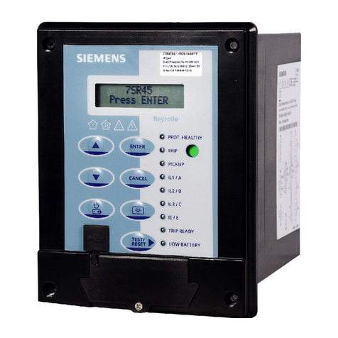
Front Panel Description:
1
Process-value (PV) /
Parameter name
display
1) Displaysaprocessvalue (PV).
2) Displays the parameter symbols
at configuration mode/online menu.
3) Displays PV error conditions.
(refer Table2)
5Tune
6Dwell timer
Auto tune :Blinking (Withfasterrate)
Self tune:Blinking (With slowerrate)
Blinking:Dwell timer is in progress.
Continuous ON :Timeover.
3Control output 1
indication
2Parametersetting
display
The LED is lit when the control
output1isON
Displays the parameter settings at
configuration mode/online menu.
4Control output 2
indication
The LED is lit when the control
output2isON
User Guide
1. Display Bias: This function is used to adjust the PV value in cases where it is necessary for PV value to agree with another recorder or indicator, or
when the sensor cannot be mounted in correct location.
2. Filter Time Constant: The input lter is used to lter out quick changes that occur to the process variable in a dynamic or quick responding
application which causes erratic control. The digital lter also aids in controlling processes where the electrical noise affect the input signal. Larger
the value of FTC entered, greater the lter added and slower the controller reacts to the process and vice-versa.
3. Manual Reset (for PID control & I= = 0): After sometime the process temperature settles at some
point and there is a difference between the set temperature and the controlled temperature. This
difference can be removed by setting the manual reset value equal and opposite to the offset.
4. Dwell Timer: A dwell timer is used to control a process at a xed temperature for a dened
period. Once the process reaches the setpoint, dwell timer starts to count from zero until time
out. After the time is completed, control output goes OFF and auxiliary output energies as an
alarm.
5. Auto tuning (AT): The Auto-tuning function automatically computes and sets the proportional
band (P), integral time (I), Derivative time (D), ARW% and cycle time (CYC.T) as per process
characteristics.
- While Auto-tune is in progress, ‘T’ LED will blink at a faster speed.
- After Auto-tuning is completed, the ‘T’ LED stops blinking
- If the power goes OFF before auto-tuning is completed, auto-tuning
will be restarted at next power ON.
- If auto-tuning is not completed after 3-4 cycles, it is suspected to fail.
In this case, check the wiring & parameters such as the control action,
input type, etc.
- Carry out the auto-tuning again, if there is a change in setpoint or
process parameters.
6. ON/OFF control action (For Reverse Mode): The relay is ‘ON’ up to the set temperature and cuts
‘OFF’ above the set temperature. As the temperature of the system drops, the relay is switched
‘ON’ at a temperature slightly lower than the set point.
HYSTERESIS: The difference between the temperature at which relay switches ‘ON’ and at which
the relay switches ‘OFF’ is the hysteresis or dead band.
7. Self tune (ST): It is used where modication of PID parameters is required repeatedly due to
frequent change in process condition eg. Setpoint
- When Self-tuning is in progress, ‘T’ LED blinks at slower rate
- At the completion of self-tuning, ‘T’ LED stop blinking.
- Self tuning is initiated under the following conditions:
a. When setpoint is altered.
b. When tune mode is altered (TUNE = ST)
- ST will start only if PV < 50% of setpoint.
- ST will work only when ACT = RE.
Auto tuning (AT)
Self tune (ST)
Auto tuning (AT)ON/OFF Control action
