ABB Relion 620 Series User manual

—
RELION® PROTECTION AND CONTROL
620 series ANSI
Operation Manual


Document ID: 1MAC456939-IB
Issued: 2019-05-29
Revision: D
Product version: 2.0 and 2.1
© Copyright 2019 ABB. All rights reserved

Copyright
This document and parts thereof must not be reproduced or copied without written
permission from ABB, and the contents thereof must not be imparted to a third party, nor
used for any unauthorized purpose.
The software or hardware described in this document is furnished under a license and may
be used, copied, or disclosed only in accordance with the terms of such license.
Trademarks
ABB and Relion are registered trademarks of the ABB Group. All other brand or product
names mentioned in this document may be trademarks or registered trademarks of their
respective holders.
Warranty
Please inquire about the terms of warranty from your nearest ABB representative.
www.abb.com/substationautomation

Disclaimer
The data, examples and diagrams in this manual are included solely for the concept or
product description and are not to be deemed as a statement of guaranteed properties. All
persons responsible for applying the equipment addressed in this manual must satisfy
themselves that each intended application is suitable and acceptable, including that any
applicable safety or other operational requirements are complied with. In particular, any
risks in applications where a system failure and/or product failure would create a risk for
harm to property or persons (including but not limited to personal injuries or death) shall
be the sole responsibility of the person or entity applying the equipment, and those so
responsible are hereby requested to ensure that all measures are taken to exclude or
mitigate such risks.
This product has been designed to be connected and communicate data and information
via a network interface which should be connected to a secure network. It is the sole
responsibility of the person or entity responsible for network administration to ensure a
secure connection to the network and to take the necessary measures (such as, but not
limited to, installation of firewalls, application of authentication measures, encryption of
data, installation of anti virus programs, etc.) to protect the product and the network, its
system and interface included, against any kind of security breaches, unauthorized access,
interference, intrusion, leakage and/or theft of data or information. ABB is not liable for
any such damages and/or losses.
This document has been carefully checked by ABB but deviations cannot be completely
ruled out. In case any errors are detected, the reader is kindly requested to notify the
manufacturer. Other than under explicit contractual commitments, in no event shall ABB
be responsible or liable for any loss or damage resulting from the use of this manual or the
application of the equipment.

Conformity
This product complies with the directive of the Council of the European Communities on
the approximation of the laws of the Member States relating to electromagnetic
compatibility (EMC Directive 2014/30/EU) and concerning electrical equipment for use
within specified voltage limits (Low-voltage directive 2014/35/EU). This conformity is
the result of tests conducted by ABB in accordance with the product standards EN 50263
and EN 60255-26 for the EMC directive, and with the product standards EN 60255-1 and
EN 60255-27 for the low voltage directive. The product is designed in accordance with the
international standards of the IEC 60255 series and ANSI C37.90. This product complies
with the UL 508 certification.

Safety information
Dangerous voltages can occur on the connectors, even though the
auxiliary voltage has been disconnected.
Non-observance can result in death, personal injury or substantial
property damage.
Only a competent electrician is allowed to carry out the electrical
installation.
National and local electrical safety regulations must always be followed.
The frame of the protection relay has to be carefully grounded.
When the plug-in unit has been detached from the case, do not touch the
inside of the case. The relay case internals may contain high voltage
potential and touching these may cause personal injury.
The protection relay contains components which are sensitive to
electrostatic discharge. Unnecessary touching of electronic components
must therefore be avoided.
Whenever changes are made in the protection relay, measures should be
taken to avoid inadvertent tripping.


Table of contents
Section 1 Introduction............................................................................7
This manual.............................................................................................. 7
Intended audience.................................................................................... 7
Product documentation.............................................................................8
Product documentation set..................................................................8
Document revision history................................................................... 8
Related documentation........................................................................9
Symbols and conventions.........................................................................9
Symbols...............................................................................................9
Document conventions...................................................................... 10
Functions, codes and symbols.......................................................... 10
Section 2 Environmental aspects........................................................ 17
Sustainable development....................................................................... 17
Disposal of a protection relay................................................................. 17
Section 3 620 series overview.............................................................19
Overview.................................................................................................19
Local HMI................................................................................................19
Display...............................................................................................20
LEDs..................................................................................................22
Keypad.............................................................................................. 22
Programmable push buttons with LEDs............................................ 25
Local HMI functionality...................................................................... 26
Protection and alarm indication.................................................... 26
Parameter management ..............................................................28
Front communication.................................................................... 28
Web HMI.................................................................................................29
Command buttons............................................................................. 30
Authorization...........................................................................................31
Audit trail............................................................................................31
Communication.......................................................................................34
Self-healing Ethernet ring.................................................................. 35
Ethernet redundancy......................................................................... 36
PCM600 tool........................................................................................... 38
Connectivity packages.......................................................................39
Table of contents
620 series ANSI 1
Operation Manual

PCM600 and relay connectivity package version..............................39
Section 4 Using the HMI......................................................................41
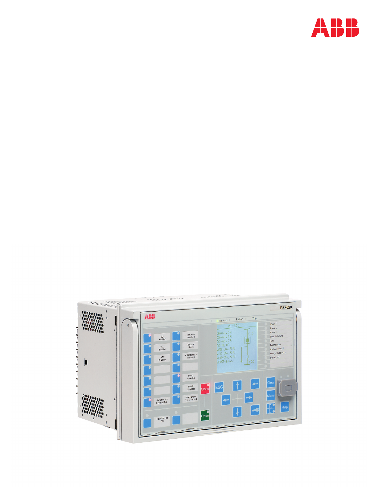
Using the local HMI.................................................................................41
Logging in.......................................................................................... 41
Logging out........................................................................................42
Turning the display backlight on........................................................ 43
Selecting local or remote use............................................................ 43
Identifying the device.........................................................................44
Adjusting the display contrast............................................................45
Changing the local HMI language..................................................... 46
Changing display symbols.................................................................46
Navigating in the menu......................................................................47
Menu structure..............................................................................47
Scrolling the display......................................................................47
Changing the default view............................................................ 48
Viewing single-line diagram...............................................................48
Changing single-line diagram symbol formats..............................49
Browsing setting values.....................................................................50
Editing values.................................................................................... 51
Editing numerical values...............................................................51
Editing string values..................................................................... 53
Editing enumerated values........................................................... 53
Committing settings........................................................................... 53
Clearing and acknowledging............................................................. 54
Using the local HMI help....................................................................55
Using the Web HMI.................................................................................55
Logging in.......................................................................................... 56
Logging out........................................................................................56
Identifying device...............................................................................57
Navigating in menus.......................................................................... 58
Menu structure..............................................................................59
Selecting single-line diagram.............................................................59
Showing parameters..........................................................................60
Editing values.................................................................................... 61
Committing settings........................................................................... 63
Clearing and acknowledging............................................................. 65
Selecting programmable LEDs view..................................................66
Selecting event view..........................................................................66
Selecting DFR records view.............................................................. 67
Table of contents
2620 series ANSI
Operation Manual

Uploading DFR records................................................................ 68
Triggering DFR recorder manually............................................... 69
Deleting DFR records................................................................... 70
Selecting phasor diagrams................................................................ 71
Selecting fault records....................................................................... 74
Using Web HMI help..........................................................................75
Section 5 Protection relay operation................................................... 77
Normal operation.................................................................................... 77
Disturbance identification........................................................................77
DFR recording triggering................................................................... 78
DFR record analysis.......................................................................... 78
DFR reports....................................................................................... 78
Relay self-supervision....................................................................... 79
Relay parametrization.............................................................................79
Settings for relay functionality............................................................79
Settings for different operating conditions......................................... 80
Section 6 Operating procedures..........................................................81
Monitoring............................................................................................... 81
Indications......................................................................................... 81
Monitoring indication messages................................................... 81
Monitoring an internal relay fault ................................................. 82
Monitoring condition monitoring data............................................82
Measured and calculated values....................................................... 82
Measured values.......................................................................... 82
Using the local HMI for monitoring............................................... 85
Recorded data................................................................................... 85
Creating digital fault records.........................................................85
Monitoring DFR data.................................................................... 86
Controlling and uploading of DFR recorder data.......................... 87
Monitoring fault records................................................................ 87
Monitoring events......................................................................... 88
Monitoring and uploading load profile record............................... 89
Remote monitoring............................................................................ 89
Monitoring protection relays remotely...........................................89
Controlling...............................................................................................89
Controlling with single-line diagram...................................................89
Controlling circuit breaker, disconnectors and earthing switch.....89
Controlling SLD buttons................................................................90
Controlling via the control menu........................................................ 91
Table of contents
620 series ANSI 3
Operation Manual

Resetting protection relays..................................................................... 93
Clearing and acknowledging via the local HMI..................................93
Changing the protection relay functionality.............................................94
Defining the setting group..................................................................94
Activating a setting group............................................................. 94
Copying a setting group................................................................95
Browsing and editing setting group values................................... 96
Activating programmable LEDs......................................................... 98
Setting autoscroll delay..................................................................... 98
Section 7 Troubleshooting ................................................................101
Fault tracing.......................................................................................... 101
Identifying hardware errors..............................................................101
Identifying runtime errors.................................................................101
Identifying communication errors.....................................................101
Checking front communication link operation.............................102
Checking time synchronization...................................................102
Running the display test.................................................................. 102
Indication messages............................................................................. 102
Internal faults................................................................................... 102
Warnings..........................................................................................105
Correction procedures.......................................................................... 107
Rebooting the software....................................................................107
Restoring factory settings................................................................ 107
Setting passwords........................................................................... 108
Identifying relay application problems............................................. 108
Inspecting wiring.........................................................................109
Sample data interruptions...........................................................109
Section 8 Commissioning..................................................................111
Commissioning checklist...................................................................... 111
Checking the installation.......................................................................112
Checking of the power supply......................................................... 112
Checking CT circuits........................................................................112
Checking VT circuits........................................................................113
Checking binary input and output circuits........................................113
Checking binary input circuits.....................................................113
Checking binary output circuits...................................................114
Checking optical connections.......................................................... 114
Authorizations....................................................................................... 114
User authorization........................................................................... 114
Table of contents
4620 series ANSI
Operation Manual

Using PCM600......................................................................................115
Setting the communication between protection relays and PCM600115
Communication link options between PCM600 and protection
relays.......................................................................................... 116
Setting communication parameters............................................ 116
Setting protection relay and communication.........................................121
Communication settings.................................................................. 121
Serial communication ports and drivers..................................... 122
Serial link diagnostics and monitoring........................................ 123
Defining Ethernet port settings................................................... 126
Defining serial port settings........................................................ 126
Setting communication protocol parameters.............................. 126
Connecting jumper connectors...................................................127
Communication checklist............................................................127
Setting the local HMI....................................................................... 128
Changing the local HMI language.............................................. 128
Adjusting the display contrast.....................................................128
Changing display symbols..........................................................129
Changing the default view.......................................................... 129
Setting the system time and time synchronization..................... 129
Setting protection relay parameters.................................................131
Defining setting groups...............................................................131
Relay parametrization.................................................................134
Defining DFR channel settings................................................... 135
Configuring analog inputs...........................................................135
Testing protection relay operation........................................................ 135
Selecting the test mode................................................................... 136
Testing the digital I/O interface........................................................136
Testing functions............................................................................. 137
Selecting the internal fault test........................................................ 137
ABB Product Data Registration............................................................ 138
Section 9 Glossary............................................................................ 139
Table of contents
620 series ANSI 5
Operation Manual

6

Section 1 Introduction
1.1 This manual
The operation manual contains instructions on how to operate the protection relay once it
has been commissioned. The manual provides instructions for monitoring, controlling
and setting the relay. The manual also describes how to identify disturbances and how to
view calculated and measured power grid data to determine the cause of a fault.
1.2 Intended audience
This manual addresses the operator who operates the protection relay frequently.
The operator must be trained in and have a basic knowledge of how to operate protection
equipment. The manual contains terms and expressions commonly used to describe this
kind of equipment.
1MAC456939-IB D Section 1
Introduction
620 series ANSI 7
Operation Manual

1.3 Product documentation
1.3.1 Product documentation set
Planning &
purchase
Engineering
Installation
Commissioning
Operation
Maintenance
Decommissioning,
deinstallation & disposal
Quick start guide
Quick installation guide
Brochure
Product guide
Operation manual
Installation manual
Connection diagram
Engineering manual
Technical manual
Application manual
Communication protocol manual
IEC 61850 engineering guide
Point list manual
Cyber security deployment guideline
GUID-06ED1128-B7CA-43DC-83B2-24A31B78D460 V1 EN
Figure 1: The intended use of documents during the product life cycle
Product series- and product-specific manuals can be downloaded from the
ABB Web site http://www.abb.com/relion.
1.3.2 Document revision history
Document revision/date Product series version History
A/2012-10-31 2.0 First release
B/2015-11-25 2.1 Content updated with release of REM620
Ver.2.1
C/2019-05-17 2.0 and 2.1 Content updated
D/2019-05-29 2.0 and 2.1 Content updated
Section 1 1MAC456939-IB D
Introduction
8620 series ANSI
Operation Manual

Download the latest documents from the ABB Web site
http://www.abb.com/substationautomation.
1.3.3 Related documentation
Product series- and product-specific manuals can be downloaded from the ABB Web site
http://www.abb.com/substationautomation.
1.4 Symbols and conventions
1.4.1 Symbols
The electrical warning icon indicates the presence of a hazard which could
result in electrical shock.
The warning icon indicates the presence of a hazard which could result in
personal injury.
The caution icon indicates important information or warning related to the
concept discussed in the text. It might indicate the presence of a hazard
which could result in corruption of software or damage to equipment or
property.
The information icon alerts the reader of important facts and conditions.
The tip icon indicates advice on, for example, how to design your project
or how to use a certain function.
Although warning hazards are related to personal injury, it is necessary to understand that
under certain operational conditions, operation of damaged equipment may result in
degraded process performance leading to personal injury or death. Therefore, comply
fully with all warning and caution notices.
1MAC456939-IB D Section 1
Introduction
620 series ANSI 9
Operation Manual

1.4.2 Document conventions
A particular convention may not be used in this manual.
• Abbreviations and acronyms are spelled out in the glossary. The glossary also
contains definitions of important terms.
• Push button navigation in the LHMI menu structure is presented by using the push
button icons.
To navigate between the options, use and .
• Menu paths are presented in bold.
Select Main menu/Settings.
• WHMI menu names are presented in bold.
Click Information in the WHMI menu structure.
• LHMI messages are shown in Courier font.
To save the changes in nonvolatile memory, select Yes and press .
• Parameter names are shown in italics.
The function can be enabled and disabled with the Operation setting.
• Parameter values are indicated with quotation marks.
The corresponding parameter values are "Enabled" and "Disabled".
• Input/output messages and monitored data names are shown in Courier font.
When the function picks up, the PICKUP output is set to TRUE.
• Dimensions are provided both in inches and mm. If it is not specifically mentioned,
the dimension is in mm.
1.4.3 Functions, codes and symbols
All available functions are listed in the table. All of them may not be applicable to all
products.
Table 1: Functions included in the relays
Function IEC 61850 IEC 60617 ANSI/C37.2 -2008
REF620 REM620 RET620
Protection
Three-phase non-directional overcurrent protection, low stage, instance
1PHLPTOC1 3I> (1) 51P 51P 51P (1)
Three-phase non-directional overcurrent protection, low stage, instance
2PHLPTOC2 3I> (2) 51P (2)
Three-phase non-directional overcurrent protection, low stage, instance
3PHLPTOC3 3I> (3) 51P (3)
Three-phase non-directional overcurrent protection, high stage,
instance 1 PHHPTOC1 3I>> (1) 50P-1 50P-11) 50P-1 (1)
Three-phase non-directional overcurrent protection, high stage,
instance 2 PHHPTOC2 3I>> (2) 50P-2 50P-22) 50P-2 (1)
Three-phase non-directional overcurrent protection, high stage,
instance 3 PHHPTOC3 3I>> (3) 50P-1 (2)
Table continues on next page
Section 1 1MAC456939-IB D
Introduction
10 620 series ANSI
Operation Manual

Function IEC 61850 IEC 60617 ANSI/C37.2 -2008
REF620 REM620 RET620
Three-phase non-directional overcurrent protection, high stage,
instance 4 PHHPTOC4 3I>> (4) 50P-2 (2)
Three-phase non-directional overcurrent protection, high stage,
instance 5 PHHPTOC5 3I>> (5) 50P-1 (3)
Three-phase non-directional overcurrent protection, high stage,
instance 6 PHHPTOC6 3I>> (6) 50P-2 (3)
Three-phase non-directional overcurrent protection, instantaneous
stage, instance 1 PHIPTOC1 3I>>> (1) 50P-3
Three-phase non-directional long time overcurrent protection, lower
stage, instance 1 PHLTPTOC1 3I> (3) 51LT
Three-phase directional overcurrent protection, low stage, instance 1 DPHLPDOC1 3I> -> (1) 67/51P 67/51P(1)
Three-phase directional overcurrent protection, low stage, instance 2 DPHLPDOC2 3I> -> (2) 67/51P(2)
Three-phase directional overcurrent protection, high stage, instance 1 DPHHPDOC1 3I>> -> (1) 67/50P-1
Three-phase directional overcurrent protection, high stage, instance 2 DPHHPDOC2 3I>> -> (2) 67/50P-2
Non-directional earth-fault protection, low stage, instance 1 EFLPTOC1 Io> (1) 51G 51G 51G
Non-directional earth-fault protection, low stage, instance 2 EFLPTOC2 Io> (2) 51N-1 51N (1)
Non-directional earth-fault protection, low stage, instance 3 EFLPTOC3 Io> (3) 51N (2)
Non-directional earth-fault protection, low stage, instance 4 EFLPTOC4 Io> (4) 50SEF 51N (3)
Non-directional earth-fault protection, high stage, instance 1 EFHPTOC1 Io>> (1) 50G-1 50G-11) 50G
Non-directional earth-fault protection, high stage, instance 2 EFHPTOC2 Io>> (2) 50G-2 50G-22)
Non-directional earth-fault protection, high stage, instance 3 EFHPTOC3 Io>> (3) 50N-1 50N-1 (1)
Non-directional earth-fault protection, high stage, instance 4 EFHPTOC4 Io>> (4) 50N-2 50N-1 (2)
Non-directional earth-fault protection, high stage, instance 5 EFHPTOC5 Io>> (5) 50N-1 (3)
Non-directional earth-fault protection, instantaneous stage, instance 1 EFIPTOC1 Io>>>(1) 50G-3
Non-directional earth-fault protection, instantaneous stage, instance 2 EFIPTOC2 Io>>>(2) 50N-3
Directional earth-fault protection, low stage, instance 1 DEFLPDEF1 Io> -> (1) 67/51N 67/51N 67/51N(1)
Directional earth-fault protection, low stage, instance 2 DEFLPDEF2 Io> -> (2) 67/51N(2)
Directional earth-fault protection, high stage, instance 1 DEFHPDEF1 Io>> -> (1) 67/50N-1
Directional earth-fault protection, high stage, instance 2 DEFHPDEF2 Io>> -> (2) 67/50N-2
Three-phase directional power protection, instance 1 DPSRDIR1 I1-> (1) 32P-1 32P(1)
Three-phase directional power protection, instance 2 DPSRDIR2 I1-> (2) 32P(2)
Ground directional power protection, instance 1 DNZSRDIR1 I2 ->, Io-> (1) 32N-1 32N(1)
Ground directional power protection, instance 2 DNZSRDIR2 I2 ->, Io-> (2) 32N(2)
Phase distance protection, instance 1 PHDSTPDIS1 Z< 21P 21P3)
Negative-sequence overcurrent protection, instance 1 NSPTOC1 I2> (1) 46-1 46 (1)
Negative-sequence overcurrent protection, instance 2 NSPTOC2 I2> (2) 46-2 46 (2)
Negative-sequence overcurrent protection, instance 3 NSPTOC3 I2> (3) 46 (3)
Phase discontinuity protection PDNSPTOC1 I2/I1> 46PD
Residual overvoltage protection, instance 1 ROVPTOV1 Uo> (1) 59G 59G 59G
Residual overvoltage protection, instance 2 ROVPTOV2 Uo> (2) 59N-1 (1) 59N 59N(1)
Residual overvoltage protection, instance 3 ROVPTOV3 Uo> (3) 59N-1 (2) 59N(2)
Three-phase undervoltage protection, instance 1 PHPTUV1 3U< (1) 27-1 (1) 27-11) 27-1 (1)
Three-phase undervoltage protection, instance 2 PHPTUV2 3U< (2) 27-2 (1) 27-22) 27-2 (1)
Three-phase undervoltage protection, instance 3 PHPTUV3 3U< (3) 27-1 (2) 27-1 (2)
Three-phase undervoltage protection, instance 4 PHPTUV4 3U< (4) 27-2 (2) 27-2 (2)
Three-phase overvoltage protection, instance 1 PHPTOV1 3U> (1) 59-1 (1) 59-11) 59-1 (1)
Three-phase overvoltage protection, instance 2 PHPTOV2 3U> (2) 59-2 (1) 59-22) 59-2 (1)
Three-phase overvoltage protection, instance 3 PHPTOV3 3U> (3) 59-1 (2) 59-1 (2)
Table continues on next page
1MAC456939-IB D Section 1
Introduction
620 series ANSI 11
Operation Manual

Function IEC 61850 IEC 60617 ANSI/C37.2 -2008
REF620 REM620 RET620
Three-phase overvoltage protection, instance 4 PHPTOV4 3U> (4) 59-2 (2) 59-2 (2)
Three-phase remnant undervoltage protection, instance 1 (source 1) REMPTUV1 3U< (1) 27R3)
Positive-sequence undervoltage protection, instance 1 PSPTUV1 U1< (1) 27PS
Negative-sequence overvoltage protection, instance 1 NSPTOV1 U2> (1) 47-1 (1) 47-11) 47-1 (1)
Negative-sequence overvoltage protection, instance 2 NSPTOV2 U2> (2) 47-2 (1) 47-22) 47-2 (1)
Negative-sequence overvoltage protection, instance 3 NSPTOV3 U2> (3) 47-1 (2) 47-1 (2)
Negative-sequence overvoltage protection, instance 4 NSPTOV4 U2> (4) 47-2 (2) 47-2 (2)
Frequency protection, instance 1 FRPFRQ1 f>/f<,df/dt (1) 81-1 81-11) 81-1(1)
Frequency protection, instance 2 FRPFRQ2 f>/f<,df/dt (2) 81-2 81-22) 81-2(1)
Frequency protection, instance 3 FRPFRQ3 f>/f<,df/dt (3) 81-1(2)
Frequency protection, instance 4 FRPFRQ4 f>/f<,df/dt (4) 81-2(2)
Voltage per hertz protection, instance 1 OEPVPH1 U/f> (1) 24 24-13) 24-1(1)
Voltage per hertz protection, instance 2 OEPVPH2 U/f> (2) 24-23) 24-2(1)
Voltage per hertz protection, instance 3 OEPVPH3 U/f> (3) 24-1(2)
Voltage per hertz protection, instance 4 OEPVPH4 U/f> (4) 24-2(2)
Three-phase directional overpower protection, instance 1 DOPPDPR1 P> (1) 32O-13)
Three-phase directional overpower protection, instance 2 DOPPDPR2 P> (2) 32O-23)
Three-phase directional overpower protection, instance 3 DOPPDPR3 P> (3) 32O-33)
Three-phase directional underpower protection, instance 1 DUPPDPR1 P< (1) 32U-13)
Three-phase directional underpower protection, instance 2 DUPPDPR2 P< (2) 32U-23)
Three-phase thermal protection for feeders, cables and distribution
transformers T1PTTR1 3Ith>F 49F
Three-phase thermal overload protection for power transformers, two
time constants T2PTTR1 3Ith>T 49T (1)
Negative-sequence overcurrent protection for motors, instance 1 MNSPTOC1 I2>M (1) 46M-1
Negative-sequence overcurrent protection for motors, instance 2 MNSPTOC2 I2>M (2) 46M-2
Loss of phase, instance 1 PHPTUC1 3I< (1) 37-1 37 (1)
Loss of phase, instance 2 PHPTUC2 3I< (2) 37 (2)
Loss of phase, instance 3 PHPTUC3 3I< (3) 37 (3)
Loss of load supervision, instance 1 LOFLPTUC1 3I< (1) 37M-1
Loss of load supervision, instance 2 LOFLPTUC2 3I< (2) 37M-2
Phase current sets summing function CMSUM1 CSUM CSUM
Three-phase measurement switching VMSWI1 VSWI VSWI
Motor load jam protection, instance 1 JAMPTOC1 Ist> (1) 51LR-11)
Motor load jam protection, instance 2 JAMPTOC2 Ist> (2) 51LR-22)
Motor start-up supervision STTPMSU1 Is2t n< 66/51LRS
Phase reversal protection PREVPTOC1 I2>> 46R
Thermal overload protection for motors MPTTR1 3Ith>M 49M
Motor differential protection MPDIF1 3dl>M 87M
High-impedance differential protection, instance 1 HIPDIF1 dHi> (1) 87A3)
High-impedance differential protection, instance 2 HIPDIF2 dHi> (2) 87B3)
High-impedance differential protection, instance 3 HIPDIF3 dHi> (3) 87C3)
Stabilized and instantaneous differential protection for 3W transformers TR3PTDF1 3dI>3W 87T
Numerical stabilized low impedance restricted earth-fault protection LREFPNDF1 dIoLo> 87LOZREF 87LOZREF3) 87LOZREF
(2)
Circuit breaker failure protection, instance 1 CCBRBRF1 3I>/Io>BF (1) 50BF-1 50BF 50BF (1)
Circuit breaker failure protection, instance 2 CCBRBRF2 3I>/Io>BF (2) 50BF-2 50BF (2)
Table continues on next page
Section 1 1MAC456939-IB D
Introduction
12 620 series ANSI
Operation Manual
Other manuals for Relion 620 Series
14
Table of contents
Other ABB Relay manuals