manuals.online logo
Brands
  1. Home
  2. •
  3. Brands
  4. •
  5. Siemens
  6. •
  7. Relay
  8. •
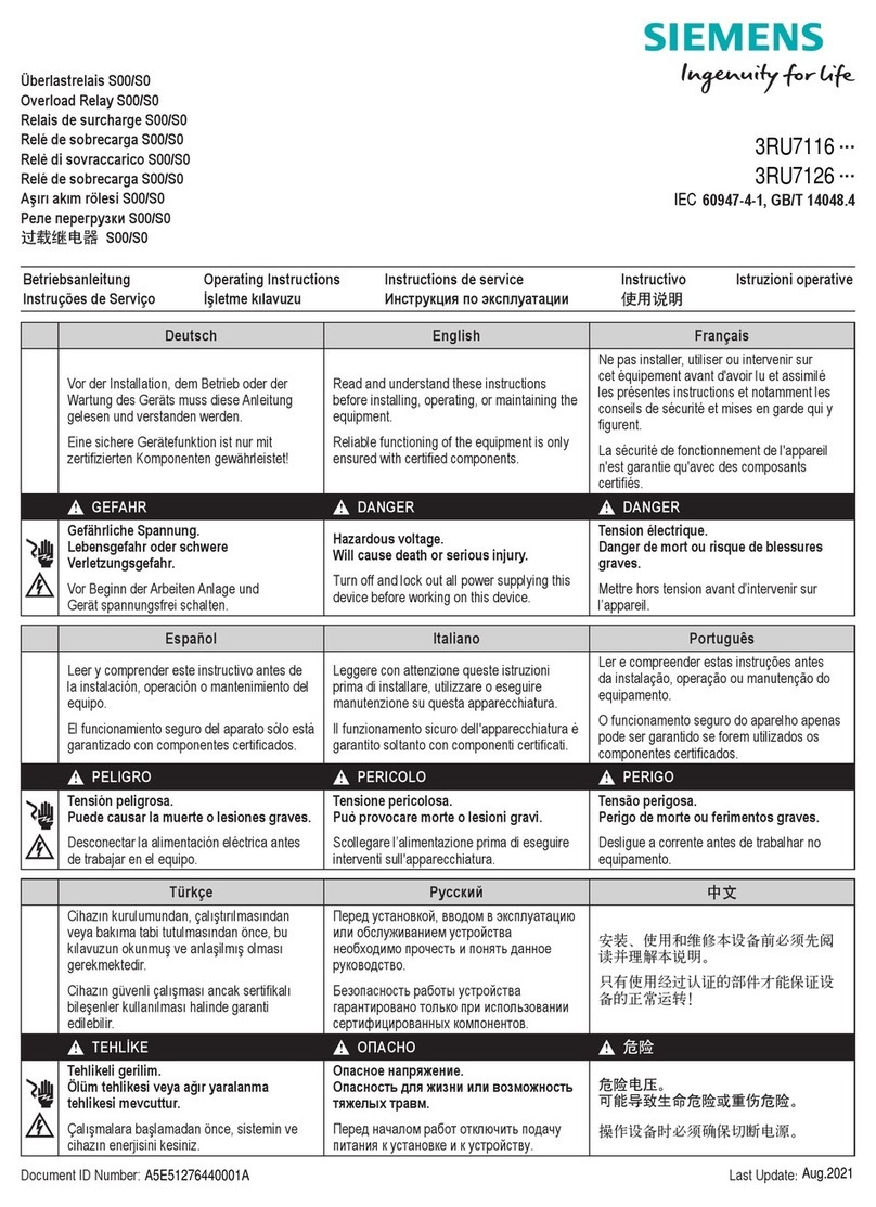
  9. Siemens 7UG0861-1BU20 User manual

Siemens 7UG0861-1BU20 User manual

1
s
Operating Instructions
Earth Fault Monitoring Relays
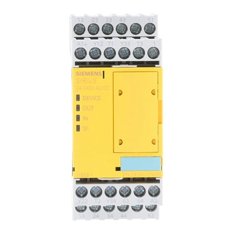
7UG0861-1BU20
7UG0
IEC 60947-5-1
IEC 60947-4-1
Please read and understand these instructions before installing,
operating, or maintaining the equipment.
DANGER
Hazardous voltage can cause death or serious injury.
Disconnect power before working on equipment.
CAUTION
Reliable functioning of the equipment is only ensured
with certied components.
Overvoltage category II
(Refer IEC 60947-1)
NOTICE
This product has been designed for environment A. Use of this product
in environment B may cause unwanted electromagnetic disturbances in
which case the user may require to take adequate mitigation measures.
Technical Data
Designation 7UG0861-1BU20
Type Earth Fault relay
Control voltage 85 - 270V AC/DC
Operating temperature 0 to 50°C
Trip modes Fault current: 10%-80% of rated current
CBCT current ranges:
- 160A
- 250A
- 630A
Trip Time delay 0 - 99.9 sec
Power consumption 4VA
7UG0861…
Terminal connections
Control
Voltage
MLFB Type
7UG09910 Core Balance CT 160 A, 3P
7UG09911 Core Balance CT 160 A, 4P
7UG09912 Core Balance CT 250 A, 3P
7UG09913 Core Balance CT 250 A, 4P
7UG09914 Core Balance CT 630 A, 3P
7UG09915 Core Balance CT 630 A, 4P
LED Indication Chart
Various condition ‘R1’ LED ‘R2’ LED
No Fault OFF OFF
Pre-Alarm OFF ON
Fault / Trip ON ON
Note:
7UG0991.CBCT (Core Balanced Current Transformer) is an
accessory to be used with 7UG0861... (Earth Fault relay)
For single phase applications, only the live and neutral needs
to be passed through the CBCT.
For 3 Phase 3 wire system, pass L1, L2, L3 through CBCT.
For 3 Phase 4 wire system pass L1, L2, L3 and N through
CBCT.
The Earth MUST NOT pass through the CBCT.
The distance between relay and CBCT should be kept as short
as possible
Use Screen, shielded cable or twisted pair cable between the
unit and CBCT for long distance (Greater than 1m).
7UG08... / 7UG09..
0.5 Nm / 0.4 Nm
Solid
1 x (0.75 to 2.5) mm2
2 x 0.5 to 2 x 1.5 mm2
Stranded with end sleeve
1 x (0.5 to 2.5) mm2
2 x (0.5 to 1.5) mm2
2
Menu Guide 7UG0861..
CONFIGURATION MENU
Press + for 3sec. to enter or exit conguration menu.
TO SCROLL THROUGH MAIN MENU PRESS + OR + KEYS
Relay1
Setting
Time Setting
for Relay1
Relay2
Setting
Hysteresis
Password
Factory set
MCCB
Rating
Power
ON delay
Frame
Rating
Fault
Current Setting
Relay1
Operation Mode
Latch
Recovery
time delay
Relay2
operation Mode
Trip time
delay
Relay
functions
Pre
Alarm
Hysteresis
Setting
Password
Enable / Disble
Set password
Factory set
Yes / No
MAIN MENU SUB MENU
Time Setting
for Relay2
Trip time
delay
Recovery
time delay
Latch
MCCB
Settings
Note: Appearance of shaded menus dependant on selection of other parameters
SUB MENU
MCCB Settings (MCb) Press to enter sub menu from main menu
Press to to scroll
through sub menu Press + or + to change parameter value
DISPLAY
(For 1sec) DESCRIPTION DEFAULT
VALUE RANGE CONDITION
Frame Rating
A
160, 250, 630
MCCB Rating
A
For different Frame
rating the MCCB
ratings are
160: 16, 20, 25, 32,
40, 50, 63, 80,
100, 125, 160
250: 40, 50, 63, 80,
100, 125, 160,
200, 250
630: 250, 315, 400,
500, 630
For selected
frame rating,
the default
value will be
minimum
MCCB rating
of that
particular
frame.
Relay 1 Settings (RL1) Press to enter sub menu from main menu
Press to to scroll
through sub menu Press + or + to change parameter value
DISPLAY
(For 1sec) DESCRIPTION DEFAULT
VALUE RANGE CONDITION
Set trip value
for fault
current
A
R1
10% to 80% of
selected MCCB
rating
Steps of 0.1A from 0
to 99.9A and Steps
of 1A beyond 100A
Eg. For MCCB
rating of
160A Set
value will be
from 16.0A
to 128A
Relay
operation
mode
R1
ON/OFF
ON : NC
(During Trip)
OFF : NO
(During Trip)
Latch
R1
ON/OFF
If latch is ON,
user has to
reset the unit
manually
when the
fault is
removed
Time Setting for Relay 1 (TM1) Press to enter sub menu from main menu
Press to to scroll
through sub menu Press + or + to change parameter value
DISPLAY
(For 1sec) DESCRIPTION DEFAULT
VALUE RANGE CONDITION
Trip time delay
S
R1
t
0.0 – 99.9 sec
Recovery time
delay
S
R1
off
t
0.0 – 99.9 sec
Power ON
delay
S
on
t
0.5 – 99.9 sec
Applicable for
Relay1 and
Relay2
3
Relay 2 Settings (RL2) Press to enter sub menu from main menu
Press to to scroll
through sub menu Press + or + to change parameter value
DISPLAY
(For 1sec) DESCRIPTION DEFAULT
VALUE RANGE CONDITION
Relay 2
Functions
R2
RL1 / PRE
If RL1 is
selected, all
the settings
done for RL1
& TM1 will be
automatically
set for RL2
and no other
parameter
of RL2 &
TM2 will be
prompted.
Pre Alarm
R2
50% – 100%
Will prompt
only if PRE is
selected for
Relay 2
Relay
operation
mode
R2
ON / OFF
ON : NC
(During Trip)
OFF : NO
(During Trip)
Latch
R2
ON / OFF
If Latch is
ON, user has
to reset the
unit manually
when fault is
removed
Time Setting for Relay 2 (TM2) Press to enter sub menu from main menu
Press to to scroll
through sub menu Press + or + to change parameter value
DISPLAY
(For 1sec) DESCRIPTION DEFAULT
VALUE RANGE CONDITION
Trip time delay
S
R2
tt
0.0 – 99.9 sec.
Recovery time
delay
S
R2
off
t
0.0 – 99.9 sec.
Hysteresis (HYS) Press to enter sub menu from main menu
Press to to scroll
through sub menu Press + or + to change parameter value
DISPLAY
(For 1sec) DESCRIPTION DEFAULT
VALUE RANGE CONDITION
Hysteresis
A
H
1% to 10% of Trip
current setting (SV)
Fault
condition
is removed
when fault is
H% less than
the Set Value
Password (PW) Press to enter sub menu from main menu
Press to to scroll
through sub menu Press + or + to change parameter value
DISPLAY
(For 1sec) DESCRIPTION DEFAULT
VALUE RANGE CONDITION
Password ENB / DIS
Enable /
Disable
password
protection
option
Set password 0-999
Will be
prompted
only when
Password
option is
enabled
Main Menu
Password
NOTE: PW option will be asked when
the user enter the cong. menu if
PW option is enabled in the cong
menu and the user has to enter the
password which he has set in the
S.PW (set password) option.
Factory set (RST) Press to enter sub menu from main menu
Press to to scroll
through sub menu Press + or + to change parameter value
DISPLAY
(For 1sec) DESCRIPTION DEFAULT
VALUE RANGE CONDITION
Reset
(Factory set) YES / NO
TEST & RESET FUNCTION LED ON LED OFF
KEY DESCRIPTION DISPLAY
(For 1sec) LED’s CONDITION
For TEST Press TST key
for > 2 sec.
R1 R2
Test is in Process.
Test passed
R1 R2
If test key is passed, OK
will be displayed till reset
button is pressed.
Test Failed
R1 R2
–
RST Press RST key
for > 2 sec.
Actual
Value
R1 R2
–
TRIP INDICATION Trip Indication on press of key: Trip value will be
displayed till the key is pressed.
RESET Press key for 3sec. to reset manually
Master Password: 753
Siemens Ltd.
DF-SGR-680-2016
Product development is a continuous process. Consequently
the data indicated in this Leaet is subject to change without
prior notice. For latest issue contact our sales ofces.
SACHIN ENTERPRISE
Disposal
Siemens product are environment friendly, which predominantly
consist of recyclable materials.
For disposals we recommend disassembling and separation into
following materials:
METALS: Segregate into Ferrous & Non Ferrous types for recycling
through authorised dealer.
PLASTICS: Segregate as per material type for recycling through
authorised dealer. Because of the long lifetime of Siemens
products the disposal guidelines may be replaced by other national
regulations when taking the product out of service.
The local customer care service is available at any time to answer
disposal-related questions
Dimensional drawings
7UG0861… 7UG0991..
s
35mm
Sr. No. MLFB A (mm) B (mm) C (mm) D (mm) E (mm) F (mm) G (mm) H (mm)
1 7UG09910 100 25 156 84 100 28 184 170
2 7UG09911 140 35 201 98 114 28 230 215
3 7UG09912
4 7UG09913 180 35 236 93 109 28 264 250
5 7UG09914
6 7UG09915 220 50 276 112 128 28 305 290
Customer Care Toll free no. 1800 209 0987 Email: [email protected] Order No. A5E37638690A

Other Siemens Relay manuals

Siemens 7SR224 User manual

Siemens

Siemens 7SR224 User manual

Siemens SIRIUS 3RF23 0 Series User manual

Siemens

Siemens SIRIUS 3RF23 0 Series User manual

Siemens 3VT9115-5GY31 User manual

Siemens

Siemens 3VT9115-5GY31 User manual

Siemens 7SR45 Argus User manual

Siemens

Siemens 7SR45 Argus User manual

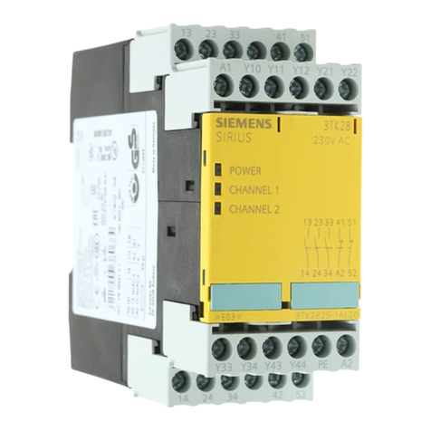
Siemens SIRIUS 3TK2824 A.20 Series User manual

Siemens

Siemens SIRIUS 3TK2824 A.20 Series User manual

Siemens SIPROTEC 7SJ80 User manual

Siemens

Siemens SIPROTEC 7SJ80 User manual

Siemens 62 Series Quick guide

Siemens

Siemens 62 Series Quick guide

Siemens SIRIUS 3RU6116 Series User manual

Siemens

Siemens SIRIUS 3RU6116 Series User manual

Siemens SIRIUS 3RU1.3 User manual

Siemens

Siemens SIRIUS 3RU1.3 User manual

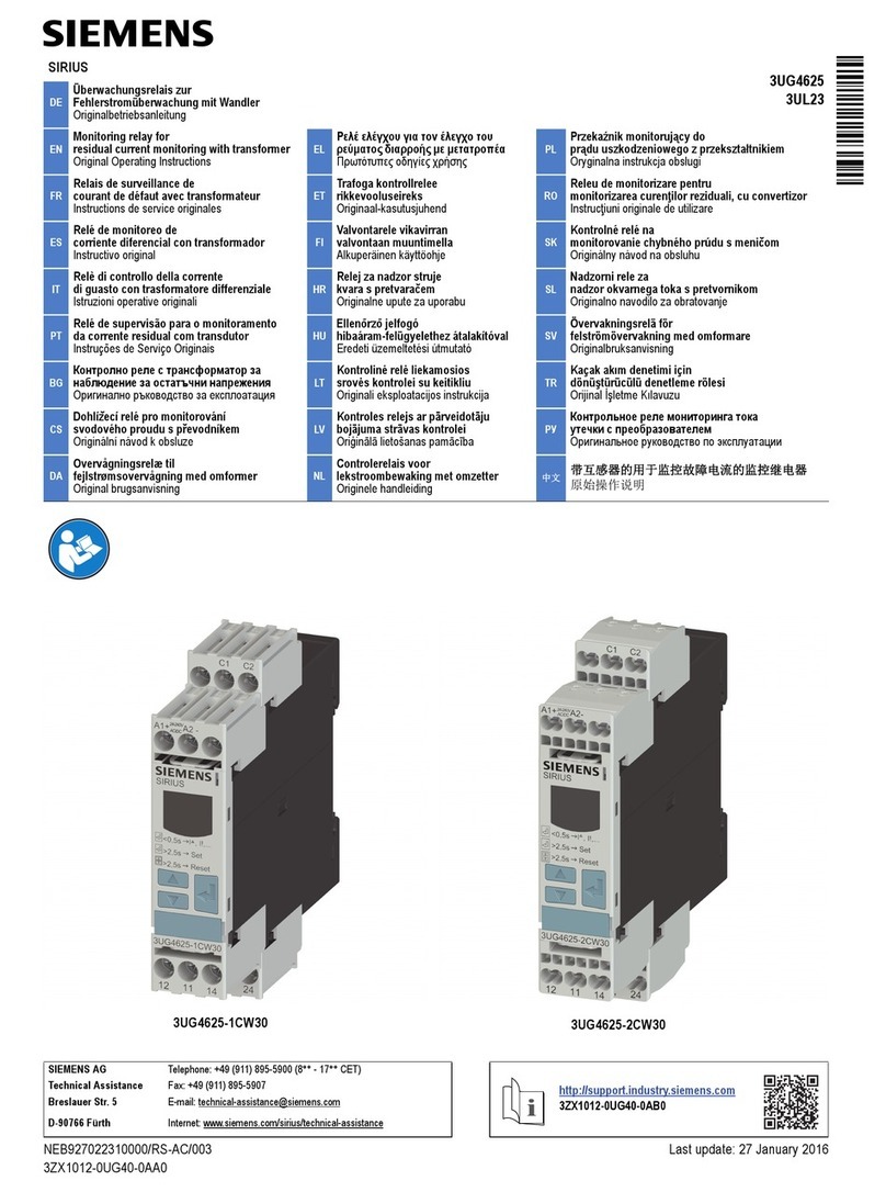
Siemens SIRIUS 3UG4512 Series User manual

Siemens

Siemens SIRIUS 3UG4512 Series User manual

Siemens 3RB23 User manual

Siemens

Siemens 3RB23 User manual

Siemens 7UG0 Series User manual

Siemens

Siemens 7UG0 Series User manual

Siemens SIPROTEC 7SJ62 User manual

Siemens

Siemens SIPROTEC 7SJ62 User manual

Siemens 7SR210 Argus User manual

Siemens

Siemens 7SR210 Argus User manual

Siemens 3VU2932-4 Series User manual

Siemens

Siemens 3VU2932-4 Series User manual

Siemens 48-HASA3M User manual

Siemens

Siemens 48-HASA3M User manual

Siemens SITRANS LVL200H User guide

Siemens

Siemens SITRANS LVL200H User guide

Siemens 3RB22 Training manual

Siemens

Siemens 3RB22 Training manual

Siemens SIRIUS 3RU1900-1A User manual

Siemens

Siemens SIRIUS 3RU1900-1A User manual

Siemens 7SR242 Duobias Operating manual

Siemens

Siemens 7SR242 Duobias Operating manual

Siemens 3RP25 User manual

Siemens

Siemens 3RP25 User manual

Siemens SIRIUS 3SU140 1E Series User manual

Siemens

Siemens SIRIUS 3SU140 1E Series User manual

Siemens 7SR17 Rho User manual

Siemens

Siemens 7SR17 Rho User manual

Siemens SIPROTEC 4 User manual

Siemens

Siemens SIPROTEC 4 User manual

Popular Relay manuals by other brands

ABB RELION REF610 Technical reference manual

ABB

ABB RELION REF610 Technical reference manual

F&F PCS-516 DUO manual

F&F

F&F PCS-516 DUO manual

Rockwell Automation Allen-Bradley Minotaur 440R installation instructions

Rockwell Automation

Rockwell Automation Allen-Bradley Minotaur 440R installation instructions

DMX4ALL DMX-RELAIS 8 INRUSH+ user manual

DMX4ALL

DMX4ALL DMX-RELAIS 8 INRUSH+ user manual

BRÖTJE SIS 3 SGB Assembly instructions

BRÖTJE

BRÖTJE SIS 3 SGB Assembly instructions

Pilz PNOZ X2.1VP operating instructions

Pilz

Pilz PNOZ X2.1VP operating instructions

Pilz PNOZ X3 Technical instructions

Pilz

Pilz PNOZ X3 Technical instructions

BECKWITH ELECTRIC M-0420 Instruction book

BECKWITH ELECTRIC

BECKWITH ELECTRIC M-0420 Instruction book

MSD Ignition 8961 installation instructions

MSD Ignition

MSD Ignition 8961 installation instructions

Dossena RECA/E8CC quick start guide

Dossena

Dossena RECA/E8CC quick start guide

Schweitzer Engineering Laboratories SEL-151C instruction manual

Schweitzer Engineering Laboratories

Schweitzer Engineering Laboratories SEL-151C instruction manual

Pilz PNOZ XE2 manual

Pilz

Pilz PNOZ XE2 manual

Haseman Electric RS-10PM user manual

Haseman Electric

Haseman Electric RS-10PM user manual

USR IOT usr-wifiio-83 user manual

USR IOT

USR IOT usr-wifiio-83 user manual

CleaverBrooks CB780 installation instructions

CleaverBrooks

CleaverBrooks CB780 installation instructions

BIG TREE TECH Relay V1.2 Operating	 instruction

BIG TREE TECH

BIG TREE TECH Relay V1.2 Operating instruction

Nibe FIGHTER 1320 manual

Nibe

Nibe FIGHTER 1320 manual

Trinity Newton+ user manual

Trinity

Trinity Newton+ user manual

manuals.online logo
manuals.online logoBrands
  • About & Mission
  • Contact us
  • Privacy Policy
  • Terms and Conditions

Copyright 2025 Manuals.Online. All Rights Reserved.