manuals.online logo
Brands
  1. Home
  2. •
  3. Brands
  4. •
  5. Siemens
  6. •
  7. Relay
  8. •
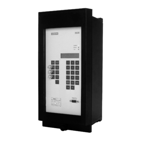
  9. Siemens Argus 8 7SG11 User manual

Siemens Argus 8 7SG11 User manual

Reyrolle
Protection
Devices
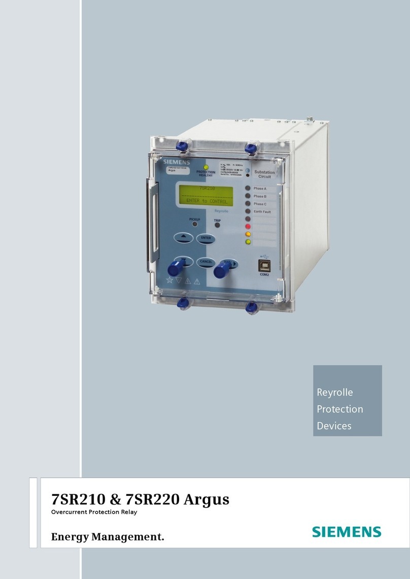
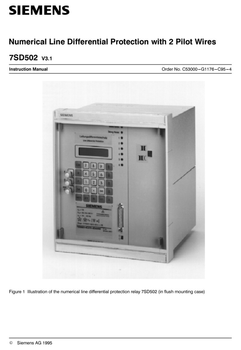
7SG11 – Argus 8
Voltage and Frequency Relays
Answers for energy
7SG11 Argus 8 Contents
The copyright and other intellectual property rights in this document, and in any model or article produced from it
(and including any registered or unregistered design rights) are the property of Siemens Protection Devices
Limited. No part of this document shall be reproduced or modified or stored in another form, in any data retrieval
system, without the permission of Siemens Protection Devices Limited, nor shall any model or article be
reproduced from this document unless Siemens Protection Devices Limited consent.
While the information and guidance given in this document is believed to be correct, no liability shall be accepted
for any loss or damage caused by any error or omission, whether such error or omission is the result of
negligence or any other cause. Any and all such liability is disclaimed.
©2010 Siemens Protection Devices Limited
Contents
Technical Manual Chapters
1 Description of Operation
2 Performance Specification
3 Relay Settings
4 Communication Interface
5 Applications Guide
6 Installation
7 Commissioning
8 Maintenance
9 Drawings
7SG11 Argus 8 Description of Operation
The copyright and other intellectual property rights in this document, and in any model or article produced from it
(and including any registered or unregistered design rights) are the property of Siemens Protection Devices
Limited. No part of this document shall be reproduced or modified or stored in another form, in any data retrieval
system, without the permission of Siemens Protection Devices Limited, nor shall any model or article be
reproduced from this document unless Siemens Protection Devices Limited consent.
While the information and guidance given in this document is believed to be correct, no liability shall be accepted
for any loss or damage caused by any error or omission, whether such error or omission is the result of
negligence or any other cause. Any and all such liability is disclaimed.
©2010 Siemens Protection Devices Limited
7SG11 Argus 8
Voltage and Frequency Relays
Document Release History
This document is issue 2010/02 The list of revisions up to and including this issue is:
Pre release
2010/02 Document reformat due to rebrand
Software Revision History
7SG11 Argus 8 Description of Operation
Contents
1Introduction..........................................................................................................................................4
3Protection Functions....................................................................................................................8
3.1 Voltage Blocking Element............................................................................................................8
3.2 Voltage Elements ........................................................................................................................8
3.3 NPS Overvoltage Elements.........................................................................................................9
3.4 NVD Overvoltage Elements.........................................................................................................9
3.5 Frequency Elements....................................................................................................................9
3.6 Two Systems Connection..........................................................................................................10
3.7 External Tripping .......................................................................................................................10
4Other Features ..........................................................................................................................10
4.1 Metering.....................................................................................................................................10
4.2 Data Storage .............................................................................................................................11
4.2.1 Waveform Records..........................................................................................................11
4.2.2 Event Records.................................................................................................................11
4.2.3 Fault Data Records .........................................................................................................12
4.3 Communications........................................................................................................................12
4.4 General Alarm Screens .............................................................................................................13
4.5 Default Instrument Screens .......................................................................................................13
4.6 Multiple Settings Groups. ..........................................................................................................13
4.7 Password Feature .....................................................................................................................13
4.8 Trip Circuit Supervision .............................................................................................................14
5User Interface ............................................................................................................................14
5.1 Liquid Crystal Display ................................................................................................................14
5.2 LED Indications .........................................................................................................................14
5.3 Keypad.......................................................................................................................................14
5.4 Navigating the Menu System.....................................................................................................14
Table of Figures
Figure 1 - Voltage Element....................................................................................................................... 8
Figure 2 - NPS Overvoltage Element....................................................................................................... 9
Figure 3 - NVD Overvoltage Element....................................................................................................... 9
Figure 4 - Frequency Element................................................................................................................ 10
Figure 5 - Display Menu Structure.......................................................................................................... 20
Tables
Table 1 - Argus 8 - 2 Pole Variants ...........................................................................................................................5
Table 2 - Argus 8 - 3 Pole Variants ...........................................................................................................................5
Table 3 - Output Relay Types ...................................................................................................................................6
Table 4 - Connection Table (E4 Versions) ..............................................................................................................16
Table 5 - Connection Table (E6 Versions) ..............................................................................................................17
Table 6 - Event Codes ............................................................................................................................................19
©2010 Siemens Protection Devices Limited Chapter 1 Page 2 of 20
7SG11 Argus 8 Description of Operation
Reference Material
[1] - REYDISP EVOLUTION : is a PC based relay support package which allows local or remote access to relays
for uploading settings, downloading event and disturbance records, reading real-time data and allowing control of
plant. The package is available from Reyrolle Protection and is compatible with all Argus range relays.
[2] - INFORMATIVE COMMUNICATIONS INTERFACE : a report detailing all aspects of the communications
protocol used in the Argus range of relays is available from Reyrolle Protection. The report reference is
434TM05B.
©2010 Siemens Protection Devices Limited Chapter 1 Page 3 of 20
7SG11 Argus 8 Description of Operation
1 Introduction
The Argus 8 series of Voltage and Frequency relays are numerical, multi-function devices, which have been
designed to be applied for the protection of generation, transmission, distribution and industrial systems.
•Argus 8 - 100 series provide under / over voltage, negative sequence overvoltage and neutral voltage
displacement functions.
•Argus 8 - 200 series provide under / over frequency functions in addition to the functions included in the
100 series.
•Argus 8 - 300 series provide identical functionality to the 200 series but have a faster frequency element
operate time. Suitable for 50Hz systems only.
The protection functions available in the range have many possible applications, some of which are mentioned
below :
Under / overvoltage elements :
Four independent elements are supplied, each of which can be set to operate for under or overvoltage conditions
and all having separate DTL time delay elements. These can be used to protect generators against overvoltages,
motors against loss of supply or applied as backup protection in the event of defective system regulating
equipment.
Negative phase sequence (NPS) overvoltage elements :
Two independent elements are supplied, each of which has a DTL time delay element. These can be used to
monitor the quality of the supply and protect plant or feeders against system unbalance.
Neutral voltage displacement (NVD) elements :
Two independent elements are supplied, each of which has a DTL time delay element. These can be used to
detect earth faults in high impedance earthed or isolated systems. For this feature, the residual voltage can be
measured directly from an open delta tertiary winding or calculated internally from the three phase voltage inputs.
The NVD elements include a third harmonic filter, which de-sensitises the elements to any superimposed third
harmonic frequencies.
Under / overfrequency elements :
Four independent elements are supplied, each of which can be set to operate for under or over frequency and all
having separate DTL time delay elements. These can be applied wherever frequency protection is required to
maintain system stability e.g. in load shedding schemes. The accuracy and security of operation of the numeric
algorithms enables the relay to be employed to detect any frequency abnormalities.
Blocking operation :
Each protection element can be blocked from operation by a user defined status input signal. In addition, the
voltage, frequency, and NPS elements can be blocked by the Voltage Blocking Threshold, which has a variable
setting range. Also, each frequency element can be blocked by any combination of the voltage elements starting.
Argus 8 series of Voltage and Frequency relays are part of the comprehensive range of Argus-platform based
numeric relays. These relays have extensive control functions, which are supplemented by advanced metering,
data storage and fibre optic communications. Supervisory and self-monitoring features give added confidence to
the user as well as reduced maintenance and down time. A menu-based interface gives user-friendly access to
relay settings, meters and operational data.
The relay conforms to the relevant IEC 60255 standards.
©2010 Siemens Protection Devices Limited Chapter 1 Page 4 of 20
7SG11 Argus 8 Description of Operation
The following table details the functions available in the Argus 8 - two pole variants which are supplied in the
Epsilon E4 case size. Note how the number and type of elements included depend upon the ‘Connection Setting’
parameter.
Protection Elements Available I/O Available
Catalogue
Number
Connection
Setting Voltag
e
Frequenc
y
NPS NVD
Direct
NVD
Calc.
Inputs Outputs
2Ph-Ph 4 - 2 - - 4 7
Ph-N+NVD 4 - - 2 -
Ph-Ph+NVD 4 - - 2 -
AG8 101-103
2 systems
A/B
4 - - - -
2Ph-Ph 4 4 2 - - 4 7
Ph-N+NVD 4 4 - 2 -
Ph-Ph+NVD 4 4 - 2 -
AG8 201-203
2 systems
A/B
4 - - - -
2Ph-Ph 4 4 2 - - 4 7
Ph-N+NVD 4 4 - 2 -
Ph-Ph+NVD 4 4 - 2 -
AG8 301-
303*
2 systems
A/B
4 - - - -
* Argus 8 types 301-303 are suitable for 50Hz systems only.
Table 1 - Argus 8 - 2 Pole Variants
The following table details the functions available in the Argus 8 - three pole variants which are supplied in the
Epsilon E6 case size. Note how the number and type of elements included depend upon the ‘Connection Setting’
parameter.
Protection Elements Available I/O Available
Catalogue
Number
Connection
Setting Voltag
e
Frequenc
y
NPS NVD
Direct
NVD
Calc.
Inputs Outputs
3Ph-Ph 4 - 2 - - 1 7
2Ph-
Ph+NVD
4 - - 2 -
AG8 104-106
3Ph-N+NVD 4 - 2 - 2
AG8 107-109 All features as above 9 7
AG8 110-112 All features as above 5 11
3Ph-Ph 4 4 2 - - 1 7
2Ph-
Ph+NVD
4 4 - 2 -
AG8 204-206
3Ph-N+NVD 4 4 2 - 2
AG8 207-209 All features as above 9 7
AG8 210-212 All features as above 5 11
3Ph-Ph 4 4 2 - - 1 7
2Ph-
Ph+NVD
4 4 - 2 -
AG8 304-
306*
3Ph-N+NVD 4 4 2 - 2
AG8 307-309 All features as above 9 7
AG8 310-312 All features as above 5 11
* Argus 8 types 304-312 are suitable for 50Hz systems only.
Table 2 - Argus 8 - 3 Pole Variants
©2010 Siemens Protection Devices Limited Chapter 1 Page 5 of 20
7SG11 Argus 8 Description of Operation
2 Hardware Description
2.1 General
All of the Argus range of relays share common hardware components and modules. The design for the
mechanical arrangement of the relays has been carefully chosen to provide a high level of EMI
screening using multi-layer PCB’s with ground planes, RFI suppression components and earthed
metal screens. The internal arrangement has been divided into noisy and quiet areas in order to
improve noise immunity and reduce RFI emissions. The only direct connection from the quiet
components to the external environment is via the optical serial communications interface, which is
immune to radiated or conducted interference.
2.2 Analogue Inputs
The input stage of an Argus 8 relay measures either two or three voltage quantities depending upon the particular
variant. Over the range of 5 Vrms to 200 Vrms it maintains accuracy within ±1% (or 0.25V) over the declared
frequency performance range. The wide measuring range of the input stage allows for either phase-phase or
phase-neutral connections e.g. 110Vrms or 63.5Vrms nominal voltages.
Note : on relay variants which have a 2Ph-Ph connection setting, the 3rd phase voltage can be calculated from the
two known phases if the external connection is connected phase-phase.
In order to ensure high accuracy voltage, frequency and sequence component calculations the voltage
signals are sampled at 32 samples per cycle for both 50Hz and 60Hz system frequencies. The high
sampling rate provides high accuracy and quality waveform storage records, which are stored at a rate
of 16 samples per cycle.
2.3 Output Relays
Argus 8 relays have a variety of output contact types available depending upon the case size and expansion card
option. The full range is given in Table 3.
Output Relays Available
Catalogue Number
C/O Contact N/O Contact N/C Contact
AG8 101-103 1 5 1
AG8 201-203 1 5 1
AG8 301-303 1 5 1
AG8 104-106 3 4 -
AG8 204-206 3 4 -
AG8 304-306 3 4 -
AG8 107-109 3 4 -
AG8 207-209 3 4 -
AG8 307-309 3 4 -
AG8 110-112 3 8 -
AG8 210-212 3 8 -
AG8 310-312 3 8 -
Table 3 - Output Relay Types
All output relays are fully user configurable and can be programmed to operate from any or all of the protection
functions. In addition, a watchdog feature within the relay can be mapped to any of the output relays. A
changeover or normally-closed contact is generally required for this.
All output relays are of the same design and therefore each is capable of handling direct circuit breaker-tripping
duty.
Output relays can be set to remain energised for a minimum time of between 100-500msec. If required, however,
outputs can be programmed to operate as latching relays. These latched outputs can be reset by either pressing
the TEST/RESET button, by energising a status input or by sending an appropriate communications command.
A trip test feature is provided to exercise the output contacts.
For a list of terminal numbers and their usage see Tables 4 and 5 at the back of this section.
2.4 Status Inputs
©2010 Siemens Protection Devices Limited Chapter 1 Page 6 of 20
7SG11 Argus 8 Description of Operation
On two pole Argus 8 variants there are a total of 4 status inputs available in the relay. Of these three have a
common negative supply and one is electrically isolated from the rest.
Standard three pole Argus 8 relays have 1 status input. One type of expansion card includes an extra 4 status
inputs giving a total of 5. Another type of expansion card includes an extra 8 status inputs giving a total of 9.
Tables 1 and 2 show the number of status inputs available for each type of relay.
All status inputs are fully user programmable and each has a pick-up and drop-off timer. These timers allow
software filtering to be applied, which provides security in the presence of any induced A.C. voltages in the
external wiring. If high-speed operation is required then the pick-up delay should be set to zero.
Each of the status inputs can be programmed to perform one of the following functions :
•Inhibit operation of any one or more protection functions.
•Select an alternative settings group.
•Trigger storage of a waveform record.
•Synchronise the real-time clock.
•Reset latched output relays.
•Energise an output relay.
•Register a Trip by an external device.
•Raise an alarm annunciation.
Additionally, each status input can have its operating logic inverted with the Status Invert feature.
For a list of terminal numbers and their usage see Tables 4 and 5 at the back of this section.
2.5 Self Monitoring
The relay incorporates a number of self-monitoring features. Each of these features can initiate a controlled reset
sequence, which can be used to generate an alarm output. In addition, the Protection Healthy LED will give visual
indication.
A watchdog timer continuously monitors the microprocessor and the relay program memory is continuously
checked for data corruption using a cyclic redundancy check (CRC) routine. The internal voltage supply rails are
also continuously supervised and the microprocessor is reset if any of the rails are detected to be outside of their
working ranges. Any failure is detected in sufficient time so that the microprocessor can be shut down in a safe
and controlled manner.
2.6 Measuring Principles
The input phase voltages to the relay are passed through voltage transformers, which step down the phase
voltages to levels which are suitable for the electronic input stage of the relay. The transformers also provide
essential isolation between the power system and the relay. The output of the transformers are differential signals
which are passed through lowpass filters and then from the voltage transformer board to the processor / analogue
board. Here the signals are fed to differential amplifiers which have excellent common-mode rejection. These will
reject any high frequency noise which may have coupled to the differential pair signals.
The single-ended output from the differential amplifiers is then fed to gain switching amplifiers which maximise the
signal gain to provide optimum measurement resolution. From here the signals are fed to the ADC where they are
sampled at a rate of 32 samples per power system cycle. (The dynamic range of the analogue-to-digital converter
(ADC) is increased with this gain switching method.)
The main signal processing algorithm in the relay is a discrete fourier transform (DFT) which is performed on each
phase input. The DFT extracts the power system fundamental frequency component from the input voltages,
effectively filtering out noise, D.C. and harmonics. The DFT is tuned for either 50 or 60Hz, depending upon the
system frequency setting. Output from the DFT calculations are real and imaginary components for each voltage
input.
The real and imaginary components are used to derive the magnitude quantity, which is then scaled to give a
RMS value. Part of the DFT calculation includes extra filtering which smoothes the real and imaginary
components, giving reduced ripple on the RMS calculation for off-system frequency conditions. In addition, a
lookup table is used to compensate for magnitude variations from the output of the RMS calculation for 47-62Hz
frequencies.
The real and imaginary components output from the DFT module are also used to derive the phase of the input
signal. The frequency is derived from the rate-of-change of the phase angle calculation. In addition, negative
phase sequence (NPS) and zero phase sequence (ZPS) quantities are also derived from the output of the DFT
calculation. The DFT ensures that D.C. and harmonics are rejected and so guarantees accurate and stable
©2010 Siemens Protection Devices Limited Chapter 1 Page 7 of 20
7SG11 Argus 8 Description of Operation
sequence calculations. The ZPS calculation, which is used in the neutral voltage displacement (NVD) function
also benefits from excellent inherent 3rd harmonic rejection.
All relays are fully calibrated during manufacture using accurate voltage source equipment. Calibration
coefficients are stored in EEPROM and are used by the processor to compensate for any inaccuracies in the
input stage, which have been introduced by the analogue circuits. Errors in magnitude and phase are eliminated
using this method.
3 Protection Functions
3.1 Voltage Blocking Element
The voltage blocking element acts as a block to the Voltage, Frequency and NPS elements in the relay. If all
phase voltages fall below the threshold level then the blocking operation will operate. This block does not apply to
the NVD elements.
•For 3 pole relay variants: Voltage blocking is applied when all 3 phases fall below the threshold level.
(If set to 2Ph-Ph+NVD, then when the two phases fall below).
•For 2 pole relay variants (set as 2Ph-Ph): Voltage blocking is applied when both phases fall below the
threshold level.
The setting range for the voltage blocking threshold is OFF, 1V - 100V with a 1V step . This element is required
mainly for undervoltage operation conditions. Under normal circumstances, if all phase voltages fall below the
undervoltage setting, a trip output would be the expected response. However, in some applications e.g. auto-
reclose schemes, having an undervoltage relay trip when the line is de-energised during the auto-reclose
sequence is not usually desirable. Blocking the undervoltage operation in this situation can be achieved by using
the Voltage Blocking Threshold, which should generally be set above the level of expected induced voltages on
the line.
(See Applications Guide Section 2.2 for more information regarding this element).
3.2 Voltage Elements
Each version of the Argus 8 relay has 4 voltage elements as standard. These can be configured to be either
undervoltage (U/V) or overvoltage (O/V) elements. If the input voltages exceed the pickup level, whether U/V or
O/V, then each element operates through a gate, which selects operation from any one phase or all phases. At
this point the element can still be inhibited from starting, using either a status input inhibit or if the input voltages
are below the voltage blocking threshold level. Figure 1 shows the basic operation of each voltage element. The
‘event’ and ‘instrument’ labels in the diagram indicate where this type of information is generated.
VAPickup Value
VBPickup Value
VCPickup Value
Any 1
or
All
V Element O/P Phases
Setting Select
&
1
Status Input
(VA & VB & VC)
☯
V Block Threshold
V Element
Starter
DTL
Event
Instrument
Event
Trip
Instrument
Event
Instrument
Event
(V Element Inhibit)
Block
Figure 1 - Voltage Element
The voltage elements each have a variable hysteresis setting which allows the user to vary the pick-up - drop-off
ratio for a particular element.
©2010 Siemens Protection Devices Limited Chapter 1 Page 8 of 20
7SG11 Argus 8 Description of Operation
3.3 NPS Overvoltage Elements
Some Argus 8 variants have, depending upon their configuration, 2 NPS overvoltage elements. If the NPS (V2)
input exceeds the setting value the starter will pickup unless any of the inhibits are enabled. Figure 2 shows the
basic operation of each NPS overvoltage element. The ‘event’ and ‘instrument’ labels in the diagram indicate
where this type of information is generated.
NPS (V2) Pickup Value &
1
Status Input
(VA & VB & VC)
☯
V Block Threshold
NPS
Element
Starter
DTL
Instrument
Event
Trip
Instrument
Event
Instrument
Event
Event
Block
(V2 Element Inhibit)
Figure 2 - NPS Overvoltage Element
3.4 NVD Overvoltage Elements
Some Argus 8 variants have, depending upon configuration, 2 neutral voltage displacement (NVD) overvoltage
elements. The neutral or residual voltage can be measured directly from an open delta tertiary winding or
calculated internally from the three phase voltage inputs.
If the relay is configured so that the residual voltage is measured directly, then this value is fed to the element
starter directly. Also, a 3Vo V.T. ratio setting will be made available. If however, the residual is calculated from the
3 phase input voltages, then 3 x Vo is fed to the element starter. (Vo is the zero sequence voltage ).
If the NVD input exceeds the setting value the starter will pickup unless an inhibit is enabled. Figure 3 shows the
basic operation of each NVD overvoltage element. The ‘event’ and ‘instrument’ labels in the diagram indicate
where this type of information is generated.
3 x ZPS (3Vo) Pickup Value &
Status Input
NVD
Element
Starter
DTL
Instrument
Event
Trip
Instrument
Event
Instrument
Event
Block(3Vo Element Inhibit)
Figure 3 - NVD Overvoltage Element
3.5 Frequency Elements
Argus 8 - 200 series variants have 4 frequency elements as standard. These can be configured as either
underfrequency (U/F) or overfrequency (O/F). Each element can be inhibited in four different ways :-
1. If all phase voltages fall below the voltage blocking threshold level.
2. Via a status input inhibit signal.
3. Via any combination of voltage elements starting.
©2010 Siemens Protection Devices Limited Chapter 1 Page 9 of 20
7SG11 Argus 8 Description of Operation
4. If all of the phase voltages fall below 29V. This is independent of the voltage blocking threshold and
is required to ensure that the frequency accuracy claims are within ±10mHz. (Below 29V the frequency accuracy
deteriorates marginally).
Figure 4 shows the basic operation of the frequency elements. The ‘event’ and ‘instrument’ labels in the diagram
indicate where this type of information is generated.
F Element Pickup Value &
1
Status Input
(VA & VB & VC)
☯
V Block Threshold
Frequency
Element
Starter
DTL
Event
Instrument
Event
Trip
Instrument
Event
Instrument
Event
V Element Inhibit
(VA & VB & VC)
☯
29Vrms
Block
(F Element Inhibit)
Figure 4 - Frequency Element
The frequency calculation is performed on data from one input phase only. If all phase voltages are above an
internal threshold of 29V, then the frequency calculation will be derived from the phase A input. If however, phase
A falls below 29V, then the calculation will automatically switch to phase B data. During the switchover process
the last frequency value measured is held until phase B returns a valid frequency answer. This will take
approximately 180ms. The switchover precedence is A-B-C and as each phase recovers its voltage then the
frequency calculation is switched back to this phase. This method ensures that the frequency calculation is
performed on a solid system voltage and not on low levels of input voltage where noise could cause incorrect
calculation.
3.6 Two Systems Connection
Two pole Argus 8 variants have a ‘2 Systems A/B’ connection setting. This setting re-configures the relay to
become a 4 element voltage relay but with the ability to assign the voltage elements to two different systems.
System A has voltage elements VE1 and VE2 assigned to it and System B has VE3 and VE4 assigned to it.
The System A input voltage is applied at the Va / Vab input terminals. System B is applied at the Vo / Vbc input
terminals.
3.7 External Tripping
Any status input can be programmed to receive a trip signal from another device. The status input should firstly be
mapped to the trip output contact in the Output Configuration Menu, so that energisation of the status input results
in a trip signal being issued. If the same trip contact is specified in the ‘Fault trigger’ setting then the relay will
switch to the fault data mode and indicate that an external trip has occurred.
4 Other Features
4.1 Metering
The Argus metering feature provides real-time data available from the relay fascia in the ‘Instruments Mode’ or via
the communications interface. The following displays are available :
•Primary RMS volts for VA, VB, VC and VO (alternatively VAB, VBC, VCA)
•Secondary RMS volts for Va, Vb, Vc, V1, V2 and Vo (alternatively Vab, Vbc, Vca)
©2010 Siemens Protection Devices Limited Chapter 1 Page 10 of 20
7SG11 Argus 8 Description of Operation
•System frequency
•Output relay status
•Digital input status
•General alarm screen
•Trip counter
•Power on counter
•Number of waveforms recorded
•Number of events stored
•Date - displayed in DD/MM/YY format
•Time - displayed in HH:MM:SS format
•Starter information for Voltage, Frequency, NPS and NVD elements
Note : the instrument displays are updated as often as the software routines can service them, however the RMS
voltage measurands have a response time of approximately 500msec.
Figure 5 shows the display menu structure from where the available instruments can be accessed. Note that
pressing the Test/Reset key can clear three of the instruments, the Trip Counter, Waveforms and Events.
4.2 Data Storage
Details of relay operation are recorded in three forms, namely Waveform records, Event records and Fault Data
records. All records are time and date stamped with a year 2000 compatible real time clock which maintains the
time even when the relay is de-energised [see Note below]. Time and date can be set either via the relay fascia
using appropriate commands in the System Config menu or via the communications interface. In the latter case,
relays connected in a network can be synchronised by a global time sync command.
Alternatively, synchronising pulses can be received via a status input. To use this feature one of the status inputs
has to be assigned to the ‘Clock Sync’ feature in the Status Config menu. Additionally the ‘Clock Sync Period’
setting in the System Config menu should be set to either ‘seconds’ or ‘minutes’. If ‘seconds’ are selected then the
energisation of the selected status input will result in the clock being synchronised to the nearest second with the
milliseconds set to zero. If ‘minutes’ are selected then the clock is synchronised to the nearest minute with both
seconds and milliseconds set to zero.
Note : the real-time clock, waveform records and event records are all maintained, in the event of loss of auxiliary
d.c. supply voltage, by the backup storage capacitor. This capacitor has the ability to maintain the charges on the
real-time clock IC and the SRAM memory device for typically 2-3 weeks time duration. This time, however, is
influenced by factors such as temperature and the age of the capacitor and could be shorter.
4.2.1 Waveform Records.
The waveform record feature stores analogue and digital information for the voltage inputs, status inputs and
output relays. The waveform record is 1.0 second long (0.833sec at 60Hz) with a sampling resolution of 16
samples per cycle. The recorder feature has the ability to store records for the previous five trip operations of the
relay. These are labelled 1-5 with 1 being the most recent record.
The waveform recorder can be triggered in the following ways ;
•Via the waveform trigger status input signal.
•From any element Trip operation, including, Voltage, Frequency, NVD and NPS elements.
•Via the IEC870-5-103 communications interface.
The waveform recorder has a settable pre-fault triggering capability.
4.2.2 Event Records
The event recorder feature allows the time tagging of any change of state (event) of the relay. As an event occurs,
the actual event condition is logged as a record along with a time and date stamp to a resolution of 5ms. There is
capacity for a maximum of 500 event records to be stored in the relay and when the event buffer is full, any new
record will over-write the oldest. The following events are logged :
©2010 Siemens Protection Devices Limited Chapter 1 Page 11 of 20
7SG11 Argus 8 Description of Operation
•Change of setting (though not the actual setting change). Also indication of which group of settings is
active.
•Change of state of each output relay.
•Change of state of each status Input.
•Change of state of any of the protection functions of the relay.
•Trip indication reset
•Trip test.
•Trip supply failure.
For a full list of all the events available see Table 6.
4.2.3 Fault Data Records
When issuing a trip output under fault conditions, the Argus 8 relay will illuminate the Trip LED, store a fault
record and display the fault indication screen. The fault indication screen displays a summary of the fault data
record, giving immediate, easily understood information on what has occurred. It displays date (DD/MM), time
(HH:MM:SS) and the poles which were picked up when the trip signal was issued e.g.
25/04 17:25:51
TRIP A B C
This display is held until the TEST/RESET button is pressed, upon which the LED will turn off and any latched
output relays are reset. The relay enters ‘Fault Data Display Mode’ at which point the fault indication screen is
replaced by a more detailed scrolling fault data display. This shows date and time of fault and for each pole the
elements which were picked up and the voltages measured at the time of trip e.g.
FAULT 1 25/04/00 17:25:51.5400 G1, VAB VE1 VE2 VE3 VE4 110.22V, Vo <3VoE1> <3VoE2> 110.215V,FE1
FE2 FE3 FE4 50.499Hz
FAULT 1
<< Fault Data >>
The fault record is viewed in the ‘Fault Data Display Mode’ of the menu system and can be viewed again at a later
date. The relay will store the last 10 fault records, which are numbered 1-10, with 1 being the most recent record.
To view them, scroll downwards using the button.
Depending upon the relay application, some of the protection elements may not be used for tripping purposes but
for alarm purposes. In these cases it would be undesirable for the Argus to light the Trip LED and give fault
indication. It is therefore necessary to define a ‘Fault’ for the cases where a trip is issued. A ‘Fault Trigger’ setting
exists in the Data Storage Menu, which allows a fault condition to be defined by selecting any combination of
output relays as tripping outputs. The Trip LED and the fault record storage will be triggered when any of the
selected output relays are energised. Note that a trip output can still be generated even if the fault trigger setting
is not used, though no trip indication will be given.
Fault records are stored in non-volatile memory.
4.3 Communications
A fibre optic communication port is provided which gives superior EMC performance. Communication is
compatible with the IEC870-5-103 FT 1.2 transmission and application standards. For communication with the
relay via a PC (personal computer) a user-friendly software package, REYDISP EVOLUTION [1], is available to
allow transfer of the following:
•Relay Settings
•Waveform Records
•Event Records
•Fault Data Records
•Instrument and meters
•Control Functions
Communications operation is described in detail in Section 4 of this manual.
©2010 Siemens Protection Devices Limited Chapter 1 Page 12 of 20
7SG11 Argus 8 Description of Operation
4.4 General Alarm Screens
The Argus 8 relay has an independent display function that provides up to nine General Alarm screens, each of
which may be programmed by the user to display a message associated with an external alarm.
Within the System Config Menu, each alarm message can be text edited by the user to display up to 13
characters. Also, each alarm can be user mapped to any status input, via the Status Config Menu, so that on
energisation of that input the associated alarm message is automatically displayed. Where more than one
General Alarm is raised then the display will scroll right to left to show all energised screens sequentially, with
screens separated by a ‘+’ sign. If required, more than one alarm may be mapped to a single status input,
allowing long messages to be displayed.
The message will appear on the LCD for the duration of the time that the status input is energised.
General Alarms
<< Alarm1 + Al<<
4.5 Default Instrument Screens
The menu presentation of the various instruments allows the user to view a single screen at a time. However, for
in-service use, it is desirable that a small number of high interest, user selectable, screens are presented
automatically by default without user intervention. The instrument screens of interest to the user e.g. those
required to be presented to a visiting engineer for record purposes can be selected by the user by pressing
ENTER when viewing the required screen. On pressing ENTER a ‘Screen Set As Default’ message will be
flashed up and a ‘’ will appear at the top right of that screen. The ‘’ indicates that a screen is a ‘default screen’.
To de-select a default screen, simply press ENTER while on that particular screen and a ‘Screen Cleared As
Default’ message will be flashed up. The ‘’ symbol will be cleared.
Frequency
50.003Hz
If no keys have been pressed for a pre-determined time the relay will jump to the default instrument display
regardless of where the menu system has been left by the user. It will then scroll through each of the selected
default instruments and remain on each for 5 seconds. The main timer, which sets the time to elapse before the
relay goes into the default instruments mode is found in the System Config Menu. This is the Default Screen
Timer setting and it can be set to a range of values from 10 seconds to 1 hour. See relay settings, Section 3 of
this manual.
If any General Alarm is raised, then the general alarm screen will be presented in the default screen sequence.
The general alarm screen, which has a scrolling display, will present one pass of its display message.
Any key press while in the default screen sequence will result in a return to the ‘Relay Identifier’ screen at the top
of the menu structure.
4.6 Multiple Settings Groups.
Argus relays provide eight alternative setting groups, making it possible to edit one group while the relay
protection algorithms operate using another ‘active’ group. An indication of which group is being viewed is given
by the ‘Gn’ character in the top left of the display. The relay can then be switched from one group of settings to
another to suit alterations in the power system configuration. Changeover will occur within 25ms.
A change of group can be achieved either locally at the relay fascia, remotely via a communication interface
command or by energisation of a status input. In the case of the latter method, the ‘Settings Group Select’ setting
is used to configure any one (or more) of the status inputs to select a settings group. The selected group is then
made active if the status input is energised and remains active for as long as the input remains energised.
4.7 Password Feature
The programmable password feature enables the user to enter a 4 character alphanumeric code to secure access
to the relay settings. The relay is supplied with the password set to ‘NONE’ which means that the password
feature is not activated. Once a password has been entered then it will be required thereafter to change settings.
It can, however, be de-activated by using the password to gain access and by resetting it back to ‘NONE’.
As soon as the user attempts to change a setting the password is requested before any setting alterations are
allowed. Once the password has been validated, the user is ‘logged on’ and any further changes can be made
without re-entering the password. If no more changes are made within 1 hour then the user will automatically be
‘logged off’, re-enabling the password feature.
©2010 Siemens Protection Devices Limited Chapter 1 Page 13 of 20
7SG11 Argus 8 Description of Operation
Note that the password validation screen also displays a numerical code. If the password is lost or forgotten, this
code can be communicated to Reyrolle Protection by authorised personnel, and the password can be retrieved.
4.8 Trip Circuit Supervision
A trip circuit supervision feature is provided within the relay. The Argus 8 can monitor its own trip circuit by
configuring one of its status inputs using the ‘Trip Circuit Fail’ setting and connecting the status input into the trip
circuit. Indication is then given instantaneously of ‘Trip Circuit Fail’ should a fault be detected and this display also
identifies which input has detected the fault. Since the status inputs can be programmed to operate output
contacts, an alarm can be also generated from the trip circuit supervision feature.
See Section 5 - Applications Guide, subsection 2.6 for more details on the trip circuit supervision scheme.
5 User Interface
The user interface is designed to provide a user-friendly method of entering settings and retrieving data from the
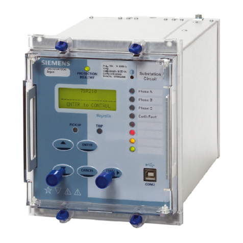
relay. The relay fascia includes a 16 character by 2 line, backlit, liquid crystal display (LCD), 3 light emitting
diodes (LED) and 5 push buttons.
5.1 Liquid Crystal Display
The liquid crystal display is used to present settings, instrumentation and fault data in a textual format. To
conserve power the display backlighting is turned off if no push buttons are pressed for 5 minutes. After one hour
the whole display is de-activated except if the display is left in the ‘Instruments Mode’ where it remain visible
permanently so that instruments can be displayed continuously. Also, if any default instruments have been
selected then the display will not power down, only the backlight will turn off. Once the backlight is turned off, any
following key press will turn the backlight on without changing the display.
5.2 LED Indications
The following indications are provided :
•Protection Healthy – Green LED (flashes with fault).
This LED is solidly illuminated to indicate that DC volts have been applied to the relay and that the relay is
operating correctly. If the internal relay watchdog detects a permanent fault then this LED will continuously flash.
•Starter – Yellow LED (self resetting).
This LED indicates that any of the protection element starters are operating.
•Trip – Red LED (latched).
This LED indicates that a trip as defined by the user has occurred. Such a trip may be issued by any of the relay’s
protection functions.
5.3 Keypad
Five pushbuttons are used to control the functions of the relay. They are labeled ENTER and CANCEL.
Note that the button is also labeled TEST/RESET.
When the relay front cover is in place only the and buttons are accessible. This allows only read access to all
the menu displays. It is not possible to change settings.
5.4 Navigating the Menu System
The display menu structure is shown in Figure 5. This diagram shows the three main modes of display, which are
the Settings Mode, Instruments Mode and the Fault Data Mode.
On relay start up the user is presented with a default relay identifier,
ARGUS 8
Factory Settings
which shows that the relay has been set with the standard factory default settings. The top line of the LCD can be
changed to some user-definable identifier or code if preferred.
©2010 Siemens Protection Devices Limited Chapter 1 Page 14 of 20
7SG11 Argus 8 Description of Operation
Pressing the key on this display initiates an LED test. Pressing at this display allows access to the three
display modes which are accessed in turn by pressing the key.
The ‘Settings Mode’ contains up to 10 setting sub-menu’s. (Note :- this number can vary depending upon relay
configuration). These hold all of the programmable settings of the relay in separate logical groups. The sub
menu’s are accessed by pressing the key. This enters the sub menu and presents a list of all the settings within
that sub menu. Pressing the key scrolls through the settings until after the last setting in the group the next sub
menu is presented. Access to this group is via the same method as before. If a particular sub menu is not
required to be viewed then pressing the key will skip past that particular menu and present the next one in the
list. Note that all screens can be viewed even if the password is not known. The password only protects against
unauthorised changes to settings.
While viewing an editable screen pressing the ENTER key allows the user to change the displayed data. The
editable field will be indicated by a flashing character(s). Pressing or scrolls through the available setting
values or, pressing the key moves right through the edit fields. Note that all settings can be incremented or
decremented using the or keys and they all wrap-around so that to go from e.g. a setting minimum value to
the maximum value it is quicker to press the key, rather than scroll up through every setting. Also, to facilitate
quicker setting changes an acceleration feature is available which if or are depressed and held, then the rate
of scrolling through the setting values increases.
If CANCEL is pressed during a setting change operation the original setting value is restored and the display is
returned to the normal view mode.
If changes are made to the setting value then pressing ENTER disables the flashing character mode and displays
the new setting value. This is immediately stored in non-volatile memory.
Note : the relay exhibits a method of hiding settings which are not relevant to a particular customer scheme which
is known as setting dependencies. Some settings are dependant on others being enabled and if a function is not
enabled then associated settings are not displayed e.g. if Voltage Element 1 is not required then set,
Gn V Element 1 Operation to OFF ; the following associated settings will not be displayed ;
Gn V Element 1 Setting,
Gn V Element 1 Delay,
Gn V Element 1 Hysteresis,
Gn V Element 1 O/P Phases,
Also hidden are all associated output relays options and status input inhibits.
There are many examples of setting dependencies and care must be taken to ensure a function is enabled before
looking for other associated settings which otherwise would be hidden.
The ‘Instruments Mode’ contains a maximum of 17 instruments. This number is dependent upon the relay
configuration and therefore some instruments may not be displayed. Pressing the key scrolls down through the
list of instruments and pressing scrolls up through them. For more information on the relay’s instruments see
Sections 4.1 and 4.5.
The ‘Fault Data Mode’ can contain a maximum of 10 fault records. These are accessed in the same way as the
other display modes. For more information on the fault record displays see Section 4.2.3.
For a complete list of all possible settings see Section 3 – of this manual. This section also shows all setting
ranges and factory default values, as well as including a brief description of each setting function.
©2010 Siemens Protection Devices Limited Chapter 1 Page 15 of 20
7SG11 Argus 8 Description of Operation
Function Terminal Terminal Function
Va / (Vab) Start 1 2
Finish Va / (Vab)
Vo / (Vbc) Start 3 4
Finish Vo / (Vbc)
Status Input 1 (+) 5 6
(–) Status Input 1
Relay 1 (N/C) – 7 8
– Relay 1 (N/C)
Relay 2 (N/O) – 9 10
– Relay 2 (N/O)
Relay 4 (N/O) – 11 12
– Relay 4 (N/O)
Aux. Volts (+) 13 14
(–) Aux. Volts
Earth
15 16
– Relay 3 (N/O)
Relay 3 (COM) – 17 18
– Relay 3 (N/C)
Relay 5 (N/O) – 19 20
– Relay 5 (N/O)
Relay 6 (N/O) – 21 22
– Relay 6 (N/O)
Relay 7 (N/O) – 23 24
– Relay 7 (N/O)
Status Input 4 (+) 25 26
(+) Status Input 3
Terminal Block 1
Status Input 2 (+) 27 28
(–) Status Common
Table 4 - Connection Table (E4 Versions)
©2010 Siemens Protection Devices Limited Chapter 1 Page 16 of 20
7SG11 Argus 8 Description of Operation
Function Terminal Terminal Function
Not Used – 1 2
– Not Used
Status Input 1 (+) 3 4
(–) Status Input 1
Relay 1 (N/C) – 5 6
– Relay 1 (COM)
Relay 1 (N/O) – 7 8
– Relay 2 (N/O)
Relay 2 (COM) – 9 10
– Relay 2 (N/C)
Relay 4 (N/O) – 11 12
– Relay 4 (N/O)
Aux. Volts (+) 13 14
(–) Aux. Volts
Earth
15 16
– Relay 3 (N/O)
Relay 3 (COM) – 17 18
– Relay 3 (N/C)
Relay 5 (N/O) – 19 20
– Relay 5 (N/O)
Relay 6 (N/O) – 21 22
– Relay 6 (N/O)
Relay 7 (N/O) – 23 24
– Relay 7 (N/O)
Not Used – 25 26
– Not Used
Terminal Block 1
Not Used – 27 28
– Not Used
Status Input 5 (+) 29 30
(–) Status Input 5
Status Input 4 (+) 31 32
(–) Status Input 4
Status Input 3 (+) 33 34
(–) Status Input 3
Status Input 2 (+) 35 36
(–) Status Input 2
Relay 8 (N/O) – 37 38 – Relay 8 (N/O)
Relay 9 (N/O) – 39 40 – Relay 9 (N/O)
Relay 10 (N/O) – 41 42 – Relay 10 (N/O)
Relay 11 (N/O) – 43 44 – Relay 11 (N/O)
Not Used – 45 46
– Not Used
Not Used – 47 48
– Not Used
Not Used – 49 50
– Not Used
Vc / (Vca) / (Vo) Start 51 52
Finish Vc / (Vca) / (Vo)
Vb / (Vbc) Start 53 54
Finish Vb / (Vbc)
Terminal Block 2
Va / (Vab) Start 55 56
Finish Va / (Vab)
Alternative expansion board :
Status Input 9 (+) 37 38 (–) Status Input 9
Status Input 8 (+) 39 40 (–) Status Input 8
Status Input 7 (+) 41 42 (–) Status Input 7
Status Input 6 (+) 43 44 (–) Status Input 6
Table 5 - Connection Table (E6 Versions)
©2010 Siemens Protection Devices Limited Chapter 1 Page 17 of 20
7SG11 Argus 8 Description of Operation
The following event codes can be stored in the relay and will be time stamped to a resolution of 5ms. There can
be a maximum of 500 events stored in the event buffer as per the Argus range of relays. The Argus 8 events are
assigned to function code 167.
Event Description Frame
Type Event Operation GI Code
Data Lost 1 RaisedOnly 0
Reset FCB 5 RaisedOnly 2
Reset CU 5 RaisedOnly 3
Start/Restart 5 RaisedOnly
4
Power On 5 RaisedOnly 5
External Trip 1 RaisedOnly 18
LED’s Reset 1 RaisedOnly 19
Trip Test 1 RaisedAndCleared 21
Settings Changed 1 RaisedAndCleared 22
Setting Group 1 Selected 1 RaisedAndCleared 23
Setting Group 2 Selected 1 RaisedAndCleared 24
Setting Group 3 Selected 1 RaisedAndCleared 25
Setting Group 4 Selected 1 RaisedAndCleared 26
Setting Group 5 Selected 1 RaisedAndCleared 35
Setting Group 6 Selected 1 RaisedAndCleared 36
Setting Group 7 Selected 1 RaisedAndCleared 37
Setting Group 8 Selected 1 RaisedAndCleared 38
Input 1 1 RaisedAndCleared 27
Input 2 1 RaisedAndCleared 28
Input 3 1 RaisedAndCleared 29
Input 4 1 RaisedAndCleared 30
Input 5 1 RaisedAndCleared 45
Input 6 1 RaisedAndCleared 46
Input 7 1 RaisedAndCleared 47
Input 8 1 RaisedAndCleared 48
Input 9 1 RaisedAndCleared 49
Output 1 1 RaisedAndCleared 51
Output 2 1 RaisedAndCleared 52
Output 3 1 RaisedAndCleared 53
Output 4 1 RaisedAndCleared 54
Output 5 1 RaisedAndCleared 55
Output 6 1 RaisedAndCleared 56
Output 7 1 RaisedAndCleared 57
Output 8 1 RaisedAndCleared 58
Output 9 1 RaisedAndCleared 59
Output 10 1 RaisedAndCleared 60
Output 11 1 RaisedAndCleared 61
Voltage Block 1 RaisedAndCleared 79
Waveform Stored 1 RaisedOnly 80
Remote CTRL Interrupted 1 RaisedOnly 81
Power On Counter Alarm 1 RaisedAndCleared 92
Trip Circuit Fail 1 RaisedAndCleared 20
Trip Count Alarm 1 RaisedAndCleared 33
General Alarm 1 1 RaisedAndCleared 121
General Alarm 2 1 RaisedAndCleared 122
©2010 Siemens Protection Devices Limited Chapter 1 Page 18 of 20

This manual suits for next models

13

Other Siemens Relay manuals

Siemens Sirius 3UG4651 User manual

Siemens

Siemens Sirius 3UG4651 User manual

Siemens 3VT9116-5GA40 User manual

Siemens

Siemens 3VT9116-5GA40 User manual

Siemens 3TK2805 User manual

Siemens

Siemens 3TK2805 User manual

Siemens 3TS30 User manual

Siemens

Siemens 3TS30 User manual

Siemens Argus 7SR21 User manual

Siemens

Siemens Argus 7SR21 User manual

Siemens SIRIUS 3UG4616-1BR28-0AA1 User manual

Siemens

Siemens SIRIUS 3UG4616-1BR28-0AA1 User manual

Siemens LZS PT Series User manual

Siemens

Siemens LZS PT Series User manual

Siemens siprotec 7SA6 User manual

Siemens

Siemens siprotec 7SA6 User manual

Siemens SIRIUS 3UG4631 User manual

Siemens

Siemens SIRIUS 3UG4631 User manual

Siemens 3RB23 User manual

Siemens

Siemens 3RB23 User manual

Siemens Ohmega 300 Series User manual

Siemens

Siemens Ohmega 300 Series User manual

Siemens SIRIUS 3RA283 Series User manual

Siemens

Siemens SIRIUS 3RA283 Series User manual

Siemens 7SR45 Argus Application guide

Siemens

Siemens 7SR45 Argus Application guide

Siemens siprotec 7sj602 User manual

Siemens

Siemens siprotec 7sj602 User manual

Siemens 7UG0 Series User manual

Siemens

Siemens 7UG0 Series User manual

Siemens 7SR210 Argus User manual

Siemens

Siemens 7SR210 Argus User manual

Siemens SIPROTEC 7SD610 User manual

Siemens

Siemens SIPROTEC 7SD610 User manual

Siemens SIRIUS 3UG4624 User manual

Siemens

Siemens SIRIUS 3UG4624 User manual

Siemens Argus 7SR21 User manual

Siemens

Siemens Argus 7SR21 User manual

Siemens 7SR23 DAD User manual

Siemens

Siemens 7SR23 DAD User manual

Siemens 7SG12 DAD-N User manual

Siemens

Siemens 7SG12 DAD-N User manual

Siemens SIRIUS 3RN20 Series User manual

Siemens

Siemens SIRIUS 3RN20 Series User manual

Siemens 7SR17 Rho User manual

Siemens

Siemens 7SR17 Rho User manual

Siemens 3TK28 User manual

Siemens

Siemens 3TK28 User manual

Popular Relay manuals by other brands

Deif MDR-2 quick start guide

Deif

Deif MDR-2 quick start guide

pizzato CS AR-02 Series manual

pizzato

pizzato CS AR-02 Series manual

Newport Electronics P6000A Output Options

Newport Electronics

Newport Electronics P6000A Output Options

Plejd REL-01-2P installation manual

Plejd

Plejd REL-01-2P installation manual

Fermax DUOX RELAY installation manual

Fermax

Fermax DUOX RELAY installation manual

GRI PRM-1 manual

GRI

GRI PRM-1 manual

CD Automation CD3000S-1PH series user manual

CD Automation

CD Automation CD3000S-1PH series user manual

Westinghouse RC instructions

Westinghouse

Westinghouse RC instructions

Pilz PNOZ e4.1p operating manual

Pilz

Pilz PNOZ e4.1p operating manual

LEGRAND Lexic 047 42 quick start guide

LEGRAND

LEGRAND Lexic 047 42 quick start guide

BECKWITH ELECTRIC M-0127A Instruction book

BECKWITH ELECTRIC

BECKWITH ELECTRIC M-0127A Instruction book

ABB Relion 630 Series Communication protocol manual

ABB

ABB Relion 630 Series Communication protocol manual

Pilz PNOZ X10 operating instructions

Pilz

Pilz PNOZ X10 operating instructions

ABB REJ 521 Operator's manual

ABB

ABB REJ 521 Operator's manual

ABB RELION 650 SERIES Commissioning manual

ABB

ABB RELION 650 SERIES Commissioning manual

Vega VEGASWING 61 operating instructions

Vega

Vega VEGASWING 61 operating instructions

Veris Industries Hawkeye 809 installation guide

Veris Industries

Veris Industries Hawkeye 809 installation guide

GE NGV21A Series instructions

GE

GE NGV21A Series instructions

manuals.online logo
manuals.online logoBrands
  • About & Mission
  • Contact us
  • Privacy Policy
  • Terms and Conditions

Copyright 2025 Manuals.Online. All Rights Reserved.