manuals.online logo
Brands
  1. Home
  2. •
  3. Brands
  4. •
  5. Siemens
  6. •
  7. Switch
  8. •
  9. Siemens S3VA41TDHD User manual

Siemens S3VA41TDHD User manual

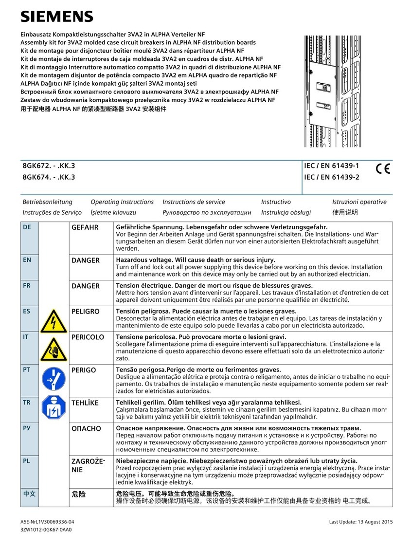
P5 Power Panel / Distribution
Switchboard High Density Kit
for Branch Mounting of
Type 3VA41 or xGB Breakers
Installation
Instructions
11-B-1058-01 Rev. 00
-4-
These instructions do not purport to cover all details or variations in equipment, or to provide for every possible
contingency to be met in connection with installation, operation or maintenance. Should further information be
desired or should particular problems arise, which are not covered sufficiently for the purchaser’s purposes, the
matter should be referred to the local Siemens sales office. The contents of this instruction manual shall not
become part of or modify any prior or existing agreement, commitment or relationship. The sales contract
contains the entire obligation of Siemens. The warranty contained in the contract between the parties is the sole
warranty of Siemens.
Any statements contained herein do not create new warranties or modify the existing warranty.
Trademarks - Unless otherwise noted, all names identified by ®are registered trademarks of Siemens AG or
Siemens Industry, Inc. The remaining trademarks in this publication may be trademarks whose use by third
parties for their own purposes could violate the rights of the owner.
S3VA41TDHD
11. Refer to Figure 7
If branch neutral terminal strips (Item 18) are
NOT already installed -- or are full -- then the
two branch neutral terminal strips (included, in
two bags labeled “Branch Neutral Lug Kit”) must
be installed. Depending upon the feed location,
the branch neutral can be mounted near the
bottom of the Z-rails -- or mirrored to the top --
on a branch neutral connector. Panelboards
should have one mounted already.
On Switch
boards, mount the branch neutral
connectors (Item 17) on the neutral bus using
(2) 1/4”-20 screws (Item 15) per connector, as
needed. Mount the neutral terminal strips
(Item 18) on either side of the branch neutral
connectors using (2) #8-32 screws
(Item 16) per
neutral strip. Torque all hardware as follows:
For 1/4”-20 screws, refer to torque on label.
For #8-32 screws, torque to 35 lb-in.
INSTALLING THE NEUTRAL COMPONENTS
13. Refer to Figure 8
Install the 7.5” cover plate (Item 7) by aligning
it over the 7.5” of selected unit space and
related breakers. Use two 1/4”-20 x 3/8” screw
(Item 14), one on each side of the cover plate, and
drive into the deadfront rails. Torque all hardware
as specified on the rear of the deadfront. Mark
the circuit ID cards (Item 8) as desired and
mount them to the cover plate by placing each
behind a clear card holder (Item 9) and pushing
the two into the proper pair of holes in the cover
plate next to the proper circuit. Repeat for each
location. Finally, use blank fillers (Item 10) at
every location that doesn’t have a breaker
penetrating through the cover plate.
NOTE: Other cover plates may be required for
proper fit. See filler plate kits listed on the rear
of the deadfront.
INSTALLING COVER PLATE
AND
FILLERS
14. Ensure that any bus or breaker hardware is
torqued as specified on the rear of the
deadfront.
Then replace all the cover plates
and gutter covers. Finally, ensure any fillers
are in place BEFORE re-energizing the
equipment.
COMPLETING THE INSTALLATION
Figure 7
PANELBOARD
REFERENCE
SWITCHBOARD
REFERENCE
12. Reassemble the deadfront assembly to the
interior (removed in Step 3).
18
17
15
16
18
16
S
8
9
10
14
7
Figure 8
(to
deadfront
rail)
(to
deadfront
rail)
Installation Instructions
The following instructions are for the installation of Siemens Type 3VA41 (SEAB, MEAB or HEAB) or
Type xGB (NGB, HGB or LGB) 2-pole breakers as branch devices in a Distribution Switchboard or
P5 Panelboard. The parts provided in this kit connect Type 3VA41 or xGB 2-pole breakers to a 3-phase, 3 or
4-wire system. It is for Type P5 (deep) or Distribution Switchboard installations. This kit requires 7.5” of unit
space.
NOTE: The breakers are NOT included in this kit and must be purchased separately.
11-B-1058-01 Rev. 00-3--2-
DANGER
Hazardous voltage.
Will cause death or
serious injury.
Keep out.
Qualified personnel only.
Disconnect and lock off all
power before working on
this equipment.
1. Lock off power supplying this equipment
before working on it.
6.
Refer to Figure 3
Locate a 0.228” diameter hole in the left Z-rail
1.88” below the top of the empty unit space
selected. Insert two 1/4”-20 x 3/8” screw (Item 14)
through the barrier support bracket (Item 5)
mounting holes and into the selected holes in the
Z-rail (orienting the bracket as shown). Repeat
this for the second mounting bracket onto the
right-side Z-rail. Tighten these four screws
(Item 14).
3. Refer to Figure 2
To mount a Siemens Type 3VA41 or xGB circuit
breaker,
7.5” of empty unit space is required.
To locate
the proper mounting position, measure
from the
top deadfront support to the intended
location of
the empty unit space (filler) on the
deadfront. Transfer this dimension from the
deadfront support along the Z-rail and mark.
This will be
the unit space (as shown in Figures
3 & 4). After
marking the Z-rail, remove the
deadfront rails.
4
.
If an existing branch module occupies the
same
location chosen for this kit, remove all of
its devices, components and parts.
INSTALLING THE RUNBACKS
7. Refer to Figure 4
Locate a 0.228” diameter hole in the A-phase
bus 1.25” down from the top of the 7.5” empty
unit space selected. Insert (2) 1/4”-20 screws (see
mounting hardware kit instructions located in Item
11
for the proper length) through the two mounting
holes in the A/C runback (Item 1) and into the (2)
selected holes in the A-phase bus (orienting the
A/C strap as shown) and tighten. Repeat this step
to mount the second runback to the C-phase bus,
this time 2.5” from the top. For the B-phase,
insert a 1/4”-20 screw (from Item 11) through the
mounting hole in the top B-phase runback (Item 3)
and
into the proper 0.228” hole located in the
B-phase
bus, 2.5” down from the top of the 7.5”
empty
unit space (orienting the B-phase runback as
shown) and tighten. Mount the second B-phase
runback (Item 3) in similar fashion, this time with the
1/4“-20 screw (Item 11) 1.25” from the bottom of the
7.5“ empty unit space.
Torque the 1/4”-20 screws
as specified on the rear of the deadfront.
INSTALLING THE MOUNTING BRACKETS
10. Refer to Figure 6 and Figure 6A
Orient the breaker so that the breaker stabs are
to the inside, and align the bottom of the Type
3VA41 or xGB breaker with the
top of the barrier.
Slide the breaker along until the
notch on the
bottom of the breaker fully engages the edge of
the barrier. Once fully engaged, use
#10-24 x 5/8” screws
(Item 13) to secure each of
the breaker pole stabs to the properly
aligned
straps. Torque all hardware as specified on the
rear of the deadfront.
INSTALLING THE SIEMENS BREAKER
9. Refer to Figure 5
To install the first B-phase strap (Item 4), locate it
in the center opening of the top barrier such that
the center hole lines up with
the mounting hole on
the top B-phase runback. Drive
a 1/4“-20 x 5/8”
screw (Item 15) thru the strap and
into the runback
and tighten. Repeat this for the other B-phase
strap to mount it to the lower barrier. For the
A & C-phase
straps (Item 2), take one and angle
the mounting side through the corresponding hole
in the barrier such that the strap mounting hole
aligns with the appropriate hole in the A-phase
runback.
Drive a 1/4”-20 x 5/8” screw (Item 15)
through the
strap and into the runback and tighten.
Similar, but opposite, for the C-phase strap. Then
repeat for the A / C-phase strap installation into
the other barrier. Torque the 1/4”-20 screws
as
specified on the rear of the deadfront.
INSTALLING THE STRAPS
2. Refer to Figure 1
Remove the gutter covers and cover plates.
5. Open the shipping box and inspect the contents.
Figure 6
THIS KIT CONTAINS THE FOLLOWING ITEMS:
**
Application dictates amount of these components used.
*** This sub-kit of parts is packaged in a bag labeled “Standard
Bus Hardware Kit”. It includes an instruction card and
Qty. 18 of fasteners (three different lengths). Select the
six required per the instruction card and discard the rest.
**** Required when used with Switchboard Distribution
application only.
ITEM
DESCRIPTION
QTY
1
2
3
4
5
6
7
8
9
10
Circuit ID Card
#10-24 x 5/8” Socket Head Cap Screw
Card Holder
B-phase Strap
B-phase Runback
A/C-phase Strap
7.5” Cover Plate 1
4
2
2
12
4
12
12
11
12
Barrier Support Bracket
1/4”-20 x 5/8” Hex Head Washer Screw ** 10
2
13
14
Blank Filler ** 12
15
16 #8-32 x 5/8” Hex Head Washer Screw
1/4”-20 x 3/8” Hex Head Washer Screw 6
4
#10-24 x 3/8” Hex Head Washer Screw
Bus Hardware Kit, Strap to Section *** 1
A/C-phase Runback 2
Top Barrier 2
Branch Neutral Connector **** 2
17
18 Branch Neutral Terminal Strip 2
Figure 1
Figure 2
COVER
PLATES
GUTTER
COVERS
Z-RAIL
DEADFRONT
SUPPORTS
DEADFRONT
RAIL
8. Refer to Figure 5
Set the top barriers (Item 6) over the two barrier
support brackets (Item 5) such that the barrier
mounting holes align with the holes on the brackets.
Insert a #10-24 x 3/8” screw (Item 12) on each
side of each barrier and tighten.
INSTALLING THE BARRIER
Figure 6a
BREAKER
NOTCH
ENGAGEMENT
6BREAKER
LINE STAB
BREAKER
BASE NOTCH
13
BREAKER
( 3VA41 shown )
Figure 3
Z-RAIL
7.5”
UNIT
SPACE
AØ
1.88” BØ CØ
5
14
3.12”
Figure 4
1.25” AØ BØ CØ
1
3
11
(Figure shows three-phase installation.)
7.5”
UNIT
SPACE
2.5”
1.25”
4.31”4.31”
Figure 5
3
15
6
2
4
13
15
12
8
9
10
14
7
(more instructions on following page)

Other Siemens Switch manuals

Siemens RUGGEDCOM RSG2488 User manual

Siemens

Siemens RUGGEDCOM RSG2488 User manual

Siemens SIMATIC NETRUGGEDCOM RS900W User manual

Siemens

Siemens SIMATIC NETRUGGEDCOM RS900W User manual

Siemens l-T-E MD6 User manual

Siemens

Siemens l-T-E MD6 User manual

Siemens SIMATIC NET RUGGEDCOM i801 User manual

Siemens

Siemens SIMATIC NET RUGGEDCOM i801 User manual

Siemens RUGGEDCOM RX1500 User manual

Siemens

Siemens RUGGEDCOM RX1500 User manual

Siemens SIMATIC NET RUGGEDCOM i802 User manual

Siemens

Siemens SIMATIC NET RUGGEDCOM i802 User manual

Siemens RUGGEDCOM RP110 User manual

Siemens

Siemens RUGGEDCOM RP110 User manual

Siemens Pointek CLS200 User manual

Siemens

Siemens Pointek CLS200 User manual

Siemens SCALANCE XP-200 User manual

Siemens

Siemens SCALANCE XP-200 User manual

Siemens 7XV75 User manual

Siemens

Siemens 7XV75 User manual

Siemens RUGGEDCOM RST2228 User manual

Siemens

Siemens RUGGEDCOM RST2228 User manual

Siemens SIMATIC NET RUGGEDCOM RS920W Technical Document

Siemens

Siemens SIMATIC NET RUGGEDCOM RS920W Technical Document

Siemens RUGGEDCOM RS416 User manual

Siemens

Siemens RUGGEDCOM RS416 User manual

Siemens SCALANCE XR-300M PoE Series Administrator guide

Siemens

Siemens SCALANCE XR-300M PoE Series Administrator guide

Siemens SIMATIC NET S7-1200 Administrator guide

Siemens

Siemens SIMATIC NET S7-1200 Administrator guide

Siemens SIRIUS 3SE53 Series User manual

Siemens

Siemens SIRIUS 3SE53 Series User manual

Siemens FDM243H User manual

Siemens

Siemens FDM243H User manual

Siemens SIRIUS 3RT2916-4MC00 User manual

Siemens

Siemens SIRIUS 3RT2916-4MC00 User manual

Siemens pointek CLS 100 User manual

Siemens

Siemens pointek CLS 100 User manual

Siemens RUGGEDCOM RSG908C Technical Document

Siemens

Siemens RUGGEDCOM RSG908C Technical Document

Siemens 3WX3684-1 Series User manual

Siemens

Siemens 3WX3684-1 Series User manual

Siemens Sirius 3RT1926-2E User manual

Siemens

Siemens Sirius 3RT1926-2E User manual

Siemens 7XV5550-0xA00 Series User manual

Siemens

Siemens 7XV5550-0xA00 Series User manual

Siemens SENTRON 3LD2 Series User manual

Siemens

Siemens SENTRON 3LD2 Series User manual

Popular Switch manuals by other brands

BEA MS31 Series quick start guide

BEA

BEA MS31 Series quick start guide

Dell S5048F-ON Firmware update

Dell

Dell S5048F-ON Firmware update

Roland v-1hd quick start guide

Roland

Roland v-1hd quick start guide

ATEN MASTER VIEW CS-92 user manual

ATEN

ATEN MASTER VIEW CS-92 user manual

H3C S1200 Series Getting started guide

H3C

H3C S1200 Series Getting started guide

Potter PS10 Series manual

Potter

Potter PS10 Series manual

Texas Instruments XIO3130 EVM user guide

Texas Instruments

Texas Instruments XIO3130 EVM user guide

cable matters 103075 - 3 Port user manual

cable matters

cable matters 103075 - 3 Port user manual

Cisco WS-C2950SX-48-SI Configuration guide

Cisco

Cisco WS-C2950SX-48-SI Configuration guide

OFFICINE OROBICHE 10 Series instruction manual

OFFICINE OROBICHE

OFFICINE OROBICHE 10 Series instruction manual

Rotronic 14.99.3565 quick start guide

Rotronic

Rotronic 14.99.3565 quick start guide

JVC JX-S333-J instructions

JVC

JVC JX-S333-J instructions

TJERNLUND 950-0452 PAI-1,2 PROVER KIT 8504044 REV. 1... manual

TJERNLUND

TJERNLUND 950-0452 PAI-1,2 PROVER KIT 8504044 REV. 1... manual

KTI Networks KS-115F Series installation guide

KTI Networks

KTI Networks KS-115F Series installation guide

ABB TL Series installation manual

ABB

ABB TL Series installation manual

Emerson Rosemount 2410 instruction manual

Emerson

Emerson Rosemount 2410 instruction manual

Cisco WS-C3550-12G datasheet

Cisco

Cisco WS-C3550-12G datasheet

SMC Networks TigerSwitch 100 Management guide

SMC Networks

SMC Networks TigerSwitch 100 Management guide

manuals.online logo
manuals.online logoBrands
  • About & Mission
  • Contact us
  • Privacy Policy
  • Terms and Conditions

Copyright 2025 Manuals.Online. All Rights Reserved.