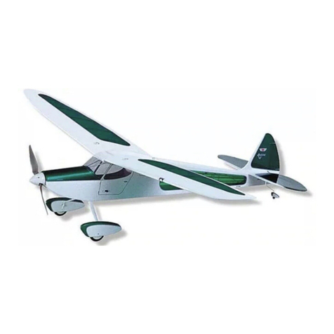
SIG SIGRC44 User manual


This manual suits for next models
1
Table of contents
Other SIG Toy manuals

SIG
SIG KADET LT-25 User manual

SIG
SIG HERR FAIRCHILD 24 User manual
SIG
SIG Kadet Senorita EP User manual

SIG
SIG RASCAL FORTY User manual
SIG
SIG Sigrc47 Instruction Manual

SIG
SIG King Kobra Instruction Manual
SIG
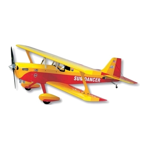
SIG Sun Dancer User manual
SIG
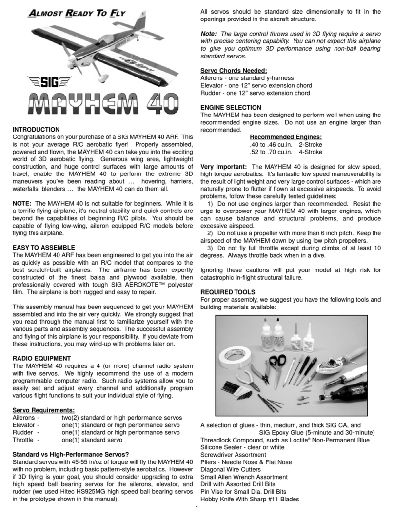
SIG MAYHEM 40 User manual
SIG
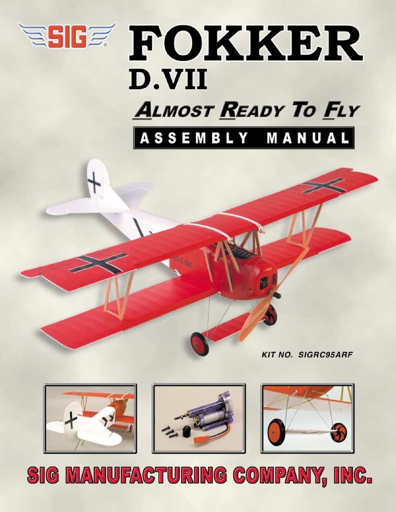
SIG SIGRC95ARF Fokker D.VII User manual
SIG
SIG CAP 231EX User manual
SIG
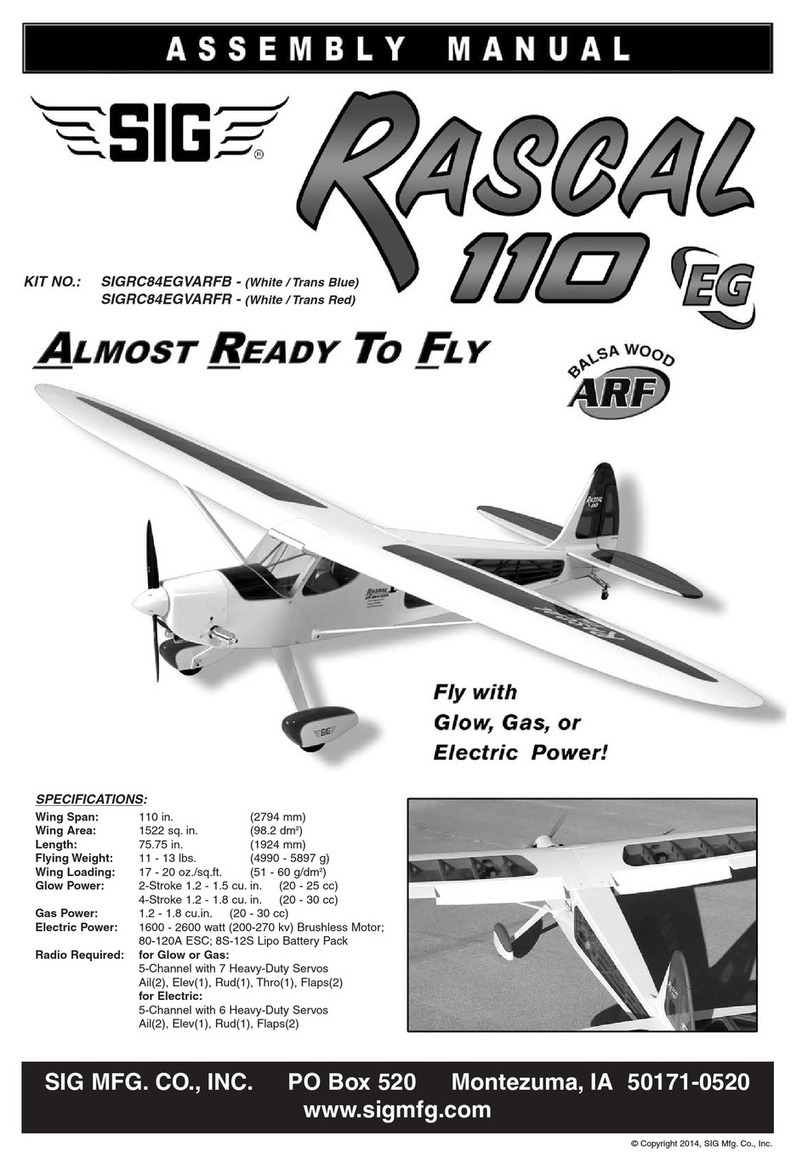
SIG RASCAL 110 EG ARF User manual
SIG
SIG Kadet Senior User manual
SIG
SIG Four-Star 120 Instruction Manual

SIG
SIG FOUR-STAR 60 User manual
SIG
SIG Kougar MARK II SIGRC35 Instruction Manual
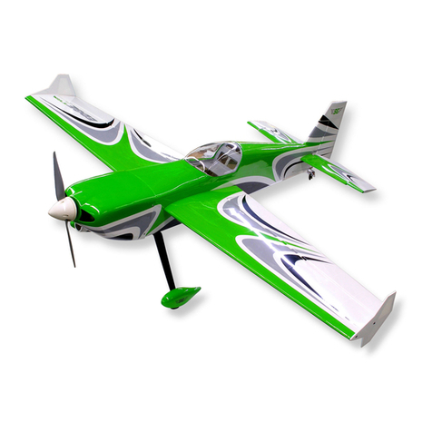
SIG
SIG Edgetra ARF User manual
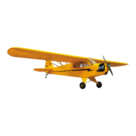
SIG
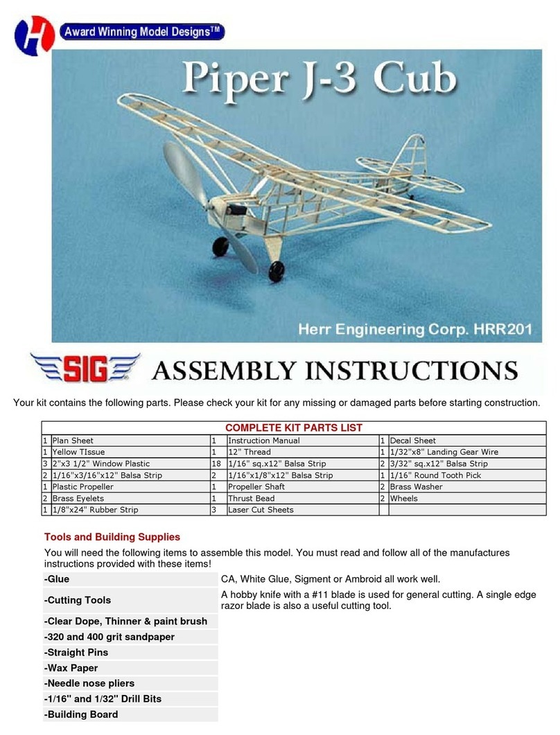
SIG Piper J3 Cub Instruction Manual

SIG
SIG Somethin' EXTRA N477SC User manual
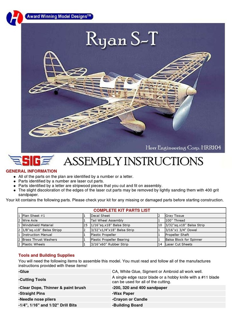
SIG
SIG Ryan S-T Datasheet
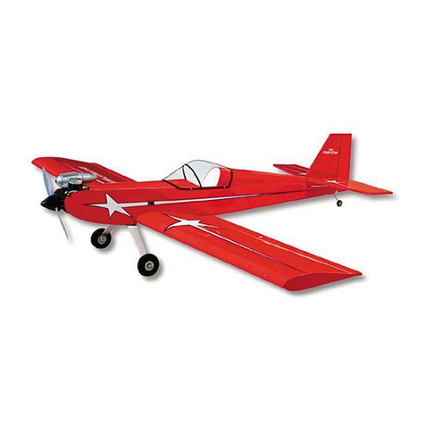
SIG
SIG 4-STAR 60 Instruction Manual
Popular Toy manuals by other brands

Eduard
Eduard Zoom F-35A seatbelts STEEL 1/32 quick start guide
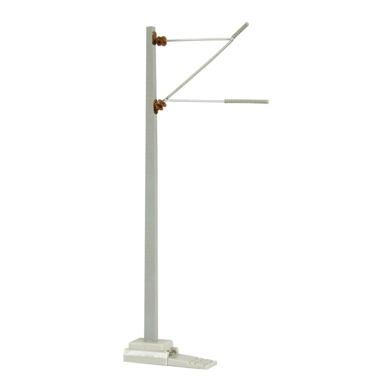
Viessmann
Viessmann 4101 Operation manual
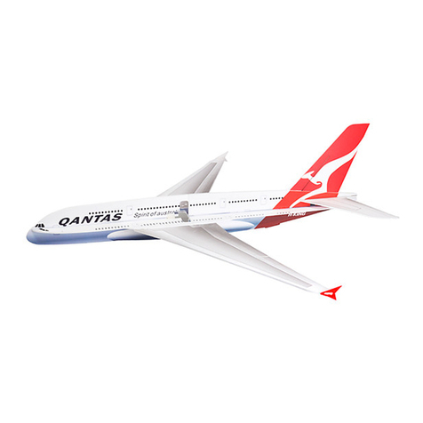
H-KING
H-KING Glue-N-Go A380 PP Kit instruction manual
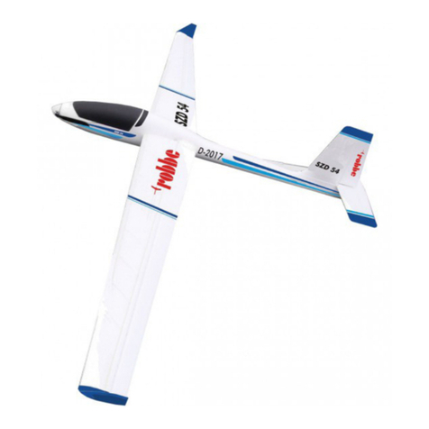
ROBBE
ROBBE SZD-54 operating instructions

Fisher-Price
Fisher-Price Rescue Heroes 72955 instructions
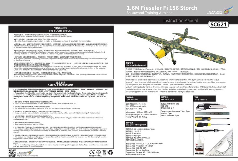
Dancing Wings Hobby
Dancing Wings Hobby SCG21 instruction manual

LEGO
LEGO NINJAGO 70682 manual
Revell Control
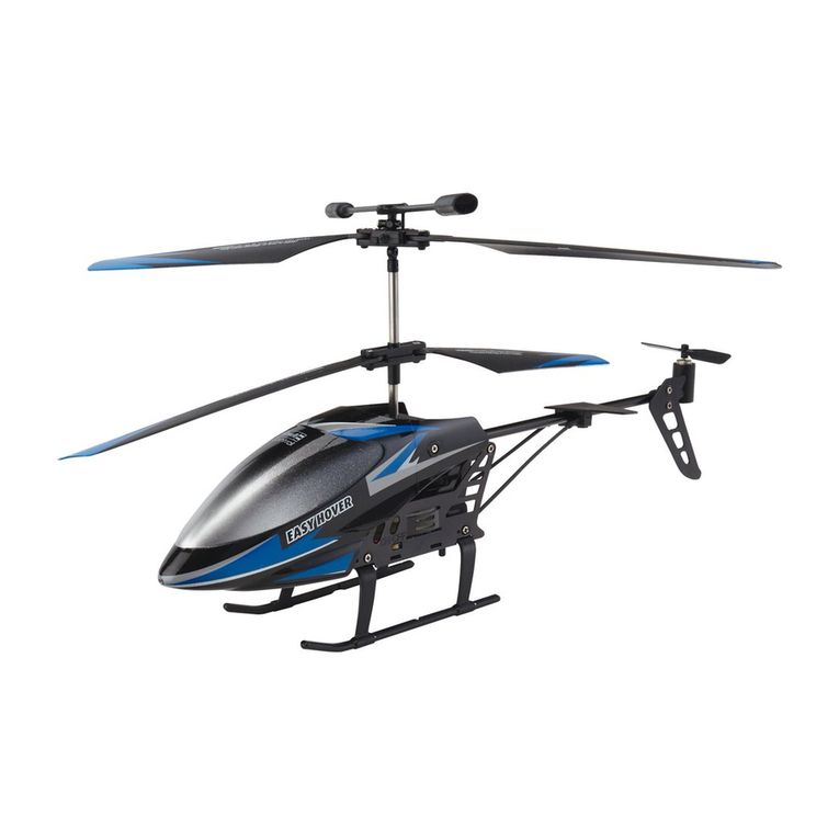
Revell Control Easy Hover 23864 user manual

Fisher-Price
Fisher-Price R9698 owner's manual

Eduard
Eduard Pz.Kpfw III Ausf.M track manual

Black Horse Model
Black Horse Model SPITFIRE MX Instruction manual book
Phoenix Model
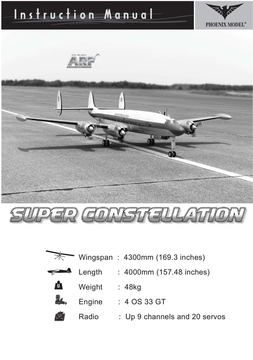
Phoenix Model super constellation instruction manual
