SIGMA TEK C-IPC 171 User manual

C-IPC 171
C-DIAS IPC
with AMD Fusion G-T56N
Date of creation: 27.07.2017
Version date: 04.11.2019
Article number: 01-450-171-E

Publisher: SIGMATEK GmbH & Co KG
A-5112 Lamprechtshausen
Tel.: +43/6274/4321
Fax: +43/6274/4321-18
WWW.SIGMATEK-AUTOMATION.COM
Copyright © 2017
SIGMATEK GmbH & Co KG
Translation from German
All rights reserved. No part of this work may be reproduced, edited using an electronic system, duplicated or dis-
tributed in any form (print, photocopy, microfilm or in any other process) without the express permission.
We reserve the right to make changes in the content without notice. The SIGMATEK GmbH & Co KG is not responsi-
ble for technical or printing errors in the handbook and assumes no responsibility for damages that occur through
use of this handbook.

C-DIAS IPC WITH AMD FUSION G-T56N C-IPC 171
04.11.2019 Page 1
C-DIAS IPC with AMD Fusion G-T56N C-IPC 171
Compact DIAS
Industrial
Personal
Computer
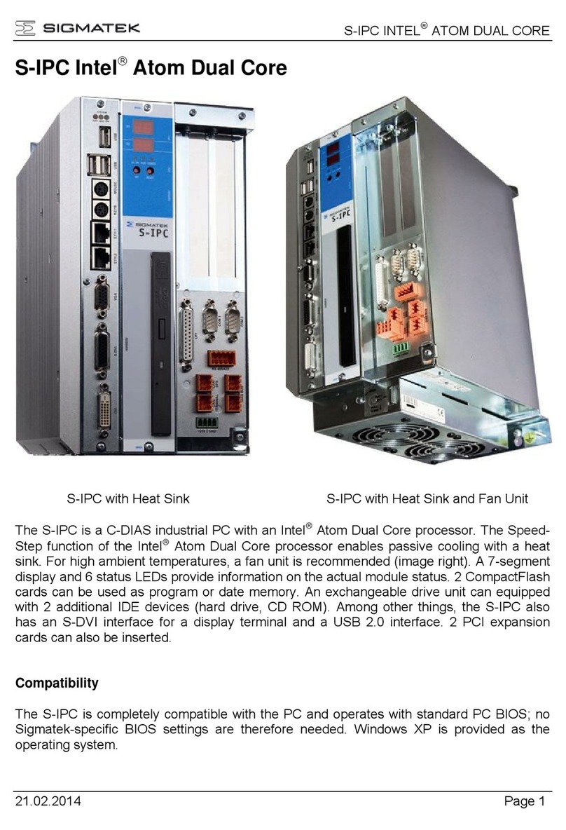
The C-IPC is a C-DIAS industrial PC with
an AMD Fusion processor. A 7-segment
display and 3 status LEDs provide infor-
mation on the actual status of the CPU.
A CompactFlash card can be used as
program memory. The C-IPC also has an
VGA interface for a display and a USB
V1.1 interface. In addition, an expansion
card with further interface connections is
available.
Compatibility
Completely PC-compatible. The C-IPC works with a standard PC BIOS; no SIGMATEK-
specific BIOS is therefore needed. LASAL is provided as the operating system.

C-IPC 171 C-DIAS IPC WITH AMD FUSION G-T56N
Page 2 04.11.2019
Contents
1Technical Data ........................................................................ 4
1.1 Performance Data.........................................................................4
1.2 Standard Configuration................................................................5
1.3 Electrical Requirements...............................................................5
1.4 Miscellaneous ...............................................................................6
1.5 Environmental Conditions...........................................................6
1.6 Xilinx Version................................................................................7
1.7 Post Codes....................................................................................7
2Mechanical Dimensions......................................................... 8
3Connector Layout................................................................... 9
3.1 Connector Layout.......................................................................10
3.2 Applicable Connectors...............................................................13
3.3 Bottom Connectors ....................................................................14
4Status Displays......................................................................15
5Setting C-IPC Parameters with the SET Button (under
LASAL operating system only).............................................16
6Design Layout........................................................................19
6.1 Exchanging the CompactFlash Card........................................22
6.2 Storage Media .............................................................................23
6.3 Exchanging the Battery..............................................................24

C-DIAS IPC WITH AMD FUSION G-T56N C-IPC 171
04.11.2019 Page 3
6.4 CAN Bus Termination.................................................................25
6.5 RS485...........................................................................................26
6.6 USB Interface Connections .......................................................27
6.7 DIAS Bus Termination................................................................27
6.8 The DIAS Bus Connection .........................................................27
6.9 Connecting DIAS Modules.........................................................29
7Buffer Battery ........................................................................30
8Cooling...................................................................................31
9System Boot Checkpoints....................................................31
10 Status and Error Messages..................................................32

C-IPC 171 C-DIAS IPC WITH AMD FUSION G-T56N
Page 4 04.11.2019
1 Technical Data
1.1 Performance Data
Processor
AMD G-T56N Dual Core 1.65GHz
Internal program memory
(CompactFlash)
1x Compact Flash (1x 512-MByte card)
Internal program memory (SRAM)
256 Kbytes (battery powered)
Internal program memory (DDR-RAM)
1 GB DDR3-RAM
Interfaces
1x x Ethernet 10/100 Mbit
1x RS 232 –COM1
1x RS232/ RS485/ RS422 –COM2
1x DIAS intelligent (Weidmüller plug and 14-Pin ribbon cable)
1x CAN for PLC
1x CAN for a Terminal
1x VGA
1x S-DVI interface for a 15” terminal (TFT display, USB, CAN key-
board)
Resolution 1024 x 768 pixels
1x USV
1x USB V1.1
Interfaces via expansion cards (optional):
1x VARAN (maximum cable length: 100 m)
1x Ethernet 10/100
1x LPT –Printer
1x RS232/ RS485/ RS422 –COM3
1x RS232/ RS485/ TTY/ Multi-drop Bus - COM4
Data buffer
Buffered via lithium battery
Status display
yes
Status LEDs
yes
Real-time clock
yes

C-DIAS IPC WITH AMD FUSION G-T56N C-IPC 171
04.11.2019 Page 5
1.2 Standard Configuration
Ethernet
IP 10.10.150.1
Subnet mask: 255.0.0.0
CAN bus PLC
Station: 00
Baud rate: 00 = 615 kBaud
CAN bus Terminal
Station: 00
Baud rate: 00 = 615 kBaud
COM 1 (RS232)
57600 Baud
COM 2 (RS232)
57600 Baud
The CAN bus terminal is initialized by the FPGA and is limited in use!
Several CAN objects of the CAN bus terminal are not available.
Problems can arise if a control is connected to an IP network, which contains mod-
ules that do not run on a SIGMATEK operating system. With such devices, Ethernet
packets could be sent to the control with such a high frequency (i.e. broadcasts), that
the high interrupt load could cause a real-time runtime error or runtime error. By
configuring the packet filter (Firewall or Router) accordingly however, it is possible
to connect a network with SIGMATEK hardware to a third-party network without trig-
gering the error mentioned above.
1.3 Electrical Requirements
Supply voltage
18-30 V DC (1), typically +24 V DC UL: Class 2 or LVLC (3)
Current consumption
of the power supply (24 V)
maximum 3,2 A (depending on external devices)
Inrush current
maximum 9 A for ~17 ms (2)
Available current for DIAS (+5 V)
maximum 1 A
Available current for C-DIAS (+5 V)
maximum 1.2 A
(1) For a supply voltage between 18-22 V, it is buffered for only 3 ms.
(2) Measured with a 24 V/10 A fixed voltage supply. If a power supply over 10 A is used an increased inrush current
can result.
(3) For USA and Canada:
The supply must be limited to:
a) max. 5 A at voltages from 0-20 V DC, or
b) 100 W at voltages from 20-60 V DC
The limiting component (e.g. transformer, power supply or fuse) must be certified by an
NRTL (Nationally Recognized Testing Laboratory).

C-IPC 171 C-DIAS IPC WITH AMD FUSION G-T56N
Page 6 04.11.2019
(3) Pour les États-Unis et le Canada:
L’alimentation doit être limitée à:
a) max. 5 A pour des tensions de 0-20 V DC, ou
b) 100 W pour des tensions de 20-60 V DC
Le composant imposant la limite (par exemple, transformateur, alimentation électrique ou
fusible) doit être certifié par un NRTL (National Recognized Testing Laboratory, par exem-
ple, UL).
1.4 Miscellaneous
Article number
C-IPC 171 1 GB Fusion T56N
1 GB DDR3-RAM, 1x 512 MB CompactFlash 01-450-171
TC-IPC 171 1 GB Fusion T56N
1 GB DDR3-RAM, 1x 512 MB CompactFlash
with Coating of the electronic 01-450-171-T
Module identification on DIAS bus
no
Hardware Version
1.x
Project backup
internally on CompactFlash
Standard
UL 508 (E247993)
Approvals
CULUS listed, CE
1.5 Environmental Conditions
Storage temperature
-20 ... +85 °C
Ambient temperature
+5 ... +50 °C
Max. Process temperature
+125 °C (automatic cut-off)
Humidity
0-95 %, non-condensing
EMC resistance
in accordance with EN 61000-6-2 (industrial area)
EMC noise generation
in accordance with EN 61000-6-4 (industrial area)
Shock resistance
EN 60068-2-27
150 m/s²
Protection type
EN 60529
IP20

C-DIAS IPC WITH AMD FUSION G-T56N C-IPC 171
04.11.2019 Page 7
1.6 Xilinx Version
Directly after the C-IPC is turned on, the Xilinx version number is shown in the display.
In display D1, 43 is shown and in display 41, the version number can be seen. This infor-
mation can also be found on the identification label. (e.g.: X 1.8)
1.7 Post Codes
During startup, the BIOS-dependent post codes are shown in the display It is important to
note these codes in order to simplify troubleshooting if an error occurs.

C-IPC 171 C-DIAS IPC WITH AMD FUSION G-T56N
Page 8 04.11.2019
2 Mechanical Dimensions

C-DIAS IPC WITH AMD FUSION G-T56N C-IPC 171
04.11.2019 Page 9
3 Connector Layout

C-IPC 171 C-DIAS IPC WITH AMD FUSION G-T56N
Page 10 04.11.2019
3.1 Connector Layout
X1 COM 1 (10-pin Weidmüller plug)
X2 COM 2 (10-pin Weidmüller plug)
X3 CAN Bus PLC (6-pin Weidmüller plug)
Pin
Function
1
RxD
2
RTS
3
TxD
4
CTS
5
DTR
6
GND
7
DCD
8
DSR
9
RI
10
n.c.
Pin
Function RS232
Function RS422
Function RS485
1
RxD
RS422 TxD+
RS485 A
2
RTS
RS422 TxD-
RS485 B
3
TxD
RS422 RxD+
n.c.
4
CTS
RS422 RxD-
n.c.
5
DTR
n.c.
n.c.
6
GND
GND
GND
7
n.c.
RS422 TxD+
RS485 A
8
n.c.
RS422 TxD-
RS485 B
9
n.c.
RS422 RxD+
n.c.
10
n.c.
RS422 RxD-
n.c.
Pin
Function
1
CAN SA = LOW
2
CAN SB = HIGH
3
CAN SA = LOW
4
CAN SB = HIGH
5
GND
6
+5 V (for online adapter)

C-DIAS IPC WITH AMD FUSION G-T56N C-IPC 171
04.11.2019 Page 11
X4 CAN Bus Terminal (6-pin Weidmüller plug)
X5 DIAS Bus (6-pin Weidmüller plug)
X6 USB (Type A)
X7 S-DVI (26-pin HD-DSUB)
Only 15” TAE models can be driven on the S-DVI interface of this PC.
Pin
Function
1
CAN A = LOW
2
CAN B = HIGH
3
CAN A = LOW
4
CAN B = HIGH
5
GND
6
n.c.
Pin
Function
1
MBUS+
2
MBUS-
3
SBUS+
4
SBUS-
5
GND
6
n.c.
Pin
Function
1
+5 V
2
D0-
3
D0+
4
GND
Pin
Function
Pin
Function
1
DVI1+
14
Shielded
2
DVI1
15
Shielded
3
DVI2+
16
Shielded
4
DVI2
17
Shielded
5
DVI3+
18
Shielded
6
DVI3
19
+24 V
7
DVIC+
20
+24 V
8
DVIC-
21
USB Ext. In+
9
Reserved
22
USB Ext. In-
10
GND
23
USB Ext. Out+
11
GND
24
USB Ext. Out-
12
Shielded
25
CAN A
13
Shielded
26
CAN B

C-IPC 171 C-DIAS IPC WITH AMD FUSION G-T56N
Page 12 04.11.2019
X8 Ethernet (8-pin RJ45)
8 1
X9 Video (RGB)
For using the X9 video output, it is necessary to either connect a display before the
C-IPC is started or restart the C-IPC after a display has been connected. Otherwise a
video signal will not be sent to this interface.
X10 Power Supply 24 - 30 Volt DC
2-pin Phoenix 3.5 mm (power supply)
X11 External UPS Connection
6-pin Phoenix 3.5 mm (UPS)
Pin
Function
1
TD+
2
TD-
3
RD+
4
n.c.
5
n.c.
6
RD-
7
n.c.
8
n.c.
Pin
Function
1
red
2
GND
3
green
4
GND
5
blue
6
GND
7
Vsync
8
GND
9
Hsync
10
GND
Pin
Function
1
+24 V
2
GND
Pin
Function
1
RxD
2
TxD
3
RTS (USV Off)
4
CTS (+24 V OK)
5
DCD (Battery weak)
6
GND
1
1

C-DIAS IPC WITH AMD FUSION G-T56N C-IPC 171
04.11.2019 Page 13
3.2 Applicable Connectors
COM1/COM2: 10-pin Weidmüller plug B2L3, 5/10
CAN/ DIAS bus: 6-pin Weidmüller connector plug B2L3, 5/6
USB: Type A
Ethernet: 8-pin RJ 45
Video: 10-pin RM 2.54
Power: 2-pin Phoenix FK-MCP 1.5/2-ST-3.5
USV: 6-pin Phoenix FK-MCP 1.5/6-ST-3.5
The complete C-DIAS CKL 012 connector set with spring terminals is available from
SIGMATEK under the article number 12-600-012.
S-DVI Cable
0.3 m
2 m
3 m
3.5
5 m
7 m
10 m
15 m
Art.No.: 05-950-003
Art.No.: 05-950-020
Art.No.: 05-950-030
Art.No.: 05-950-035
Art.No.: 05-950-050
Art.No.: 05-950-070
Art.No.: 05-950-100
Art.No.: 05-950-150
NOTE:
Connecting the S-DVI cable under voltage can damage the S-DVI interface; it is not
hot-plug capable.

C-IPC 171 C-DIAS IPC WITH AMD FUSION G-T56N
Page 14 04.11.2019
3.3 Bottom Connectors
X12 C-DIAS Bus Connector
16 1
c
b
a
X13 DIAS Bus Connector
1
14
CAUTION!
To connect the DIAS module to X13 of the C-IPC, a DIAS power module (power booster)
between the C-IPC and DIAS module is required. The measure is necessary to protect the
C-IPC from EMC-noise and to unburden the DCDC converter in the C-IPC (reducing power
loss in the C-IPC).
Pin
Function
1
GND
2
MBUS+
3
MBUS-
4
GND
5
SBUS+
6
SBUS-
7
GND
8
DCOK
9 –13:
+5 V
14
GND
Connection to the C-
IPC (X13)
Connection to the 1st
DIAS module
DPB 002
05-002-002l

C-DIAS IPC WITH AMD FUSION G-T56N C-IPC 171
04.11.2019 Page 15
4 Status Displays
LED 1
Green
DC OK
Lights when the supply voltage is correct.
LED 2
Green
Run
Lights when the program is running
LED 3
Red
Error
Lights when an error occurs
Button 1
Set
Set/display Ethernet, CAN address
Button 2
Reset
Reset CPU hardware

C-IPC 171 C-DIAS IPC WITH AMD FUSION G-T56N
Page 16 04.11.2019
5 Setting C-IPC Parameters with the SET Button
(under LASAL operating system only)
To enter the mode to change settings, press and hold the SET button while the C-IPC is
booting
When the following display appears
The SET button can be released.
The upper section of the display shows which setting can be changed; the lower section of
the display shows the set value.
The blinking part of the display can be set with a short press of the SET button:
If the upper section is blinking, the various settings can be viewed by quickly pressing the
set button multiple times. To change between the setting and the value, the Set button must
be pressed for about 1.5 s.
Once the desired changes are made, press the SET button for about 5 seconds to end the
process. If the changes are to be discarded, press the RESET button to restart the C-IPC
The settings for the IP address, subnet mask and gateway are hexadecimal, whereas in the
left and right digits, 0 - F must be entered separately. The changeover is triggered by press-
ing the SET button for about 1.5 s
The values from AUTOEXEC.LSL are used as the standard settings; changes are written
back to this file. Before this, the original content of the file is written to AUTOEXEC.BAK.

C-DIAS IPC WITH AMD FUSION G-T56N C-IPC 171
04.11.2019 Page 17
Gr ... graphics resolution
01 ... QVGA 320x240
02 ... VGA 640x480
03 ... SVGA 800x600
04 … XGA 1024x768
L1 … Lasal Online COMx interface number
01 ... COM1
02 ... COM2
L2 .. Lasal Online Baud rate for COMx
00 ... 300
01 ... 600
02 ... 1200
03 ... 2400
04 ... 4800
05 ... 9600
06 ... 14400
07 ... 19200
08 ... 38400
09 ... 57600
10 ... 115200
C1 ... CAN PLC station
00 –30 ... Station number
C2 ... CAN PLC baud rate
00 ... 615.000
01 … 500,000
02 … 250,000
03 … 125,000
04 … 100,000
05 … 50,000
06 … 20,000
07 … 1,000,000

C-IPC 171 C-DIAS IPC WITH AMD FUSION G-T56N
Page 18 04.11.2019
I1, I2, I3, I4 IP Address I1.I2.I3.I4, hexadecimal
00-FF respectively
S1, S2 ,SI3, S4 Subnet Mask SI1SI2.S3.S4, hexadecimal
00-FF respectively
G1, G2, G3, G4 Gateway G1,G2.G3.G4, hexadecimal
00-FF respectively
Table of contents
Other SIGMA TEK Industrial PC manuals
Popular Industrial PC manuals by other brands

Matrox
Matrox 4Sight EV6 Installation and Hardware Reference

Aplex
Aplex AHMI-8 Series user manual

Moxa Technologies
Moxa Technologies IA3341 Quick installation guide

AXIOMTEK
AXIOMTEK eBOX670-883-FL Series Quick installation guide

Beckhoff
Beckhoff C6025 manual

Acrosser Technology
Acrosser Technology AR-V5430FL installation guide