Signet 8550-1 User manual
page 1 of 8‡ SIGNET 8550-1 Flow Transmitter
CAUTION!
• Remove power to unit before wiring
input and output connections.
• Follow instructions carefully to avoid
personal in ury.
‡ SIGNET 8550-1 Flow Transmitter ENGLISH
Contents
1. Installation
2. Specifications
3. Electrical Connections
4. Menu Functions
• Max loop impedance: 50 Ω max. @ 12 V
325 Ω max. @ 18 V
600 Ω max. @ 24V
• Update rate: 100 ms
• Accuracy: ±0.03 mA
Open-collector output, optically isolated:
• 50 mA max. sink, 30 VDC maximum pull-up voltage.
• Programmable for:
• High or Low setpoint with ad ustable hysteresis
• Pulse operation (max rate: 300 pulses/min).
En ironmental
• Operating temperature: -10 to 70°C (14 to 158°F)
• Storage temperature: -15 to 80°C (5 to 176°F)
• Relative humidity: 0 to 95%, non-condensing
• Maximum altitude: 2000 m (6562 ft)
• Insulation category: II
• Pollution degree: 2
Standards and Appro als
• CSA, CE, UL listed
• Immunity: EN50082-2
• Emissions: EN55011
• Safety: EN61010
• Manufactured under ISO 9001 and ISO 14001
2 . Specifications
General
Compatibility: +GF+ SIGNET Flow Sensors (w/freq out)
Accuracy: ±0.5 Hz
Enclosure:
• Rating: NEMA 4X/IP65 front
• Case: PBT
• Panel case gasket: Neoprene
• Window: Polyurethane coated polycarbonate
• Keypad: Sealed 4-key silicone rubber
• Weight: Approx. 325g (12 oz.)
Display:
• Alphanumeric 2 x 16 LCD
• Update rate: 1 second
• Contrast: User selected, 5 levels
Electrical
• Power: 12 to 24 VDC ±10%, regulated, 61 mA max current
Sensor Input:
• Range: 0.5 to 1500 Hz
• Sensor power: 2-wire: 1.5 mA @ 5 VDC ± 1%
3 or 4 wire: 20 mA @ 5 VDC ± 1%
• Optically isolated from current loop
• Short circuit protected
Current output:
• 4 to 20 mA, isolated, fully ad ustable and reversible
Flow
Flow 6.25 GPM
Total 1234567.8>
ENTER
3-8550.090-1
1. Installation
ProcessPro transmitters are available in two styles: panel mount and field mount. The panel mount is supplied with the necessary
hardware to install the transmitter. This manual includes complete panel mounting instructions.
Field mounting requires one of two separate mounting kits. The 3-8051 integral kit oins the sensor and instrument together into a
single package. The 3-8050 Universal kit enables the transmitter to be installed virtually anywhere.
Detailed instructions for integral mounting or other field installation options are included with the 3-8051 Integral kit or the 3-8050
Universal kit.
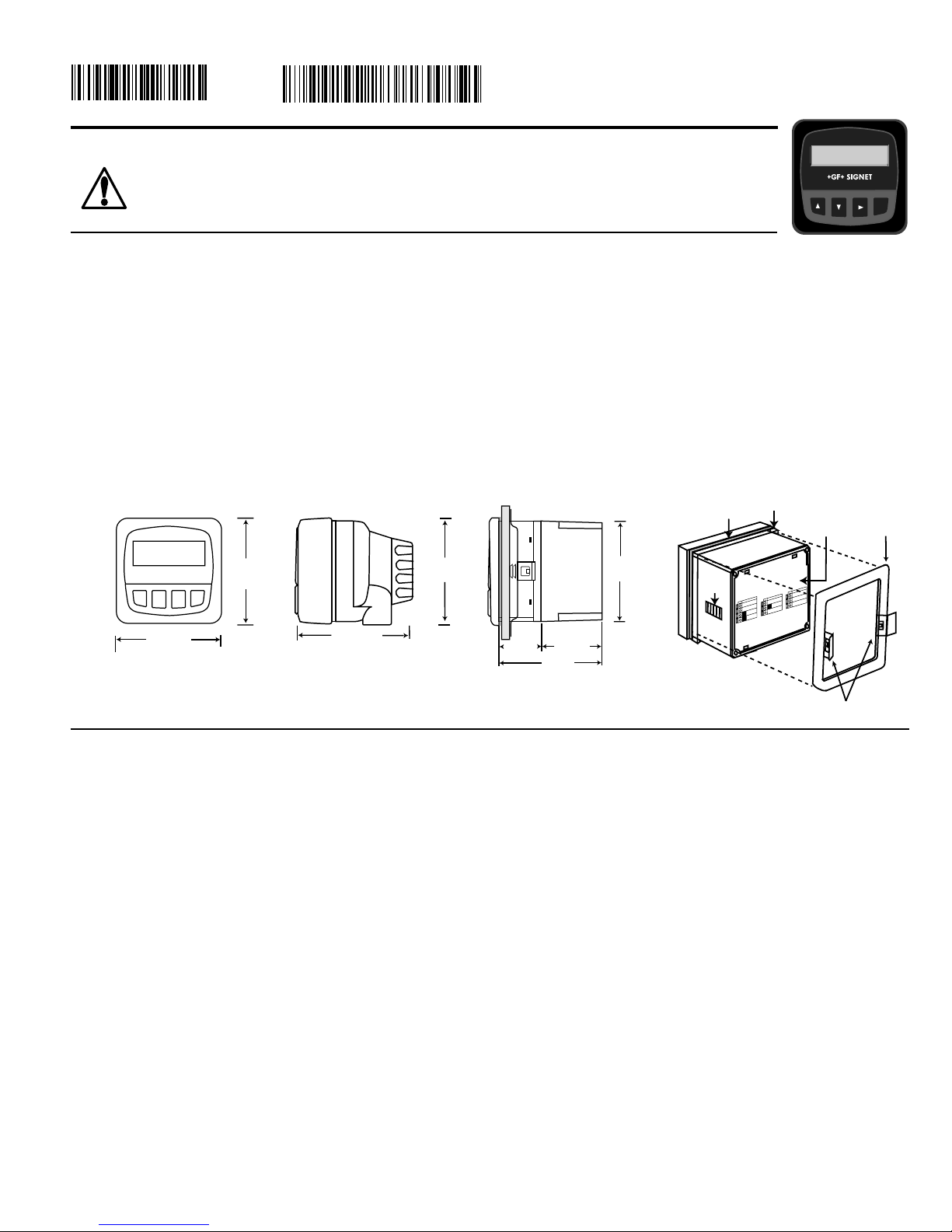
1.1 Panel Installation
1. The panel mount transmitter is designed for installation using a 1/4 DIN Punch. For manual panel cutout, an adhesive
template is provided as an installation guide. Recommended clearance on all sides between instruments is 1 inch.
2. Place gasket on instrument, and install in panel.
3. Slide mounting bracket over back of instrument until quick-clips snap into latches on side of instrument.
4. To remove, secure instrument temporarily with tape from front or grip from rear of instrument. DO NOT RELEASE.
Press quick-clips outward and remove.
SIDE VIEW
92 mm
(3.6 in.)
97 mm
(3.8 in.)
56 mm
(2.2 in.)
41 mm
(1.6 in.
)
Optional
Rear
Cover
Field Mount Panel Mount
FRONT VIEW
96 mm
(3.8 in.)
96 mm
(3.8 in.)
102 mm
(4.0 in.)
96 mm
(3.8 in.)
quick-clips
gasket panel
terminals mounting
bracket
latch
Output -
Output +
System Pwr
Loop -
System Pwr
Loop +
2
14
3
Sensr Gnd
(SHIELD)
Sensr IN
(RED)
Sensr V+
(BLACK)
7
6
5
SIDE VIEW
Field Mount &
Panel Mount
Panel Mount
Installation Detail
C-3/01 English

page 2 of 8 ‡ SIGNET 8550-1 Flow Transmitter
Output -
Output +
System Pwr
Loop -
System Pwr
Loop +
AUX
Power -
AUX
Power +
4
3
2
1
6
5
Sensr Gnd
(SHIELD)
Sensr IN
(RED)
Sensr V+
(BLACK)
9
8
7
3. Electrical Connections
Caution: Failure to fully open terminal aws before removing wire may permanently damage instrument.
Wiring Procedure
1. Remove 0.5 - 0.625 in. (13-16 mm) of insulation from wire end.
2. Press the orange terminal lever downward with a small screwdriver to open terminal aws.
3. Insert exposed (non-insulated) wire end in terminal hole until it bottoms out.
4. Release orange terminal lever to secure wire in place. Gently pull on each wire to ensure a good connection.
Wiring Removal Procedure
1. Press the orange terminal lever downward with a small screwdriver to open terminal aws.
2. When fully open, remove wire from terminal.
2
1
Terminals 5 and 6: Open-collector Output
A transistor output, programmable (see CALIBRATE menu) as:
• High or Low setpoint with ad ustable hysteresis
• Volumetric pulse
• Frequency based on flow rate
• May be disabled (Off) if not used.
Terminals 3 and 4: Loop Power
12-24 VDC ±10% system power
and current loop output.
Max. loop impedance:
50 Ω max. @ 12 V
325 Ω max. @ 18 V
600 Ω max. @ 24 V
Terminals 7-9: Flow sensor input
Internal open-collector
output circuit
Output --
Output +
Isolation
15Ω
S
D
Terminals 1 and 2: AUXILIARY power
Used only if the flow sensor requires
more than 1.5 mA current. For Signet
sensors this is limited to the following
products:
• 2000 • 2507
• 2530 • 2535
• 2540 if mfg. prior to Jan 1999

page 3 of 8‡ SIGNET 8550-1 Flow Transmitter
3.1 System Power/Loop Connections
3.2 Sensor Input Connections
Wiring Tips:
• Do not route sensor cable in conduit containing AC power wiring. Electrical noise may interfere with sensor signal.
• Routing sensor cable in grounded metal conduit will help prevent electrical noise and mechanical damage.
• Seal cable entry points to prevent moisture damage.
• Only one wire should be inserted into a terminal. Splice double wires outside the terminal.
Transmitter
≤ 200 ft. (61 m)
Transmitter
≤ 1000 ft. (300 m)
Maximum cable length is 200 ft. for 515/8510-XX, 525 , 2517 and
any sinusoidal flow signal.
Maximum cable length is 1000 ft. for 2536/8512-XX, 2540, vortex,
and any square wave flow signal.
Stand-alone application, no current loop used
Transmitter
Terminals
4
3
2
1
Sys. Pwr.
Loop -
Sys. Pwr.
Loop +
AUX
Power -
AUX
Power +
Power Supply
DC 12 - 24 V
Power
Supply
Power
Supply
Connection to a PLC with built-in power supply
PLC
Terminals
Power Supply
Ground
Power
Supply
Loop Input
4-20 mA
Loop Input
4-20 mA
Internal PLC
Connection
Connection to a PLC/Recorder, separate supply
PLC or Recorder
Loop Input
4-20 mA in
Loop Input
4-20 mA in
DC 12 - 24 V
Power
Supply
Power
Supply
Example: Two transmitters connected to PLC/Recorder
with separate power supply
Transmitter 2
4
3
2
1
DC 12 - 24 V
Power
Supply
Power
Supply
Transmitter 1
4
3
2
1
Transmitter
Terminals
4
3
2
1
Sys. Pwr.
Loop -
Sys. Pwr.
Loop +
AUX
Power -
AUX
Power +
Transmitter
Terminals
4
3
2
1
Sys. Pwr.
Loop -
Sys. Pwr.
Loop +
AUX
Power -
AUX
Power +
Sys. Pwr.
Loop -
Sys. Pwr.
Loop +
AUX
Power -
AUX
Power +
Sys. Pwr.
Loop -
Sys. Pwr.
Loop +
AUX
Power -
AUX
Power +
PLC or Recorder
Channel 1
4-20 mA in
Channel 1
4-20 mA in
Channel 2
4-20 mA in
Channel 2
4-20 mA in
* See AUX POWER Note
* See AUX POWER Note
* See AUX POWER Note
* See AUX POWER Note
-
+
-
+
-
+
-
+
-
+
-
+
-
+
-
+
Auxiliary Power note:
AUXILIARY power is used only if the flow sensor requires more
than 1.5 mA current. For Signet sensors this is limited to the
following products:
• 2000 • 2507
• 2530 • 2535
• 2540 if mfg. prior to Jan 1999
No Aux Power
515
525
2100
2517
2536
2540
3-8510-XX
3-8512-XX
Aux Power
2000
2507
2530
2535
2540 (mfg prior to Jan 1999)
Terminals
Sensr Gnd
(SHIELD)
Sensr IN
(RED)
Sensr V+
(BLACK)
9
8
7

page 4 of 8 ‡ SIGNET 8550-1 Flow Transmitter
Monitor the Permanent Totalizer value.
Monitor the 4-20 mA Loop output.
Monitor date for scheduled maintenance or date of last calibration. (See
description in Calibrate Menu.)
Hysteresis
Time
Low Setpoint
Process
Hysteresis
Output acti e
Output inacti e
Time
High Setpoint
Process
Flow
Flow 6.25 GPM
Total 1234567.8>
ENTER
VIEW menu
• During normal operation, the ProcessPro displays the VIEW menu.
• When using the CALIBRATE or OPTIONS menus, the ProcessPro will return to the VIEW menu if no activity
occurs for 10 minutes.
• To select the item you want displayed, press the UP or DOWN arrow keys. The items will scroll in a
continuous loop. Changing the display selection does not interrupt system operations.
• No key code is necessary to change display selection.
• Output settings cannot be edited from the VIEW menu.
The Open collector output can be used as a switch that responds
when the flow rate moves above or below a setpoint, or it can be
used to generate a pulse that is relative to the flow volume or to
the flow rate.
•Low
Output triggers when the flow rate is less than the setpoint.
The output will relax when the flow rate moves above the setpoint
plus the hysteresis value.
•High
Output triggers when the flow rate is greater than the setpoint.
The output will relax when the flow rate drops below the setpoint
plus the hysteresis value.
•Frequency
Output is a pulse stream that is based on the input flow sensor
signal. Set for 1 (input frequency = output frequency). Set for
even numbers (2, 4, 6, 8 . . . . 254 maximum) to scale output
frequency.
•Pulse
Output is a pulse based on the volume of fluid that passes the
sensor. Set any value from 0.0001 to 99999.
The output may be disabled (Off) if not used.
View Menu
Display Description
0.0 GPM
Total: 12345678 >
Perm: 12345678
Gallons
Loop Output:
12.00 mA
Last CAL:
06-30-01
Monitor the flow rate and the resettable totalizer. Press the RIGHT ARROW
key to reset the totalizer. If the Reset is locked, you will need to enter the Key
Code first. Lock or Unlock the totalizer in the OPTIONS menu. This is the
permanent View display.
All of the displays below are temporary. After ten minutes the display will return to the permanent display.
page 5 of 8‡ SIGNET 8550-1 Flow Transmitter
Notes on Steps 5 and 6:
• All output functions remain active during editing.
• Only the flashing element can be edited.
• RIGHT ARROW key advances the flashing element in a continuous loop.
• Edited value is effective immediately after pressing ENTER key.
• If no key is pressed for 10 minutes unit will restore the last saved value and return to step 3.
• Step 6 (pressing ENTER key) always returns you to Step 3.
• Repeat steps 3-6 until all editing is completed.
Notes on Step 2:
If no key is pressed for 5 minutes while display is showing "Enter
Key Code", the display will return to the VIEW menu.
Notes on Steps 3 and 4:
• Refer to pages 6 and 7 for complete listing of menu items and their use.
• From the Step 3 display, pressing the UP and DOWN keys simultaneously will
return the display to the VIEW menu.
• If no key is pressed for 10 minutes, display will also return to the VIEW menu.
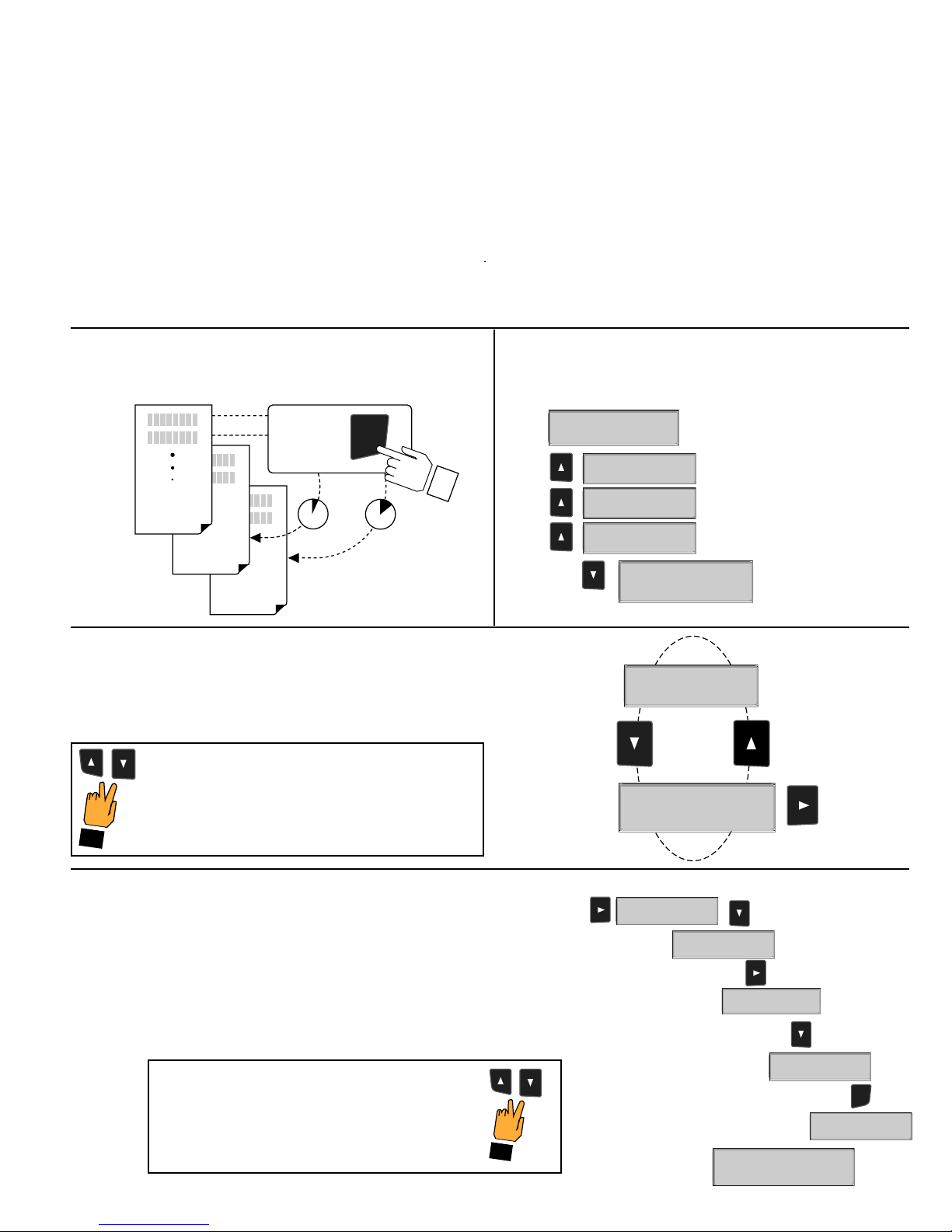
ProcessPro Editing Procedure:
Step 1. Press and hold ENTER key:
• 2 seconds to select the CALIBRATE menu
• 5 seconds to select the OPTIONS menu.
Step 2. The Key Code is UP-UP-UP-DOWN keys in sequence.
• After entering the Key Code, the display will show the first item in the selected menu.
Step 3. Scroll menu with UP or DOWN arrow keys.
Step 4. Press RIGHT ARROW key to select menu item to be edited.
• The first display element will begin flashing.
Step 5. Press UP or DOWN keys to edit the flashing element.
• RIGHT ARROW key advances the flashing element.
Step 6. Press ENTER key to sa e the new setting and return to Step 3.
OPTIONS
CALIBRATE
VIEW
2s 5s
Press &
hold for
access:
ENTER
Step 5
Step 6
Notes on Step 1:
• The View Menu is normally displayed.
• The CALIBRATE and OPTIONS menus require a KEY CODE.
Step 4
First item in
CALIBRATE menu
Step 3
Step 3: Finished Editing?
Press the UP and DOWN keys simultaneously after
saving the last setting to return to normal operation.
Press the UP and DOWN keys simultaneously
while any element is flashing. This will recall the
last saved value of the item being edited and
return you to Step 3.
Step 5: Made an Error?
Output Setpnt:
2
0.00 GPM
Output Setpnt:
1
0.00 GPM
ENTER
Output Setpnt:
10.00
GPM
Output Setpnt:
1
9
.00 GPM
Output Setpnt:
Saving
Output Setpnt:
19.00 GPM >
20.0 GPM >
Output Setpnt:
GPM >
Flow Units:
CALIBRATE: ----
Enter Key Code
CALIBRATE: *---
Enter Key Code
CALIBRATE: **--
Enter Key Code
CALIBRATE: ***-
Enter Key Code
GPM >
Flow Units:
Table of contents
Other Signet Transmitter manuals


Popular Transmitter manuals by other brands


Geo
Geo Web Pack quick start guide

Inovonics
Inovonics EchoStream EN1210W installation instructions

IKONNIK
IKONNIK KA-6 quick start guide

Rohde & Schwarz
Rohde & Schwarz SR8000 Series System manual

Audio Technica
Audio Technica UniPak ATW-T93 Installation and operation

NIVELCO
NIVELCO EasyTREK SCA-300 Series Programming manual


