Sigtronics Corporation
178 East Arrow Highway
San Dimas, CA 91773
909) 305-9399
www.sigtronics.com
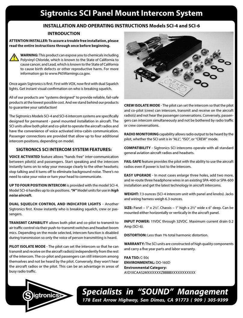
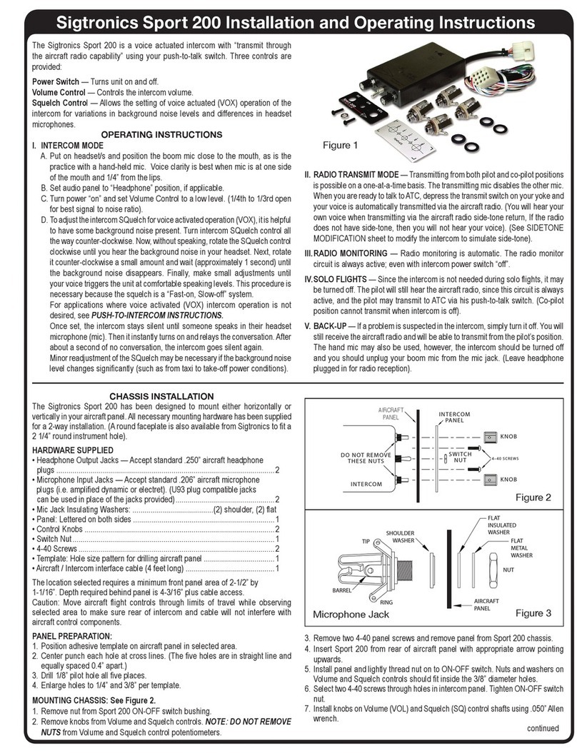
SHOULDER
WASHER
FLAT
INSULATED
WASHER
FLAT
METAL
WASHER
NUT
AIRCRAFT
PANEL
RING
BARREL
TIP
Figure 3
Microphone Jack
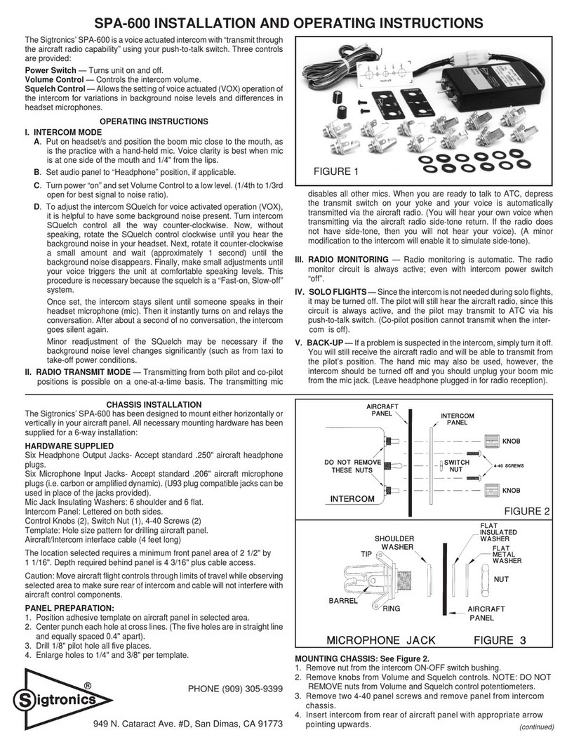
4. Insert the intercom from rear of aircraft panel with appropriate UP
arrow for horizontal or vertical installation.
5. Install panel and lightly thread nut on to ON-OFF switch. Nuts and
washers on Volume and Squelch controls should t inside the ⁄”
diameter holes.
6. Install the two 4-40 screws through the intercom and aircraft panel
holes into the intercom. Tighten ON-OFF switch nut.
7. Install knobs on Volume (VOL) and Squelch (SQ) control shafts using
.050” Allen wrench.
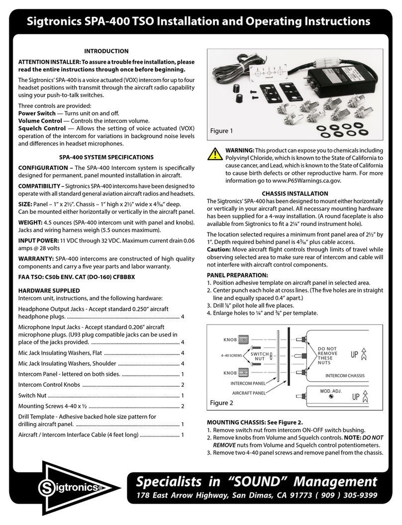
MOUNTING HEADPHONE AND MICROPHONE JACKS:
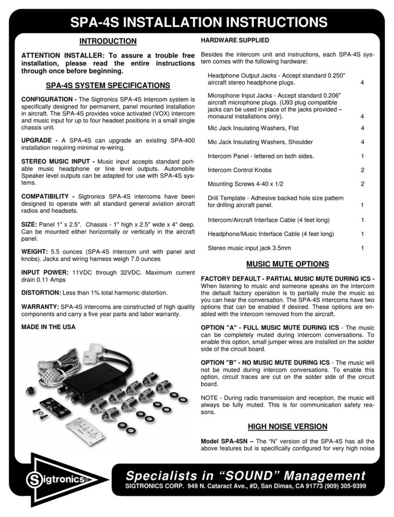
1. Select mounting areas. (One mic and one headphone jack for each
headset). Again, make sure the jacks will not interfere with aircraft
control components.
2. Drill
⁄” diameter holes for headphone jacks and install.
3. Drill ½” diameter holes for mic jacks and install with insulating
washers supplied. (See Figure 3).
WIRING INSTRUCTIONS
Connections should be made as shown in Figure 4 and indicated in Table 1
*A. White / red (pilot push-to-talk) must correspond with white / black
(pilot mic input) as shown.
*B. The blue wire from Pin 3 must be connected to the aircraft radio
headphone output- NOT the speaker output.
*C. Connect all intercom mic jack grounds to Point A as shown in Figure
4. (Use black washers supplied to insulate intercom mic jacks from
aircraft chassis ground).
*D. Do NOT connect transmit switches to white (key) wire.
*E. Red wire may be connected to either 12 (14V) or 24 (28V) power
source. No switching or adjustments are required to operate from
either source.
*F. Violet wire from Pin 12 is used for optional Push-To-Intercom switches.
FINAL CHECKOUT AND ADJUSTMENT
After the unit is installed, again check that the intercom chassis, jacks,
and wiring harness are clear of all aircraft operating controls and cause
no interference with them. Check out the intercom functions by following
the Operating Instructions.
It may be necessary at this time to adjust the intercom mic output to
the aircraft radios. A small, square, adjustable trimmer potentiometer is
provided inside the unit for this purpose. It is accessible through a hole
in the side of the case, marked “Mod. Adj.”, and can be adjusted with
a screwdriver (See Figure 2). In the event of over modulation (garbled)
or reports of weak transmissions over the aircraft radio, an appropriate
adjustment can be made. Clockwise rotation increases the output level
to the aircraft radio mic input. Counter-clockwise rotation decreases
modulation level. This adjustment sometimes needs to be made after
initial installation of the intercom or if a new radio is installed. (The
output is set for unity gain at Sigtronics.)
OPERATING INSTRUCTIONS
I. INTERCOM MODE
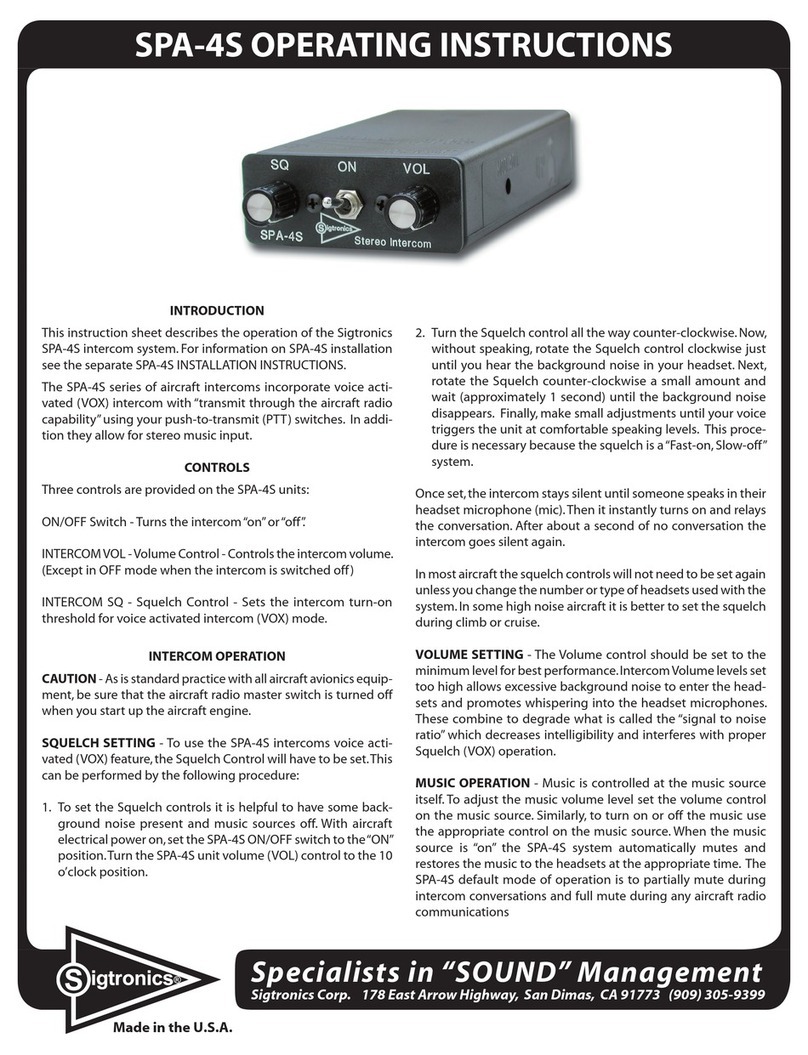
A. Put on headset/s and position the boom mic close to the mouth,
as is the practice with a hand-held mic. Voice clarity is best when
mic is at one side of the mouth and ¼” from the lips.
B. Set audio panel to “Headphone” position, if applicable.
C. Turn power “on” and set Volume Control to a low level. (1/4th to
1/3rd open for best signal to noise ratio).
D. To adjust the intercom SQuelch for voice activated operation
(VOX), it is helpful to have some background noise present. Turn
intercom SQuelch control all the way counter-clockwise. Now,
without speaking, rotate the SQuelch control clockwise until you
hear the background noise in your headset. Next, rotate it counter-
clockwise a small amount and wait (approximately 1 second) until
the background noise disappears. Finally, make small adjustments
until your voice triggers the unit at comfortable speaking levels.
This procedure is necessary because the squelch is a “Fast-on,
Slow-o” system.
Once set, the intercom stays silent until someone speaks in their
headset microphone (mic). Then it instantly turns on and relays
the conversation. After about a second of no conversation, the
intercom goes silent again.
Minor readjustment of the SQuelch may be necessary if the
background noise level changes signicantly (such as from taxi
to take-o power conditions).
E. To use the push-to-intercom feature, turn the SQuelch control on
the intercom fully counter-clockwise. Then to activate, push the
ICS push-to-intercom switch.
II.RADIO TRANSMIT MODE — Transmitting from both pilot and co-
pilot positions is possible on a one-at-a-time basis. The transmitting
mic disables all other mics. When you are ready to talk to ATC, depress
the transmit switch on your yoke and your voice is automatically
transmitted via the aircraft radio. (You will hear your own voice
when transmitting via the aircraft radio side-tone return, If the radio
does not have side-tone, then you will not hear your voice). (A minor
modication to the intercom will enable it to simulate side-tone).
III. RADIO MONITORING — Radio monitoring is automatic. The radio
monitor circuit is always active; even with intercom power switch
“o”.
IV. SOLO FLIGHTS — Since the intercom is not needed during solo
ights, it may be turned o. The pilot will still hear the aircraft radio,
since this circuit is always active, and the pilot may transmit to ATC
via his push-to-talk switch. (Co-pilot position cannot transmit when
intercom is o).
V. BACK-UP — If a problem is suspected in the intercom, simply turn it
o. You will still receive the aircraft radio and will be able to transmit
from the pilot’s position. The hand mic may also be used, however,
the intercom should be turned o and the pilot’s mic plug unpluged
from the mic jack. (Leave the headset headphone plug plugged in
for radio reception).


