SIIG AV-GM04H3-S1 User manual

HDMI over IP (fiber) Uncompressed Multicast System
P/N: AV-GM04H3-S1

Safety and Notice
The AV-GM04H3-S1 HDMI over IP (fiber) Uncompressed Multicast System has been tested
for conformance to safety regulations and requirements, and has been certified for
international use. However, like all electronic equipments, the AV-GM04H3-S1 should
be used with care. Please read and follow the safety instructions to protect yourself
from possible injury and to minimize the risk of damage to the unit.
●Follow all instructions and warnings marked on this unit.
●Do not attempt to service this unit yourself, except where explained in this manual.
●Provide proper ventilation and air circulation and do not use near water.
●Keep objects that might damage the device and assure that the placement of this
unit is on a stable surface.
●Use only the power adapter and power cords and connection cables designed for
this unit.
●Do not use liquid or aerosol cleaners to clean this unit. Always unplug the power to
the device before cleaning.
TABLE OF CONTENTS
INTRODUCTION................................................................................................................1
FEATURES.........................................................................................................................1
PACKAGE CONTENTS......................................................................................................1
SPECIFICATIONS..............................................................................................................2
PANEL DESCRIPTIONS.....................................................................................................3
IR PASS-THROUGH...........................................................................................................5
HDMI PIN DEFINITION.......................................................................................................7
CONNECTION DIAGRAM...................................................................................................8
OPERATION APPROACH..................................................................................................9
WARRANTY .....................................................................................................................14
The SELLER warrants the EX-57A-O HDMI over IP (fiber) Uncompressed
Multicast System free from defects in the material and workmanship for 1 year
from the date of purchase from the SELLER or an authorized dealer. Should this

1
INTRODUCTION
The AV-GM04H3-S1 HDMI over IP(fiber) Uncompressed*Multicast System boosts up your
video/audio transmission distance up to 300m(1000ft) over a duplex, LC terminated multimode fiber
cable in Ultra-HD 4K2K@30 format. Users can readily extend Ultra-HD sources from DVD players,
Blu-ray Disc player, PS3, PC, and any other HDMI sources broadcasting to distant display monitors
including HDMI or DVI enabled TV sets or LCD PC monitors. Besides AV-GM04H3-S1 is HDCP compliant,
and supports IR and RS-232 pass-through path.
With broadcasting management software and 10 Gigabit Ethernet network switch (supported IGMP
Snooping), AV-GM04H3-S1 is a complete Ultra-HD 4K2K@30 video broadcasting solution for digital
signage. It can transmit Ultra-HD 4K2K@30 HDMI video broadcasting over IP network. The broadcasting
format can be Point to Point, Point to Many, and Multi-Casting. Multi-casting is based on Managed
Gigabit Switch with 802.1Q VLAN function which provides control remotely, so multi video and source
allowed and supported.
FEATURES
●Supports uncompressed HDMI Deep Color, full 3D & 4K2K@30
●HDCP & EDID Bypass
●CEC support
●Auto equalization
●Pure unaltered uncompressed 7.1ch digital HDMI over fiber transmission
●DTS-HD Master Audio and Dolby TrueHD high bit rate audio support
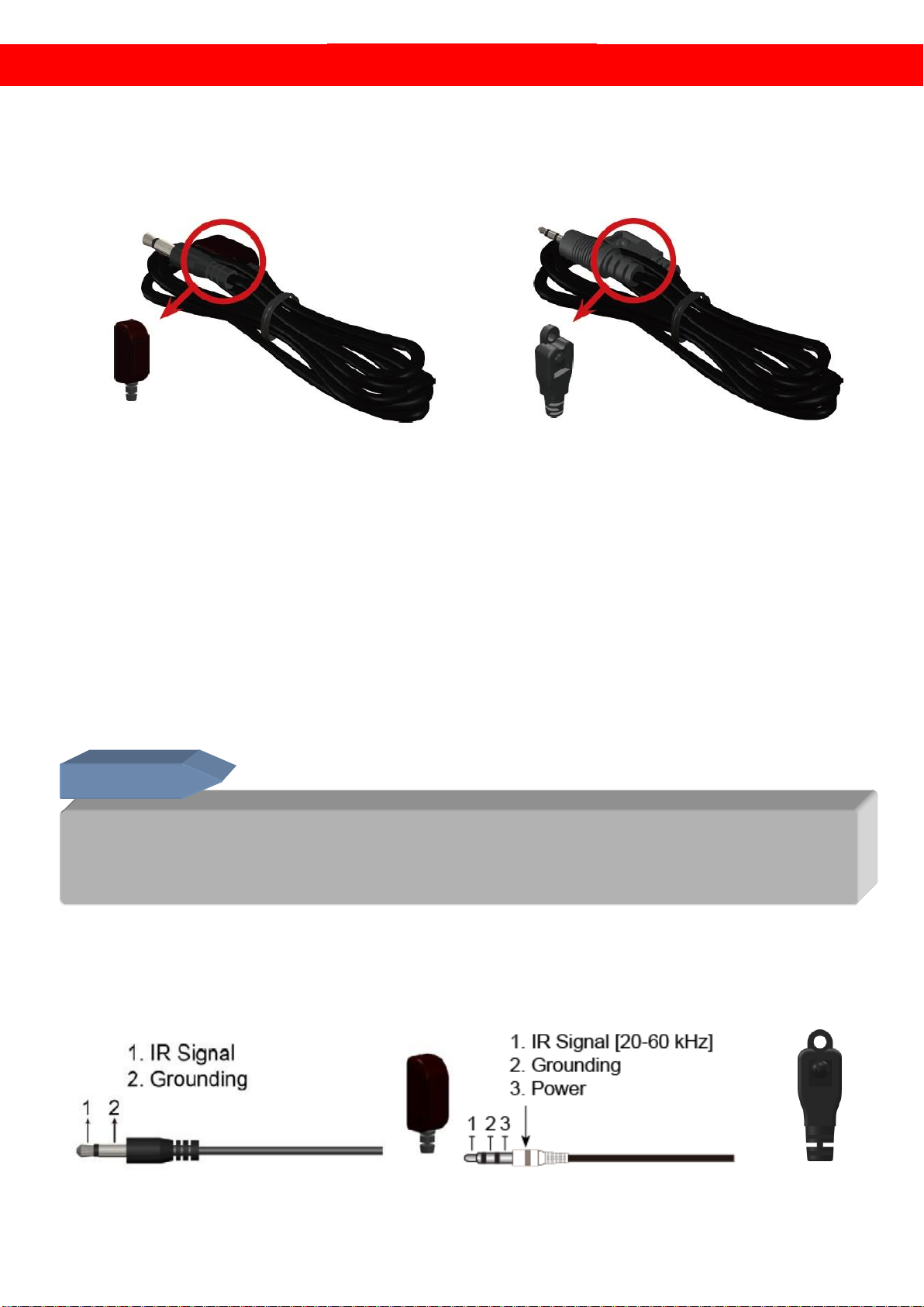
●Supports full frequency IR signal from 20KHz to 60KHz
●Bi-directional IR path-through
●Full Duplex RS-232 control up to 115,200 bps through connector
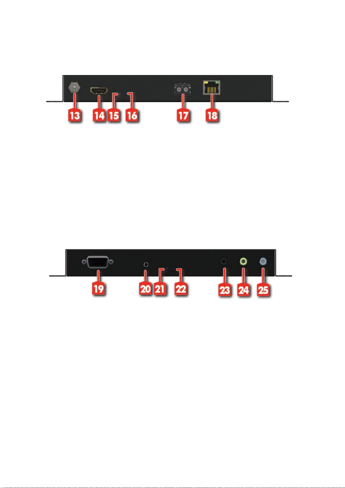
●Integrated port for LAN/ network device
●Fiber extension and connection to a 10GbE Ethernet Switch (supported IGMP Snooping)
●Support software to configure & update device and to control the switching operation of the
various signal types
●Support IP pass-through
●Support seamless switching
PACKAGE CONTENTS
●1x AV-GM04H3-S1 [TX & RX]
●1x IR blaster
●1x IR receiver
●2x DC 5V
●1x User Manual
* Up to 4K@60 HDR
4K@60 4:4:4 needs Light compress

2
SPECIFICATIONS
Model Name
AV-GM04H3-S1
Technical
AV-GM04H3-S1[Tx]
AV-GM04H3-S1[Rx]
Role of usage
Transmitter [TX]
Receiver [RX]
HDMI compliance
HDMI Deep Color, full 3D & 4K2K@30
HDCP compliance
Yes
Video bandwidth
Single-link 340MHz [10.2Gbps]
Video support
480i / 480p / 720p / 1080i / 1080p60 / 4K2K@30 / 4K2K@60 HDR
HDMI over fiber
Yes
Audio support
Surround sound [up to 7.1ch] or stereo audio
Equalization
Auto
Input TMDS signal
1.2 Volts [peak-to-peak]
Input DDC signal
5 Volts [peak-to-peak, TTL]
ESD protection
Human body model —±15kV [air-gap discharge] & ±8kV [contact
discharge]
PCB stack-up
6-layer board [impedance control —differential 100Ω; single 50Ω]
IR pass-thru
Bi-directional
RS-232 support
Yes
Input
1x HDMI
2x 3.5mm
1x fiber
1x 3.5mm
Output
1x fiber
1x 3.5mm
1x HDMI
2x 3.5mm
In / Out
1x RS-232
1x RJ-45(Ethernet)
1x RS-232
1x RJ-45(Ethernet)
HDMI source control
Controllable via IR pass-through from RX to TX with IR extenders
HDMI connector
Type A [19-pin female]
RJ-45 connector
WE/SS 8P8C(Reverse Mode)
Rotary control switch
None
3.5mm connector
IR receiver / IR blaster
Mechanical
AV-GM04H3-S1[Tx]
AV-GM04H3-S1[Rx]
Housing
Metal enclosure
Dimension
s
[L x W x H]
Model
195 x 122 x 25mm[7.7" x 4.8" x 1”]
Package
325 x 196 x 92mm[12.7” x 7.7” x 3.6”]
Carton
490 x 426 x 352mm[1’6” x 1’4” x 1’2”]
Weight
Model
656g [23.1oz]
656g [23.1oz]
Package
2393g [5.3lbs]
Fixedness
Wall-mounting case with screws
Power supply
5V4A
Power consumption
Max 12W
Operation
temperature
0~40°C [32~104°F]
Storage temperature
-20~60°C [-4~140°F]
Relative humidity
20~90% RH [no condensation]

3
PANEL DESCRIPTIONS
Transmitting unit ►AV-GM04H3-S1-TX
Front Panel
1. +5V DC: Connect to a 5V power supply unit
2. HDMI IN: Connect to a HDMI source with a HDMI male-male cable
3. Status LED: When device read the firmware, the indicator LED will light
4. Signal LED: When user connect to the source, the indicator LED will light
5. SFP OUT: Connect a duplex, LC terminated multimode fiber cable
6. Ethernet Port: Ethernet control port
Rear Panel
7. RS-232: Connect to serial port device with a DSUB-9 male-male or male-female cable here
8. Transmission Status LED: When device transmit the Ethernet frames at a rate of 10Gb/s, the
indicator LED will light
9. Receiving Status LED: When device receive the Ethernet frames at a rate of 10Gb/s, the indicator
LED will light
10. Audio IN: Connect an audio source device here
11. IR Receiver: Infrared 3.5mm socket for plugging in the extension cable of IR receiver
12. IR Blaster: Infrared 3.5mm socket for plugging in the extension cable of IR blaster

4
Receiving unit ►AV-GM04H3-S1-RX
Front Panel
13. +5V DC: Connect to a 5V power supply unit
14. HDMI OUT: Connect to a HDMI display with a HDMI male-male cable
15. Status LED: When device read the firmware, the indicator LED will light
16. Signal LED: When user connect to the display, the indicator LED will light
17. SFP IN: Connect a duplex, LC terminated multimode fiber cable
18. Ethernet Port: Ethernet control port
Rear Panel
19. RS-232: Connect to serial port device with a DSUB-9 male-male or male-female cable here
20. EDID Button: To learn EDID from display
21. Transmit Status LED: When device transmit the Ethernet frames at a rate of 10Gb/s, the
indicator LED will light
22. Receive Status LED: When device receive the Ethernet frames at a rate of 10Gb/s, the indicator
LED will light
23. Audio OUT: Connect an audio output device (e.g. speaker or headphone) here
24. IR Receiver: Infrared 3.5mm socket for plugging in the extension cable of IR receiver
25. IR Blaster: Infrared 3.5mm socket for plugging in the extension cable of IR blaster

5
IR PASS-THROUGH
IR Extenders
IR Blaster
IR Receiver
IR Sockets
IR BLASTER: plug in the IR blaster to emit all IR command signals received from the IR
receiver from the other enf to control the devices corresponding to the IR signals.
IR RECEIVER: plug in the IR receiver to receive all IR command signals from the IR remote
controls of the corresponding devices.
Definition of IR Earphone Jack
IR Blaster
IR Receiver
Incorrect placement of IR Blaster and Receiver may result in the failure of the IR
extenders. Please check carefully before plugging in the IR extender to the
respective IR sockets. Warranty will not cover the damage.
CAUTION!

6
You can buy any IR extension cables in the market that are compatible to the definition of
the IR sockets for the matrix if necessary for replacement use. However, IR cables longer
than 2m (6-ft) may not work.

7
HDMI PIN DEFINITION
Type A (Receptacle) HDMI
Pin 1
TMDS Data2+
Pin 11
TMDS Clock Shield
Pin 2
TMDS Data2 Shield
Pin 12
TMDS Clock–
Pin 3
TMDS Data2–
Pin 13
NC
Pin 4
TMDS Data1+
Pin 14
Reserved (N.C. on device)
Pin 5
TMDS Data1 Shield
Pin 15
SCL
Pin 6
TMDS Data1–
Pin 16
SDA
Pin 7
TMDS Data0+
Pin 17
DDC/CEC Ground
Pin 8
TMDS Data0 Shield
Pin 18
+5V Power
Pin 9
TMDS Data0–
Pin 19
Hot Plug Detect
Pin 10
TMDS Clock+

8
CONNECTION DIAGRAM

9
OPERATION APPROACH
Software Control through Ethernet port
1. System Requirement
(1) OS information : MS Win XP/7/8/10
(2) Baud Rate: 57600
(3) Software size: 17MB
(4) Minimum RAM requirement: 256MB
2. Control Interface
Before you execute the software, please open the software control program
(based on your operating system).
After executing the control software, the following interface will pop up.
1
Connect Control Software
5
Analog Audio Routing
2
Video Switching (Mapping)
6
RS-232 Routing
3
Wall Switching
7
Infrared Routing
4
HDMI Audio Routing
(1) Video Switching (Mapping)
Dragging the Encoders icon to Decoders icon to do input/output mapping. After setting
the mapping, you also can click the right button to set up more video mode (ex. stop
video).

10
(2) Wall Switching
User can define wall size by entering the wall parameters. Dragging Encoders or
Decoders to Wall and Wall Decoders icon to setup the video wall function. Please note
that the resolution of each Wall Decoders is divided by the wall size. For example, the
resolution of wall is 1920x1080 and the wall size is 4 (2x2), the resolution of each wall
decoders is 960x540. If you want to mute the video or remove the video wall, please
click the right button to select those function.
(3) HDMI/Analog Audio Routing
This function provides you to control where the audio transmit.

11

12
(4) RS-232 Routing
Bi-directional RS-232 signal are transmitted between the device transmitter and receiver.
Dragging the RS-232 icon of Senders to Receivers to make connection and
sending/receiving data.
(5) Infrared Routing
Bi-directional IR signal can be transmitted between the transmitter and receiver. The IR
signal can be generated either from receiver or a control system. You can drag the
Infrared Senders icon to Receivers to do the Infrared Routing.

13
(6) Custom Setting
In the right part of the control interface, we provide the save function for user to save
the video switching (mapping) into the flash memory. User also can rename the custom
setting.

14
WARRANTY
The SELLER warrants the AV-GM04H3-S1 HDMI over IP (fiber) Uncompressed Multicast
System free from defects in the material and workmanship for 3 years from the date of
purchase from the SELLER or an authorized dealer. Should this product fail to be in good
working order within 3 years warranty period, The SELLER, at its option, repair or replace
the unit, provided that the unit has not been subjected to accident, disaster, abuse or any
unauthorized modifications including static discharge and power surge. This warranty is
offered by the SELLER for its BUYER with direct transaction only. This warranty is void if the
warranty seal on the metal housing is broken.
Unit that fails under conditions other than those covered will be repaired at the
current price of parts and labor in effect at the time of repair. Such repairs are warranted
for 90 days from the day of reshipment to the BUYER. If the unit is delivered by mail,
customers agree to insure the unit or assume the risk of loss or damage in transit. Under
no circumstances will a unit be accepted without a return authorization number.
The warranty is in lieu of all other warranties expressed or implied, including without
limitations, any other implied warranty or fitness or merchantability for any particular
purpose, all of which are expressly disclaimed.
Proof of sale may be required in order to claim warranty. Customers outside Taiwan
are responsible for shipping charges to and from the SELLER. Cables and power adapters
are limited to a 30 day warranty and must be free from any markings, scratches, and neatly
coiled.
The content of this manual has been carefully checked and is believed to be accurate.
However, The SELLER assumes no responsibility for any inaccuracies that may be
contained in this manual. The SELLER will NOT be liable for direct, indirect, incidental,
special, or consequential damages resulting from any defect or omission in this manual,
even if advised of the possibility of such damages. Also, the technical information
contained herein regarding the AV-GM04H3-S1 features and specifications is subject to
change without further notice.
April, 2018
Support
For more info or tech support
http://www.siig.com/support
Table of contents
Other SIIG Microphone System manuals