Silca FLASH MOBILE User manual

Operating Manual
Translation of original instructions
D4A4048XA
vers. 2.0
EN
FLASH
MOBILE

© 2021 SILCA S.p.A - Vittorio Veneto
This manual has been drawn up by SILCA S.p.A.
All rights reserved. No part of this publication may be reproduced or used in any form or by any means (photocopying,
microfilm or other) without the written permission of SILCA S.p.A.
Edition: March 2021
Printed in India
by MINDA SILCA Engineering Ltd.
Plot no.37, Toy City, GREATER NOIDA (U.P.) - 201308
The Manufacturer declines any responsibility for possible inaccuracies in this document due to printing or transcription errors.
The Manufacturer reserves the right to alter the information without prior notice, except when they aect safety. This document or any of its parts
cannot be copied, altered or reproduced without written authorization from the Manufacturer. Keep the manual and look after it for the entire life cycle
of the machine.
The information has been drawn up by the manufacturer in his own language (Italian) to provide users with the necessary indications to use the key-
cutting machine independently, economically and safely.
IMPORTANT NOTE: in compliance with current regulations relating to industrial property, we hereby state that the trade-marks or trade names men-
tioned in our documentation are the exclusive property of authorized manufacturers of locks and users.
Said trade-marks or trade names are nominated only for the purposes of information so that any lock for which our keys are made can be rapidly
identied.

IMPORTANT
ATTENTION:
1) Following the norms of air transport safety, the battery provided in the machine is in discharged
condition. The battery connection of the machine is also disengaged from PCB. This point is also
applicable to Shipping by Sea.
2) Please engage the battery connection and make sure to charge the machine up to 100% before
use.
INSTRUCTIONS:
A) Carefully turn the key-cutting machine onto its back as shown in below picture.
B) To open the Electric Cover, Open screws (R1), (R2) & (R3) as shown below.
R2
R3
R1
T
N
C) Make sure that both switches (T) and (N) are turned o.
D) Connect the Battery Wire to the PCB in the Battery Terminal as shown below
E) Tight the Electric Cover and return the machine to its upright position on the work top. Before use, please charge
the machine with its adapter till the LED shows 100% Charged.
Operating manual FLASH MOBILE

INDEX
USE OF THE MANUAL....................................................................................................................... 1
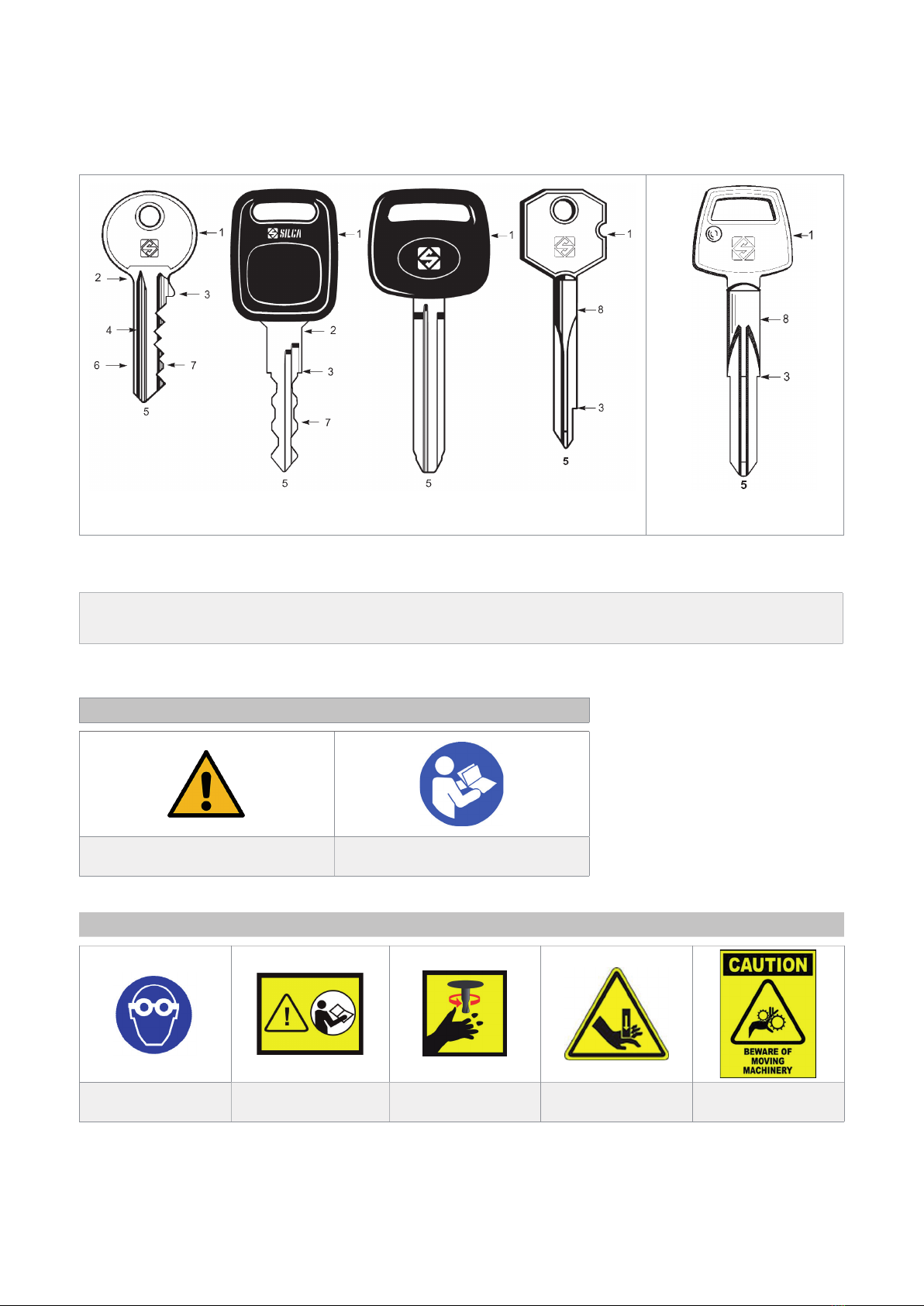
GENERAL WARNINGS....................................................................................................................... 3
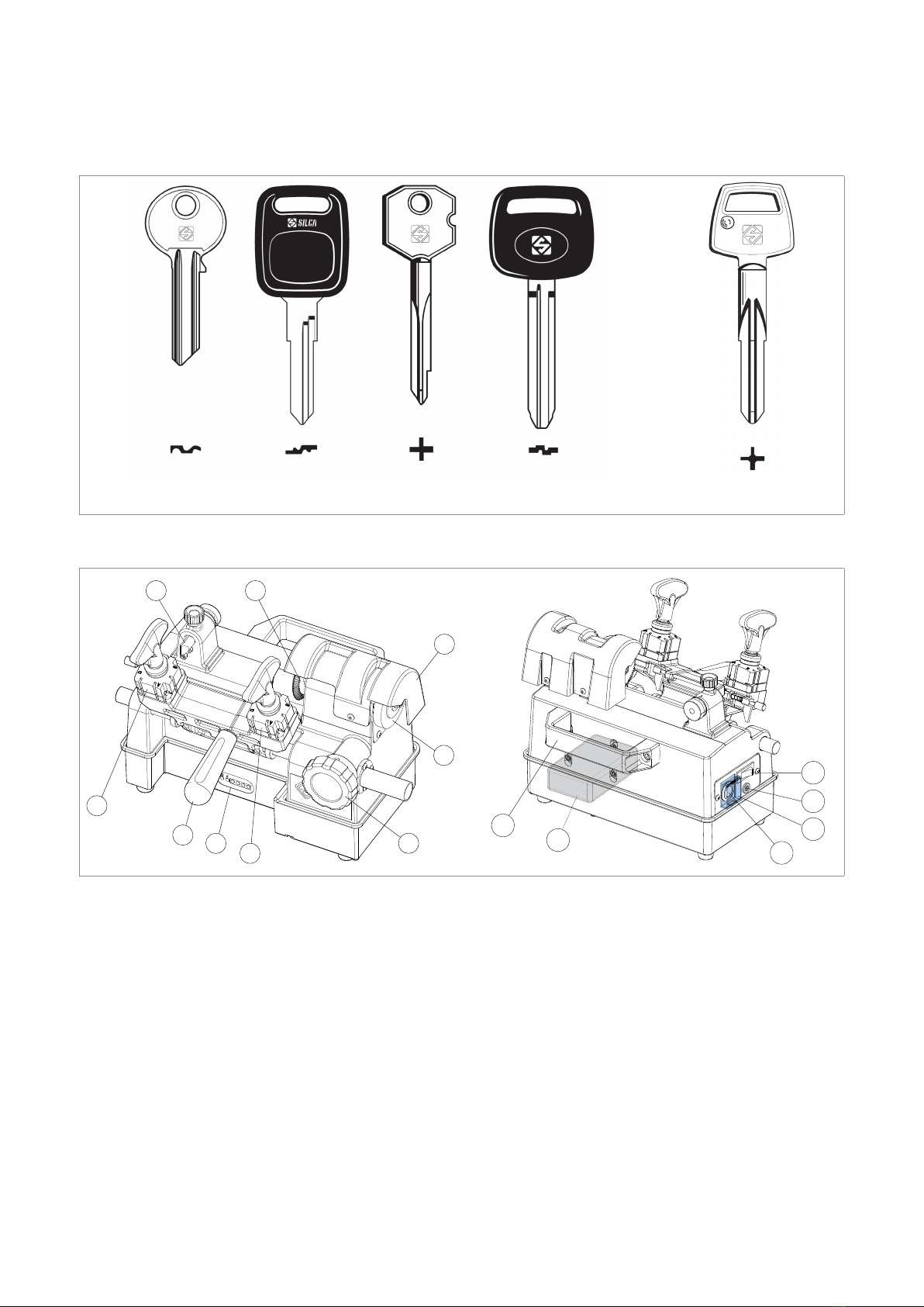
1 MACHINE DESCRIPTION....................................................................................................................4
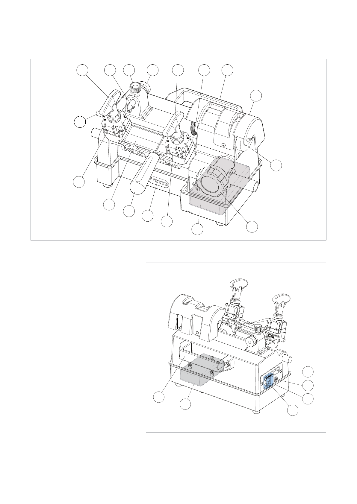
1.1 Main working parts......................................................................................................................6
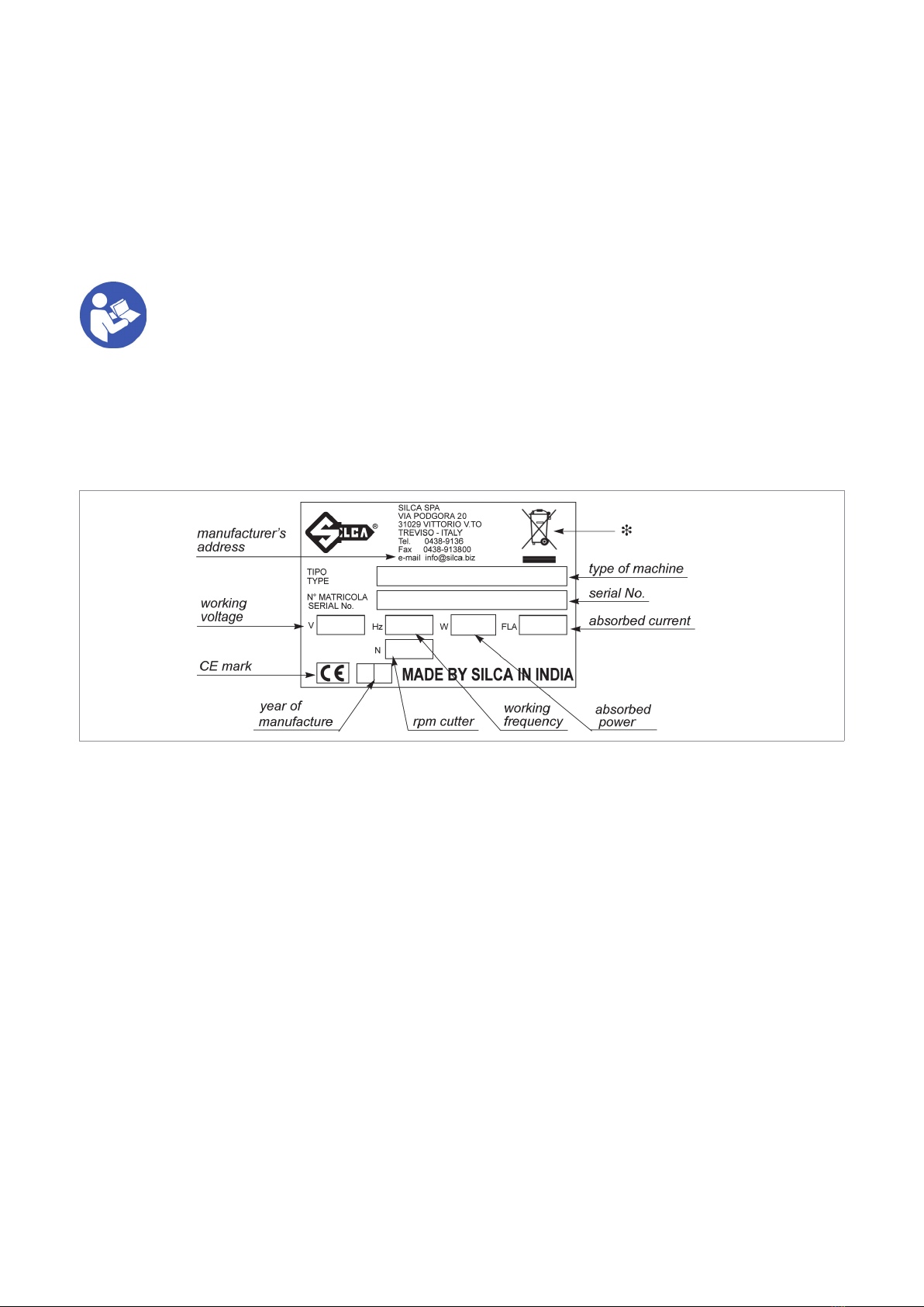
1.2 Technical Data ............................................................................................................................7
1.3 Battery ........................................................................................................................................8
1.4 Electric circuit..............................................................................................................................9
1.5 Accessories provided................................................................................................................10
2 TRANSPORT......................................................................................................................................11
2.1 Packing .....................................................................................................................................11
2.2 Unpacking .................................................................................................................................11
2.3 Handling the machine ...............................................................................................................11
3 MACHINE INSTALLATION AND PREPARATION ..............................................................................12
3.1 Checking for damage................................................................................................................12
3.2 Environmental conditions..........................................................................................................12
3.3 Positioning ...............................................................................................................................12
3.4 Separate parts .........................................................................................................................12
3.4.1 Carriage handle ..............................................................................................................12
3.4.2 Fixing bracket..................................................................................................................13
3.5 Connection to external sources ................................................................................................14
4 MACHINE REGULATION AND UTILIZATION ....................................................................................15
4.1 Checking and calibration...........................................................................................................15
4.2 Calibration.................................................................................................................................15
5 CUTTING OPERATIONS .................................................................................................................18
5.1 Key cutting ................................................................................................................................18
5.1.1 Clamp rotation ................................................................................................................19
5.1.2 Securing the keys in the clamps .....................................................................................19
5.1.3 Key cutting ......................................................................................................................20
5.2 Using the accessories...............................................................................................................20
6 MAINTENANCE..................................................................................................................................22
6.1 Replacing the brush..................................................................................................................22
6.2 Replacing the cutting tool..........................................................................................................23
6.3 Replacing the tracer point ........................................................................................................23
6.4 Depth regulation (clamp protection)..........................................................................................24
6.5 Access to the lower compartment.............................................................................................24
6.6 Battery Replacement Instructions ............................................................................................25
6.7 Replacing the main switch ........................................................................................................26
6.8 Replacing the motor start switch...............................................................................................27
6.9 Replacing and/or adjusting tension on the belt.........................................................................28
7 DISPOSAL..........................................................................................................................................29
8 ASSISTANCE .....................................................................................................................................30
8.1 How to request service .............................................................................................................30
Operating manual FLASH MOBILE

USE OF THE MANUAL
This manual has been drawn up by the Manufacturer and is an integral part of the machine literature. The manual
gives information that is obligatory for the operator to know and which makes it possible to use the machine safely.
User’s Manual
This user’s manual is provided because it is essential for proper use and maintenance of the machine. The manual
must be kept carefully throughout the life of the machine, including the decommissioning stage. Keep in a dry place
close to the machine where it is always at hand for the operator.
ATTENTION: IT IS OBLIGATORY to read the manual carefully before using the machine.
Readers’ characteristics
This manual must be read and its contents acquired by those who will use the machine.
Manufacturer’s ID
FLASH MOBILE has an ID plate located on the right side of the machine, showing the serial number.
Fig. 1
(*) see chap. 7 DISPOSAL.
How to apply for after-sales service
Silca provides purchasers of the FLASH MOBILE with After-Sales Service. For the total safety of the operator and
machine, any service not described in the manual must be carried out by the manufacturer or in the special Service
Centres recommended by Silca.
At the end of the manual there is a list of manufacturers’ and authorized Service Centre addresses; if the manual
was downloaded is necessary visit the website to see the contacts (www.silca.biz).
The warranty card attached to the machine covers free repairs or replacement of faulty parts for 24 months from
the date of purchase**.
All service must be agreed by to by the user with Silca or the Service Centre.
(**) Damage caused by negligence or wrong use of the machine by the user will null the warranty.
Battery and Charging Adapter life are 500 nos. charging cycle or 6 months which ever is earlier.
Operating manual FLASH MOBILE
Copyright Silca 2021 1

TERMINOLOGY
For those inexperienced in the subject of keys and key cutting, below is an illustration of the most frequently used
terms:
On machines
for LAR region
Fig. 2
1) Head
2) Neck
3) Stop
4) Blade
5) Tip
6) Back
7) Cuts
8) Stem
GRAPHICS IN THE USER’S MANUAL
Pay attention Obligation to read
the manual
GRAPHICS ON THE FLASH MOBILE MACHINE
Obligatory use
of safety goggles
Read instructions
before use
WARNING! cutting tool
in motion
WARNING!
Crushing hazard
WARNING!
Entanglement hazard
Operating manual FLASH MOBILE
Copyright Silca 2021
2

GENERAL WARNINGS
FLASH MOBILE is designed to the principles of European Standards (CE). Right from the design stage solutions
have been adopted to eliminate hazards for the operator in all the stages of use: handling, regulation, use and
maintenance.
The materials used in manufacture and the components employed in using FLASH MOBILE are not dangerous and
ensure that the machine complies with current standards.
Silca S.p.A. has also experimented and applied numerous technical solutions that allow the key-cutting machine to
optimize the quality of the cut keys.
To guarantee maintaining these results over time, please follow the instructions below:
• Observe the procedures described in this manual;
• Always use Original Silca Tools as they are designed to make the best of FLASH MOBILE and provide
quality key-cutting;
• Use Silca key blanks, made with top quality materials;
• Have the key-cutting machine checked periodically by an authorized Silca After-Sales Service Centre;
• Use only original battery and battery charger.
• Do not try to disassemble Battery, or give pressure on it, expose to heat or re as it may EXPLODE.
• Do not run the motor while charging.
• Always use Silca Original Spare Parts. Beware of imitations!
NORMAL USE
FLASH MOBILE key-cutting machine must be installed and used according to the rules and specifcations established
by the manufacturer.
The key-cutting machine must be used only by skilled personnel (professional use).
The FLASH MOBILE key-cutting machine is designed for use on business or industrial premises (e.g. hardware
shops, key cutting centers, etc...).
Any other use dierent from that indicated in this manual will cause the forfeiture of all customers’ rights to make
claims on Silca S.p.A. and may be an unknown source of hazard for the operator or third parties.
ATTENTION: negligent use or failure by the operator to observe the instructions in this manual are
not covered by the warranty and the manufacturer declines any responsibility in such cases.
SAFETY
The key-cutting machine is built entirely to standards. The operations for which it has been designed are easily
carried out at no risk to the operator.
The adoption of general safety precautions (wearing protective goggles) and observation of the instructions provided
by the manufacturer in this manual eliminate all human error, unless deliberate.
The key-cutting machine is designed with features which make it completely safe in all its parts.
RESIDUAL RISKS
There are no further risks arising from the use of the machine.
SAFETY REGULATIONS
• Always provide to turn o the machine when not in service and before carrying out any kind of
maintenance work.
• Always work with dry hands free of grease or oil.
• Never pull the battery charger cord too hard and ensure that it does not come into contact with oil,
sharp objects or heat source.
• Do not use the machine in dangerous environments (wet or damp).
• All visitors, especially children, must stay at a safe distance from the machine and must never come
into contact with the electric wiring. This equipment should not be used where children may be present.
• Remove the battery wire connection from PCB before leaving the machine unused for a long period
of time.
Operating manual FLASH MOBILE
Copyright Silca 2021 3

1 MACHINE DESCRIPTION
FLASH MOBILE is a professional cutting machine for duplicating at keys used with cylinder, car locks and cruciform
keys.
On machines
for "LAR"region
Fig. 3
The main parts of the machine are described below:
B
A
D
K
D
H
M
F
L
Z
T
P
K1
N1
N
Fig. 4
• Battery power supply
The machine is powered by a lithium-ion battery (K1) located inside the machine body. To recharge the battery, use
the charging device supplied with the machine.
The charge level is shown on the display (K) located on front of the machine.
With fully charged battery, you can cut:
-
about 200 steel keys; - about 300 brass keys.
• Main power switch
The machine is turned on by means of the switch (N) located on its left-hand side. It is located inside a switch
protection (N1) to prevent from becoming switched on inadvertently. Switch protection (N1) should be lifted to
switch ON the switch (N) and closed when the machine is not in use.
• Motor start switch
The switch (T) starts the motor.
Operating manual FLASH MOBILE
Copyright Silca 2021
4

• Motor and transmission unit
Motor transmission takes place by belt. On the right-hand side of the motor there is the transmission shaft which
moves the cutting tool (F) and the brush (M). These components are protected by the protective cover (L).
• Clamp carriages
Carriage (C) is moved horizontally by means of knob (B). The carriage holds 2 clamps (D) and has a handle (A) for
front movement.
• Cutting unit
The cutting unit contains the actual working parts of the FLASH MOBILE key-cutting machine, which operate
together to cut and nish keys “read” from the originals. The working parts are described below:
Cutting Tool
The cutting tool (F) is the part of the FLASH MOBILE used for cutting key blanks. The cutting tool is in HSS super
rapid steel and is protected by a special cover (L) to ensure safe operation.
Tracer point
The tracer point (H), dedicated to reading the cuts on keys to be copied is housed on the left-hand side of the
machine. Depth is easily regulated by means of the relevant centesimal ring nut (G).
Clamps
The clamps (D) are rotating and four-sided to allow perfect closure of the key placed on its back or prole in the
case of keys with symmetrical cuts (cap.5.1).
Clamp knobs
The clamps are locked by two ergonomic knobs (E), which ensure perfect grip on the keys with only slightly locking
force.
Gauges
Next to the clamps there is a rod with two gauge tabs to control key alignment for shoulder gauged keys.
Brush
The purpose of the brush (M) is to deburr the keys after cutting. It is made of accident proof material and is protected
by a shield (L).
Operating manual FLASH MOBILE
Copyright Silca 2021 5

1.1 Main working parts
B
A
D
K
D
E
Q
J
H
P
M
F
G
L
C
E
K1
Fig. 5
A - carriage handle
B - carriage movement knob
C - clamp carriage
D - clamps
E - clamp knobs
F - cutting tool
G - tracer point ring nut
H - tracer point
J - tracer point locking knob
K - charge viewer display
K1 - battery
L - cutter/brush cover
M - brush
N - main power switch
N1 - main power switch protection
P - handle for machine transport
Q - gauges knob
T - motor start switch
Z - socket for battery charger
Z
T
P
K1
N1
N
Fig. 6
Operating manual FLASH MOBILE
Copyright Silca 2021
6

1.2 Technical Data
Power supply: Li-Ion Battery 22,2V 2900 mAh
Power adaptor: MeanWell GST60A24-P1J - 24V - 2.5A
Cutter motor: 12VDC 120W - 500 hours of life cycle
Movements: by rectied carriage shaft and rack
Cutting tool: HSS Super Rapid Steel - coated
Tool speed: 2200 rpm +/-10%
Runs (maximum length of cuts): 42 mm
Dimensions: width: 320 mm - depth: 250 mm - height: 250 mm
Mass: Kg. 8.7
Noise level: sound pressure Lp(A) =
- for Brass key: 78 dB(A)
- for Steel key: 80 dB(A)
Operating manual FLASH MOBILE
Copyright Silca 2021 7

1.3 Battery
On the front side, the machine bears a LED display showing the battery charge level.
Fig. 7
On full charge, it will turn GREEN.
Remaining same.
GREEN: the battery has been fully charged.
Unplug the power cord.
With fully charged battery, the key cutting machine
can encrypt from 200 to 300 keys.
During charging, this LED will turn RED.
On reaching full charge, this LED will
turn OFF.
Charging may take 3 - 4 hours.
RED: charging.
Led Indicators The 4 led show the charge level
WARNINGS FOR CHARGING THE BATTERY
• Use original battery charger and cord.
• Use a grounded power outlet.
• It is recommended not to perform any maintenance operation during charging.
Z
Fig. 8
Operating manual FLASH MOBILE
Copyright Silca 2021
8

1.4 Electric circuit
The main parts of the electric circuit on the key-cutting machine are listed below:
1) Power adaptor
2) Socket for battery charger
3) Main switch
4) Card
5) 22.2V battery
6) 12V-DC motor
7) Motor switch 24V DC 16A
1
2
3
4
5
6
7
Black
Red
Red
Black
Black
Black M
Jack Socket
Push Button
on/ off Switch
PCB Board
Motor
+ -
+ -
Battery
1
2
3
4
5
6
AC/DC SWITCHING ADAPTOR
MODEL: GST60A24-P1J
INPUT: 100-240 VAC,50/60Hz,1.4A
OUTPUT: 24V 2.5A, 60W MAX
Switch
6
7
4
1
3
5
2
Fig. 9
Operating manual FLASH MOBILE
Copyright Silca 2021 9

1.5 Accessories provided
FLASH MOBILE comes with a set of accessories for its operation and maintenance (tools, hex wrenches, fuses)
supplied in a special tool kit comprising:
allen key 2,5 mm adjusting keys (2 pcs)
allen key 3 mm steel bars (2 pcs)
allen key 4 mm steel pin Ø 1,20 mm
cutter release rod steel pin Ø 1,70 mm
universal adapter (for "LAR" region) stubby screwdriver
Separately
:
xing bracket battery charger device
Operating manual FLASH MOBILE
Copyright Silca 2021
10

2 TRANSPORT
FLASH MOBILE key-cutting machine is easily transported and is not dangerous to handle.
The packed machine can be carried by one person.
2.1 Packing
The FLASH MOBILE is packed in a strong cardboard box, the dimensions of which are shown in Fig. 10 suciently
robust to be used for storing the machine for long periods.
Inside the box the machine is enclosed in expanded polymer shells. The shells and cardboard box ensure safe
transportation and protect the machine and all its parts.
Fig. 10
Keep dry Handle with care This side up
NOTE:
to avoid damaging the key-cutting machine it must always be transported in its packing case. This will
prevent sudden movements or rough handling from damaging the machine, persons or things.
2.2 Unpacking
To remove the machine from the packing box:
1) Cut the straps with scissors and remove,
2) Open the box without damaging it as it may be used again (e.g. removals, dispatch to the manufacturers for
repairs or servicing),
3) Check the contents of the box, which should comprise:
-
1 FLASH MOBILE key-cutting machine packed in a protective shell;
-
1 set of documents, including: operating manual, spare parts list and warranty;
-
1 carriage handle;
-
1 battery charging device;
-
1 tool set;
-
1 xing bracket;
4) Remove the key-cutting machine from the protective shell.
2.3 Handling the machine
When the FLASH MOBILE has been unpacked, place it directly on its workbench.
This operation can be carried out by one person.
ATTENTION: rmly hold the handle (P) for machine transport, and no other part, to lift and carry the
machine
.
Operating manual FLASH MOBILE
Copyright Silca 2021 11

3 MACHINE INSTALLATION AND PREPARATION
The key-cutting machine can be installed by the purchaser and does not require any special skills. However, some
checks and preparation for use need to be carried out by the operator.
3.1 Checking for damage
FLASH MOBILE key-cutting machine is solid and compact and will not normally damage if transport, unpacking and
installation have all been carried out according to the instructions in this manual.
However, it is always advisable to check that the machine has not suered any damage.
3.2 Environmental conditions
To ensure that the best use is made of the key-cutting machine, certain parameters must be borne in mind: damp,
badly ventilated sites should be avoided.
The ideal conditions for the machine are:
-
temperature: between 10°C and 40°C; relative humidity: 60% ; room illumination: approximately 500 Lux.
3.3 Positioning
1) Place the key-cutting machine on a horizontal surface, solid enough to take the weight (8,7 Kg).
-
to work with ease, we suggest that the workbench be
approximately the height of the operator’s hip.
-
it is important to leave clearance of at least 30cm (12”)
behind the machine and on each side to ensure proper
ventilation (Fig. 11).
2) Make sure machine voltage is suitable for the mains
supply and that the latter is earthed with a dierential
switch.
3) Read instruction “IMPORTANT” initial page of the manual
carefully and connect the power lead (power pack) to the
machine (chap.3.5).
Fig. 11
3.4 Separate parts
The separately packed parts must be installed on the FLASH MOBILE key-cutting machine by the purchaser, as
follows:
3.4.1 Carriage handle
Screw the handle (A) onto the carriage (A) (Fig. 12).
Fig. 12
100/120 cm
30 cm
30 cm
30 cm
A
Operating manual FLASH MOBILE
Copyright Silca 2021
12

3.4.2 Fixing bracket
The machine can be xed to the workbench with a special bracket (provided).
Proceed as follows:
ATTENTION: turn o the machine with motor switch (T), turn o main power switch (N), close the
switch protection cover (N1) and check that it is NOT connected to the battery.
1) Paying attention turn the machine slowly onto its back.
2) To remove the Bottom Plate, loosen and remove the front screws (R1), (R2) and (R3) (Fig. 13).
3) Loosen screw (R4) from the bottom plate (Fig. 13).
4) Remove the washers (R5) (Fig. 14) from the front foot and x the Fixing Bracket it its place (Fig. 15).
5) Return the machine to its upright position and x it on the work top (Fig. 16).
Fig. 13 Fig. 14
Fig. 15 Fig. 16
Operating manual FLASH MOBILE
Copyright Silca 2021 13

3.5 Connection to external sources
Before, please ensure Battery terminal should be connected. Do not use the machine during charging as it
may cause over heating of battery and may damage critical component.
To charge the battery, it is necessary to connect the charger to the socket (Z) of the machine and to the power
source.
Fig. 17
Operating manual FLASH MOBILE
Copyright Silca 2021
14

4 MACHINE REGULATION AND UTILIZATION
4.1 Checking and calibration
The cutting tool on the machine is the part used to cut the key blanks and should be periodically checked and
replaced, if necessary.
Every time the cutting tool is changed, and during periodical operational tests, check calibration.
4.2 Calibration
The FLASH MOBILE key-cutting machine requires two types of calibration: axis and depth.
Axis calibration:
Axis calibration is regulation of the space between cutting and the stop (Fig. 18 and Fig. 19).
The axis setting for the FLASH MOBILE is xed and is established on assembly in our workshops.
Fig. 18
Fig. 19
Operating manual FLASH MOBILE
Copyright Silca 2021 15

Depth calibration:
Depth calibration is regulation of the cutting depth (Fig. 18). Proceed as follows:
1) Turn o the machine with motor switch (T), turn o main power switch (N), close the switch protection
cover (N1) and check that it IS NOT connected to the battery.
2) Place the adjustment keys (provided) on the clamps (Fig. 20).
3) Check that the adjustment plates adhere properly to the clamps.
4) Turn the shoulder gauge rod towards the operator so that the gauges (Q1) are in contact with the adjusting plates
(Fig. 20).
5) Lower the gauge rod.
Fig. 20
6) Raise the carriage up to the cutting tool.
7) Move the keys into contact with the cutting tool and tracer point (Fig. 21).
8) Turn the cutting tool counterclockwise manually and check that it skims the adjusting keys in several places.
9) If necessary, regulate the depth of the cut with the micrometric tracer point, as follows:
a) loosen the tracer point locking knob (J).
b) turn the ring nut (G) clockwise to advance the tracer point (shallower cuts) (Fig. 22).
c) turn the ring nut (G) counterclockwise to return (deeper cuts) (Fig. 23).
NOTE: each notch on the centesimal ring corresponds to 0,025 mm (.00098”) (Fig. 21).
10) Repeat these operations until regulation is complete, then tighten the tracer point locking knob.
0,025 mm
J
H
G
Fig. 21
Operating manual FLASH MOBILE
Copyright Silca 2021
16
Table of contents
Other Silca Industrial Equipment manuals