Operating manual - English TARGA 2000
10 Copyright Silca 1999
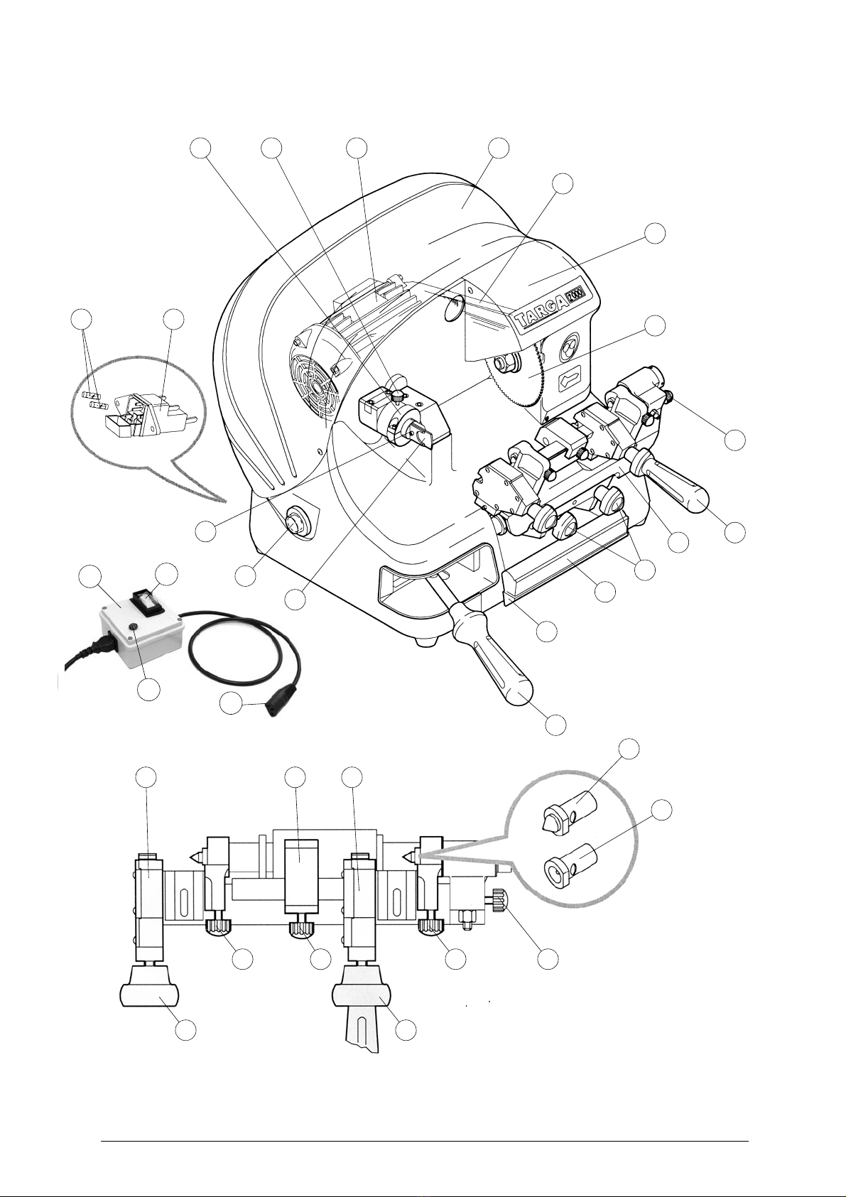
3 MACHINE DESCRIPTION
TARGA 2000 is a professional machine for the cutting of male and female bit and double bit keys.
The main parts of the machine are described below:
• SAFETY DEVICE
Device connected to a power point with a differential switch; power the key-cutting machine by
pressing the switch (X1).
The warning light (X2) illuminates to indicate voltage in the plug (X3).
ATTENTION: switch (X1) is electromagnetic, in the event of a power failure it goes out automatically.
When electricity is restored it must be reset manually to power the machine again by
means of the plug (X3).
• MOTOR MASTER SWITCH
The motor button (N) is placed on the left side of the TARGA 2000 key-cutting machine.
ATTENTION: the switch is constantly illuminated to indicate that the machine is live.
• MOTOR AND TRANSMISSION UNIT
Transmission to the motor is driven by abelt which activates the cutting tool. The transmission unit
is protected by two protective covers:
- cutting tool cover (L1),
- motor cover (M1).
• CLAMP CARRIAGE
The clamp carriage (D) comprises two clamps (E) for the cutting of bit and double bit keys. The
carriage moves horizontally by means of lever (A). The carriage handle (B) is used for rounding off
the key cuts. The key-cutting machine has a slopingtable to channel chippings into the special tray
(C) situated under the carriage and easily removed for cleaning.
• CUTTING UNIT
The cutting unit contains the working parts of the TARGA 2000 key-cutting machine, which work in
unison to read and duplicate original keys, and carry out the necessary finishing operations.
The working parts are listed below:
-Cutting tool: the cutting tool (L) is the part of the TARGA 2000 machine which cuts male and
female bit and double bit keys. The tool is in HSS super rapid steel and is protected by a spe-
cial cover (L1) to ensure safe operation.
-Tracer point: the tracer point (I) reads the profiles of male and female bit and double bit keys
and is housed on the left-hand side of the machine base. Cutting depth and pitch are easily
regulated. Its spring facilitates and speeds up cutting as it guides the operator’s movements
accurately and precisely.
-Clamps for male and female bit and double bit keys: the clamps (E) have two jaws which
ensure perfect grip on the stems of male and female bit and double bit keys.
-Bit and double bit key clamp knobs: the two jaws are locked in place by two anatomically
shaped knobs (E1) which ensure a perfect grip on the key.
-Male and female centring devices: the jaws also hold the male (G) and female (G1) centring
devices for aligning and centring the keys.
-Centring device knobs: two anatomically shaped knobs (G2) lock and release the centring
device to avoid vibrations during the key cutting operations.
-Head stop: situated on the carriage in the same position as the right-hand jaw, the head stop
(H) helps to secure the keys during the cutting operation. It can be regulated according to the
length of the key by releasing the knob (H1).