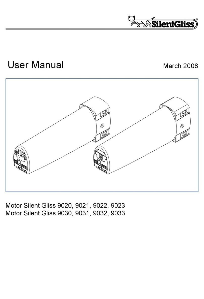
Silent Gliss 20 Series User manual

Rohrmotor 20er Serie
DE
Montage
Befolgen Sie die nachfolgenden Montagehinweise!
–
Der Antrieb muss so befestigt werden, dass er
keine Gefahr für Personen darstellt.
– Bevor der Rohrmotor installiert wird, müssen alle
nicht benötigten Leitungen und Einrichtungen, die
für den Betrieb nicht erforderlich sind, entfernt
werden.
– Bei der Installation, beim Betrieb und wenn
Arbeiten am System durchgeführt werden,
muss die Möglichkeit einer allpoligen Trennung
vom Netz bestehen (ein zweipoliger Schalter mit
min. 3 mm Kontaktöffnungsweite oder allpoliger
Hauptschalter).
– Wird der Rohrmotor mit einem Schalter mit
AUS-Voreinstellung (Totmann) gesteuert, muss
der Taster über 1,50 m Höhe angebracht werden
und von den beweglichen Teilen getrennt sein.
Der Fahrbereich der Systeme muss während des
Betriebs einsehbar sein.
– Bewegliche Teile in einem Rohrmotor müssen
unterhalb 2,5 m geschützt werden.
– Bemessungs-Drehmoment und Bemessungs-
Betriebsdauer müssen auf die Anforderungen
des angetriebenen Produkts angestimmt sein.
– Bitte beachten Sie die technischen Daten auf
dem Typenschild.
– Beachten Sie, dass bei diesem Rohrmotor
(Typ S und M Rohrmotoren) der kleinste
Rohrinnendurchmesser 36 mm und 46 mm
entspricht.
– Der Rohrmotor darf nur so eingebaut werden,
dass er nicht beregnet wird.
– Rohrmotor nicht in explosionsgefährdeter
Umgebung oder in mobile Einrichtungen
(z. B. Fahrzeuge) einbauen.
– Halten Sie Kinder von (Fern-)Steuerungen fern.
Beachten Sie vor der Montage:
• Der Rohrmotor ist nur in eingebautem Zustand funktionsfähig.
• Anschluss nur im spannungsfreien Zustand.
• Der Behang muss auf der Wickelwelle befestigt werden.
• Das Profilrohr muss genug Abstand zum Motorrohr aufweisen.
• Achten Sie auf ein axiales Spiel (1–2 mm)
Gerätefunktionen:
• Behangschutz (Drehmomentabschaltung)
• Inbetriebnahme des Rohrmotors mit Montagekabel
Auslieferzustand (Inbetriebnahmemodus)
• Einstellen der Endlagen
Warnung!
Bewahren Sie die Anleitung auf!
Nach Einbau des Rohrmotors diese Montageanleitung
für den Elektriker am Kabel befestigen.
Entfernen des Gerätesteckers
Verletzungsgefahr durch
Stromschlag.
Bei ausgestecktem Geräte-
stecker muss die Motorleitung
spannungsfrei sein.
Gerätestecker entfernen
Motorleitung spannungsfrei schalten.
1. Mit Schraubendreher Verriegelung des Gerätesteckers zur
Leitung hin drücken.
2. Stecker abziehen.
Gerätestecker einführen
3.
Stecker spannungsfrei einführen, bis Verriegelung einrastet.
Lieferzustand Stecker einführenStecker entfernen
Warnung!
3
1
2
Warnung!
Wichtige Sicherheitshinweise!
Befolgen Sie nachfolgende Anweisungen.
Verletzungsgefahr durch Stromschlag.
Anschlüsse am 230 V Netz müssen durch eine
autorisierte Fachkraft erfolgen.
Prüfen Sie die Anlage (System) regelmäßig auf
Verschleiß oder Beschädigungen.
Die Vorschriften der örtlichen Energieversorgungs-
unternehmen, sowie die Bestimmungen für nasse
und feuchte Räume nach VDE 0100, sind beim
Anschluss einzuhalten.
Verwenden Sie nur unveränderte Originalteile.
Nicht im Bereich des Rohrmotors bohren!
Halten Sie Personen solange von der Anlage fern,
bis diese still steht.
Bei Arbeiten am System (Wartung, Fenster putzen)
trennen Sie stets das System vom Versorgungsnetz.
DE

Anschluss/Einbau/Inbetriebnahme
2
Sie können jetzt die Endlagen mit dem Montagekabel einstellen.
Bitte beachten Sie: Drücken Sie eine der Fahrtasten so
lange, bis der Rohrmotor durch einen
kurzen, automatischen STOPP den
Übergang in den Programmiermodus
signalisiert.
Sie können jetzt die Endlagen einstellen.
Hinweis: Der Behangschutz ist erst nach einer vollständigen,
ununterbrochenen Auf- und Abfahrt an den Behang
angepasst.
Anschlussbeispiel Rohrmotor 230 V/50 Hz
Anschluss für Montagekabel
2. Netz einschalten.
Hinweis: Sie können mehrere Rohrmotoren der 20er Serie
parallel anschließen. Beachten Sie dabei die maximale
Schaltleistung der Schaltstelle.
Hinweis:
Die Motor-
ansteuerungen in
Auf-/Ab-Richtung
müssen gegen-
einander verriegelt
sein.
Es ist eine Umschalt-
verzögerung von
mindestens 0,5 Sek.
zu gewährleisten.
schwarz
PE
N
L1
102
Netz 230V/50Hz
Schalterdose
Abzweigdose
Jalousieschalter
oder -taster
braun
blau
grün/gelb
Wicklungsthermostat
Elektronik
Kondensator
Gerätestecker
Inbetriebnahme
Hinweis: Der Rohrmotor befindet sich bei der Auslieferung im
Inbetriebnahmemodus.
3
2
1
3
2
1
elero
Blau (Neutralleiter) (1)
Schwarz (2)
Braun (3)
Grün-gelb
Netz
1.

3
Obere/untere Endlage frei einstellbar
Obere/untere Endlage frei einstellbar
1. Fahren Sie den Behang ca. 5 cm vor die gewünschte obere
Endlage.
Der Rohrmotor fährt mit einem kurzen STOPP los.
3. Drücken Sie solange die AB-Taste, bis der Rohrmotor
automatisch stoppt.
Die obere Endlage ist eingestellt.
5. Fahren Sie die gewünschte untere Endlage an.
Korrekturen sind über die Tasten möglich.
Hinweis: Beachten Sie den richtigen Anschluss.
6. Drücken Sie solange die AUF-Taste, bis der Rohrmotor
automatisch stoppt.
Die untere Endlage ist eingestellt.
Die Endlageneinstellung ist abgeschlossen.
2. Drücken Sie erneut die AUF-Taste.
Fahren Sie die gewünschte obere Endlage an.
Korrekturen sind über die Tasten möglich.
4. Drücken Sie erneut die AB-Taste.
Fahren Sie den Behang bis kurz vor die gewünschte untere
Endlage.
Der Rohrmotor fährt mit einem kurzen STOPP los.
STOPP
STOPP
STOPP
STOPP
DE

Ändern/Löschen der Endlagen
Fehlersuche
3
2
1
3
2
1
Netz
Ändern/Löschen der Endlagen
1. Netz einschalten.
2. Fahren Sie den Behang in eine Mittelposition.
elero
Blau (Neutralleiter) (1)
Schwarz (2)
Braun (3)
Grün-gelb
ca.
5 Sek.
3. Drücken Sie gleichzeitig beide Tasten am Montagekabel.
Der Rohrmotor fährt nach ca. 5 Sek. kurz auf und ab.
Damit ist die Löschung der Endlagen abgeschlossen.
Sie können jetzt die Endlagen neu einstellen.
Fehler Mögliche Ursache Behebung
• Rohrmotor stoppt während • Endlagen sind nicht eingestellt • Endlagen einstellen
einer Fahrbewegung • Rohrmotor befindet sich im Einstellmodus
• Rohrmotor bleibt nach kurzer • Endlage wurde gespeichert • Zweite Endlage einstellen
Fahrt stehen • Schwergängiges System • Leichtgängigkeit des Systems prüfen
• Rohrmotor fährt nur in • Anschlussfehler • Anschluss überprüfen
einer Richtung
• Rohrmotor reagiert nicht • Keine Netzspannung • Netzspannung überprüfen
• Thermostat hat ausgelöst • Antrieb abkühlen lassen
• Rohrmotor lernt keine • Zufällige Fahrbewegung • Endlagen löschen
Endlagen ein Endlagen neu einstellen
• Fahrweg zur Endlage/Anschlag zu kurz • Rohrmotor muss bis zum kurzen
STOPP fahren
Fehlersuche
13 Technische Änderungen vorbehalten

GB
Tubular motor – 20 series
Warning!
Warning!
Delivery condition Insert plugRemove plug
Warning!
3
1
2
Remove the motor cable plug
Switch off voltage supply.
1. Press locking mechanism on the plug towards the cable using a
screwdriver.
2. Pull out the plug.
Insert the motor cable plug
3.
Switch off voltage supply. Insert plug until locking mechanism
engages.
Remove of the motor cable plug
Risk of injury due to
electrocution.
When the motor cable plug
is removed the supply line
must be volt free.
Installation
Observe the following installation instructions!
–
The tubular motor must be fixed in such a way that
it does not endanger personnel.
– Before installing the
tubular motor
, all lines and
equipment, which are not required for operation,
must be removed from the site.
– During installation, during operation and when
work is carried out on the system, the option to
separate all three poles from the mains must
always exist (a two-pole switch with minimum
3 mm contact gap or all-pole main switch).
– If the
tubular motor
is controlled by a switch with
OFF pre-setting (dead man’s button), the
momentary contact switch must be fitted at a
height of more than 1.50 m and separated from
the moving parts.
The travel range of the systems must always be
visible during operation.
– Moving parts in a
tubular motor
, which are below
2.5 m, must be guarded.
– Set torque and set operating time must be
adapted to the requirements of the product which
is driven.
– Please note the technical data on the type plate.
– Please note that with this
tubular motor
(type S
and M tubular motors) the smallest internal tube
diameter corresponds with 46 mm.
– The
tubular motor
must be installed so that it
cannot get wet.
– Do not install
tubular motor
in surroundings which
are at risk of explosion or in mobile appliances
(e.g. motor vehicles).
– Keep children away from the (remote) control unit.
Keep these instructions in a safe place!
After installation of the tubular motor attach these
instructions to the cable for the electrician.
Device functions:
• Blind protection (torque limiting)
• Commissioning the tubular motor with the assembly cable.
As-delivered condition (commissioning mode)
• Setting end positions
Important safety instructions!
Observe the following instructions.
Risk of injury due to electrocution.
The connections to the 230 V mains must be
made by authorised specialist personnel.
Check the system regularly for wear or damage.
The regulations of the local energy supply company
as well as the regulations for wet and damp rooms
according to VDE 0100 must be followed when
making the connections.
Only use unmodified original electrical parts.
Do not drill in the area of the tubular motor!
Keep people away from the system until it is
stationary.
When working on the system (servicing, cleaning
windows etc.), always disconnect the system from
the mains supply.
Check the following before installation:
• The tubular motor is only capable of operation as installed.
• Only perform connecting work with the power turned off.
• The blind must be attached to the winding shaft.
• The profile tube must have sufficient clearance from the motor
tube.
• Make sure there is sufficient axial play (1–2 mm)
GB

Connection/Installation/Commissioning
2
Assembly cable connection
2. Switch on mains.
Note:
The motor controls
in up/down direction
must be locked
against each other.
A reversing delay of
at least 0,5 sec.
must be ensured.
black
PE
N
L1
102
brown
blue
green/yellow
Condenser
Electronics
interlocked push
button or
momentary
contact switch
Mains 230V/50 Hz
Winding thermostat
Switch box
Motor cable plug
Junction box
Start up
Note: The tubular motor is in commissioning mode when the
–roller shutters are delivered.
3
2
1
3
2
1
elero
Blue (neutral wire) (1)
Black (2)
Brown (3)
Green-yellow
Mains
1.
Connection example, tubular motor – 20 series
230 V/50 Hz
Note: You can connect several tubular motors – 20 series in
parallel.
Please note the maximum control capacity of the control
unit.
You can now set the end positions with the assembly cable.
Please note: Press the travel key until the tubular motor
signals the transition into the programming
mode, by a short automatic STOP.
You can now program the end positions.
Note: The blind protection system is only adapted to the blind
after a complete, uninterrupted upwards and downwards
travel.

3
Upper/lower limit position freely programmable
Upper/lower limit position freely programmable
5. Travel to the desired lower limit stop.
It is possible to make corrections using the momentary
contact switches.
Note: Ensure that the equipment is correctly connected.
2. Press the UP momentary contact switch again.
Go to the desired upper end position.
It is possible to make corrections using the momentary
contact switches.
STOP
STOP
STOP
STOP
1. Move the blind up to approx. 5 cm before the desired upper
limit stop.
The tubular motor starts up slowly with a short STOP.
3. Press the DOWN momentary contact switch until the tubular
motor stops automatically.
The upper limit stop is programmed.
6. Press the UP momentary contact switch until the tubular
motor stops automatically.
The lower limit has been set.
Setting of the end positions is now complete.
4. Press the DOWN momentary contact switch again.
Move the blind down until it is a short distance above the
desired lower limit stop.
The tubular motor starts up slowly with a short STOP.
GB

Changing/Deleting the limit positions
Troubleshooting
3
2
1
3
2
1
Mains
Changing/Deleting the limit positions
1. Switch on mains.
2. Move the blind to an intermediate position.
elero
Blue (neutral wire) (1)
Black (2)
Brown (3)
Green-yellow
approx.
5 sec.
Troubleshooting
We reserve the right to make technical changes
3. Press both momentary contact switches on the assembly cable
simultaneously.
The tubular motor travels up and down briefly after approx. 5
seconds.
Deletion of the limit positions is complete.
You can now re-programme the limit positions.
Fault Possible cause Remedy
• Tubular motor stops during • Limit positions are not set • Set limit positions
travel • Tubular motor is in setting mode
• Tubular motor stops after • End position programmed • Set second limit position
short travel • System stiff • Check smooth running of the system
• Tubular motor runs only in • Faulty connection • Check connection
one direction
• Tubular motor does not react • No power supply • Check mains voltage
• Thermostat has triggered • Allow drive to cool down
• Tubular motor does not learn • Random travel • Delete limit positions
in limit positions Re-programme limit positions
• Travel to limit position/stop too short • Tubular motor has to travel to short STOP

FR
Moteur tubulaire série 20
Attention !
Attention !
Déconnexion de la prise
Danger de blessure par
électrocution.
Lorsque la fiche est
déconnectée, le câble
d’alimentation doit être
hors tension.
État de livraison Connexion
de la fiche
Déconnexion
de la fiche
Attention !
3
1
2
Conservez ces instructions !
Après avoir installé le moteur tubulaire, veuillez accrocher
les présentes instructions de montage au câble à l’attention
de l’électricien.
Fonctions de l’appareil :
• Protection de tablier (coupure de couple)
• Mise en service du moteur tubulaire à l’aide du boîtier de pro-
grammation
État à la livraison (mode de mise en service)
• Réglage des positions finales
Consignes de sécurité importantes !
Veuillez respecter les instructions suivantes.
Danger de blessure par électrocution.
Les connexions au réseau 230 V doivent être
effectuées par un spécialiste autorisé.
Contrôlez régulièrement l’installation en vue d’une
éventuelle usure ou d’endommagements.
Lors du raccordement, il convient de respecter les
prescriptions des entreprises de distribution
d'électricité locales, ainsi que les directives pour
locaux mouillés et humides selon VDE 0100.
Utilisez exclusivement des pièces d’origine.
Ne pas forer à proximité du moteur tubulaire !
Tenez les personnes à distance de l’installation
tant que celle-ci n’est pas à l’arrêt.
Avant d’intervenir sur l’installation (maintenance,
nettoyage des fenêtres), débranchez systématique-
ment l’installation du réseau d’alimentation.
Observez avant le montage :
•
Le moteur tubulaire n’est fonctionnel que lorsqu’il est entièrement
installé.
• Raccordement uniquement lorsque l’installation est hors tension.
• Le tablier doit être fixé à l’arbre d’enroulement.
• Le tube profilé doit présenter une distance suffisante par rapport
au tube du moteur.
• Veuillez tenir compte d’un jeu axial de 1 à 2 mm.
Montage
Veuillez suivre les instructions de montage
suivantes !
–
Le moteur tubulaire doit être fixé de manière à ce
qu’il ne représente aucun danger pour les
personnes.
– Avant que le moteur tubulaire ne soit installé,
toutes les conduites et tous les équipements qui
ne sont pas nécessaires à son fonctionnement
doivent être enlevés.
– Lors de l’installation, du fonctionnement et en
cas d’intervention sur l’installation, une possibi-
lité de séparation du réseau (sur tous les pôles)
doit exister (fiches Hirschmann mâle et femelle
ou un interrupteur bipolaire avec ouverture de
contact minimale de 3 mm, ou un interrupteur
principal à coupure sur tous les pôles).
– Si le moteur tubulaire est commandé par un
interrupteur avec position de coupure préréglée
(version homme mort), l’interrupteur doit être
installé au-dessus de 1,50 m et séparé des
pièces mobiles.
La plage d’action des installations doit rester
visible pendant le fonctionnement.
– Les pièces mobiles d’un moteur tubulaire doivent
être protégées au-dessous de 2,5 m.
– Le couple assigné et la durée de fonctionnement
assignée doivent être adaptés aux exigences du
produit actionné par le moteur.
Veuillez respecter les caractéristiques techni-
ques figurant sur la plaque signalétique.
– Veuillez noter que pour ce moteur (moteurs
tubulaires type S ou M), le plus petit diamètre
intérieur de tube est de 36 mm ou 46 mm.
– Le moteur tubulaire doit être installé à l’abri des
intempéries.
– Les moteurs tubulaires ne peuvent pas être
installés dans un environnement explosif ou dans
des équipements mobiles (p. ex. véhicules).
– Gardez les enfants éloignés des
(télé)commandes.
Déconnexion de la fiche
Mettre le câble d’alimentation hors tension.
1. Pousser le verrouillage de la fiche vers le câble à l’aide d’un
tournevis.
2. Déconnecter la fiche.
Connexion de la fiche
3.
Insérer la fiche (hors tension) jusqu’à ce que le verrouillage
s’enclenche
.
FR

Raccordement/Montage/Mise en service
2
Raccordement pour boîtier de programmation
2. Raccorder au réseau.
Mise en service
3
2
1
3
2
1
elero
Bleu (conducteur neutre) (1)
Noir (2)
Brun (3)
vert-jaune
Réseau
1.
Remarque :
Les commandes
du moteur pour les
directions montée
et descente
doivent être
verrouillées
réciproquement.
Il est nécessaire
d'assurer une
temporisation
de 0,5 sec. au
minimum entre
chaque inversion
du sens de
rotation.
noir
PE
N
L1
102
brun
bleu
vert/jaune
Condensateur
Électronique
Inverseur ou
bouton poussoir
Réseau 230V/50 Hz
Thermostat
Boîte d’interrupteur
Boîte de dérivation
Fiche
Exemple de branchement moteur tubulaire Série 20
230 V/50 Hz
Remarque : Il est possible de raccorder plusieurs moteurs
tubulaires série 20 en parallèle. Respectez à cet
égard le pouvoir de coupure maximum du point de
liaison.
Vous pouvez régler maintenant les positions finales à l’aide du
câble de montage.
Veuillez observer : Appuyez sur l’une des touches de
déplacement jusqu’à ce que le moteur
tubulaire signale le passage dans le mode
de programmation par un bref ARRET
automatique.
Vous pouvez maintenant programmer les
positions finales.
Remarque : La protection du tablier ne s’adapte à ce dernier
qu’après un déplacement complet et ininterrompu
vers le haut et vers le bas.
Remarque : À la livraison, le moteur tubulaire est en mode de
mise en service.

3
Position finale supérieure/inférieure réglable au gré
Position finale supérieure/inférieure réglable au gré
5. Faites tourner le moteur jusqu’à la position finale inférieure
souhaitée.
Des corrections sont possibles par le biais des touches.
Remarque : Veuillez respectez le raccordement correct.
2. Appuyez à nouveau sur la touche MONTÉE.
Faites tourner le moteur jusqu’à la position finale supérieure
souhaitée.
Des corrections sont possibles par le biais des touche
STOP
STOP
STOP
STOP
3. Maintenez la touche DESCENTE enfoncée jusqu’à ce que le
moteur tubulaire s’arrête automatiquement.
La position finale supérieure est réglée.
1. Déplacez le tablier jusqu’à environ 5 cm avant la position
finale supérieure souhaitée.
Le moteur tubulaire démarre lentement avec un bref ARRÊT.
4. Appuyez à nouveau sur la touche DESCENTE.
Déplacez le tablier jusqu’à peu avant la position finale
inférieure souhaitée.
Le moteur tubulaire démarre lentement avec un bref ARRÊT.
6. Maintenez la touche MONTÉE enfoncée jusqu’à ce que le
moteur tubulaire s’arrête automatiquement.
La position finale inférieure est réglée.
Le réglage des positions finales est terminé.
FR

Modifier/Effacer les positions finales
Dépannage
3
2
1
3
2
1
Réseau
Modifier/Effacer les positions finales
1. Raccorder au réseau.
2. Déplacez le tablier en une position centrale.
elero
Bleu (conducteur neutre) (1)
Noir (2)
Brun (3)
vert-jaune
pendant
env. 5
secondes
Dépannage
Sous réserve de modifications techniques
3. Appuyez simultanément sur les deux touches du boîtier de
programmation.
Le moteur tubulaire se déplace vers le haut et le bas pendant
env. 5 sec.
Ceci clôture l’effacement des positions finales.
Vous pouvez maintenant programmer à nouveau les positions
finales.
Dérangement Cause possible Suppression
• Le moteur tubulaire s’arrête • Les positions finales ne sont pas réglées • Réglez les positions finales
durant un déplacement • Le moteur tubulaire se trouve en mode de
réglage
• Le moteur tubulaire s'arrête • Une position finale a été enregistrée • Programmez la seconde position finale
après un bref déplacement • Le tablier est grippé • Vérifiez le fonctionnement sans accrocs
du tablier
• Le moteur tubulaire ne se • Erreur de raccordement • Vérifiez le raccordement
déplace que dans un sens
• Le moteur tubulaire ne réagit • Pas de tension réseau • Vérifiez la tension réseau
pas • Le thermostat s’est déclenché • Laissez refroidir le moteur
• Le moteur tubulaire n’apprend • Mouvement de déplacement arbitraire • Effacez les positions finales
pas les positions finales Réglez à nouveau les positions finales
• Course trop brève jusqu’à la position finale/ • Le moteur tubulaire doit se déplacer
la butée jusqu’à un bref ARRÊT

IT
Motore tubolare serie 20
Avvertenza!
Avvertenza!
Stato alla
consegna Inserimento dello
spinotto
Rimozione dello
spinotto
Avvertenza!
3
1
2
Conservare le presenti istruzioni!
Dopo aver montato il motore tubolare, fissare le presenti
istruzioni al cavo per il tecnico elettricista.
Funzioni del dispositivo:
• Protezione telo (disinserzione coppia)
• Messa in esercizio del motore tubolare con cavo prova
Stato alla consegna (modalità di messa in esercizio)
• Impostazione delle posizioni di finecorsa
Importanti norme di sicurezza!
Osservare le seguenti istruzioni.
Pericolo di lesioni dovute ad elettroconduzione.
Gli allacciamenti alla rete a 230 V devono essere
effettuati da un elettricista autorizzato.
Controllare regolarmente se l’impianto è usurato o
danneggiato.
Per l’allacciamento osservare scrupolosamente le
prescrizioni delle aziende locali fornitrici di energia
e le norme VDE 0100 per l’installazione in ambienti
bagnati ed umidi.
Usare solo componenti integri originali.
Non praticare fori nella zona del motore tubolare!
Tenere lontano le persone estranee dall’impianto
fino al completo arresto di quest’ultimo.
Prima di eseguire qualsiasi intervento sull’impianto
(manutenzione, pulizia delle finestre), scollegarlo
sempre dalla rete di alimentazione elettrica.
Prima del montaggio ricordarsi quanto segue:
• Il motore tubolare funziona solo quando è montato.
• Provvedere all’allacciamento solo dopo aver tolto la tensione.
• Il telo va fissato al tubo avvolgitore.
• Il tubo profilato non deve assolutamente toccare il tubo del
motore.
• Accertarsi che ci sia un minimo gioco assiale (1-2 mm)
Montaggio
Osservare le seguenti istruzioni di montaggio!
– Il motore tubolare deve essere fissato in modo
che non costituisca pericolo per le persone.
– Prima di installare il motore tubolare è
necessario rimuovere tutti i cavi e gli apparecchi
non necessari per il funzionamento.
– Durante l’installazione, il funzionamento e gli
eventuali interventi sull’impianto, è necessario
prevedere una separazione onnipolare dalla rete
elettrica (o interruttore bipolare con apertura
minima dei contatti di 3 mm o interruttore
generale onnipolare).
– Se il motore tubolare viene azionato a mezzo di
un interruttore con preimpostazione OFF (uomo
presente), il pulsante deve essere installato ad
un’altezza di 1,50 m e separato dalle parti mobili.
La zona di corsa degli impianti deve poter essere
osservata durante il funzionamento.
– Le parti mobili di un motore tubolare ad un’altezza
inferiore a 2,5 m devono essere protette.
– La coppia e la durata di funzionamento nominali
devono essere adeguate ai requisiti del prodotto
azionato dal motore.
– Si prega di osservare i dati tecnici riportati sulla
targhetta.
– Tenere presente che per questo motore tubolare
(motori tubolari di tipo S e M), il diametro interno
minimo del tubo è pari a 36 mm e 46 mm.
– Il motore tubolare deve essere installato in modo
tale che non risulti esposto alla pioggia.
– Non montare i motori tubolari in ambienti a
rischio di esplosione o in unità mobili (ad
esempio all’interno di veicoli).
– Tenere lontano i bambini dai (tele)comandi.
Rimozione dello spinotto del dispositivo
Pericolo di lesioni per
elettroconduzione.
Se lo spinotto del dispositivo
non è collegato, il cavo di
alimentazione deve essere
esente da tensione.
Rimozione dello spinotto del dispositivo
Levare la tensione dal cavo di alimentazione.
1.
Spingere con un cacciavite la sicura dello spinotto verso il cavo.
2. Estrarre lo spinotto.
Inserimento dello spinotto
3. Inserire lo spinotto in assenza di tensione, fino a quando la
sicura scatta.
IT

Collegamento/Installazione/Messa in esercizio
2
Collegamento per cavo di montaggio
2. Dare tensione.
Messa in esercizio
3
2
1
3
2
1
elero
Blu (Neutro) (1)
Nero (2)
Marrone (3)
Verde
Rete
1.
Esempio di collegamento motore tubolare serie 20
230 V/50 Hz
Avvertenza:
i sistemi di comando
del motore per le
direzioni di
SALITA/DISCESA
devono esser
interbloccati.
Deve essere
garantito un ritardo
di commutazione di
almeno 0,5 secondi.
PE
N
L1
102
Condensatore
Elettronica
Interruttore
o tasto
Rete 230V/50 Hz
Termostato ad
avvolgimento
Scatola
interruttore
Scatola di
derivazione
Spinotto
(esterna al
cassonetto)
nero
marrone
blu
verde/
giallo
Avvertenza: è possibile collegare in parallelo più motore
tubolare serie 20. In tal caso, tenere conto della
porata massima dell'interruttore di comando.
Avvertenza: al momento della consegna, il motore tubolare è
impostato sulla modalità di messa in esercizio.
Ora è possibile regolare le posizioni di finecorsa con il cavo di
montaggio.
Osservare quanto segue: ogni movimento interrotto da un
breve arresto segnala che il
motore tubolare è in modalità di
regolazione.
Avvertenza: la protezione telo si adatta perfettamente solo
dopo che la tapparella è stata sollevata e
riabbassata completamente almeno una volta,
senza interruzioni.

3
Posizione di finecorsa superiore/inferiore regolabile a piacere
Posizione di finecorsa superiore/inferiore regolabile
a piacere
5. Abbassare la tenda fino alla posizione di finecorsa inferiore
desiderata.
I pulsanti consentono di correggere l’impostazione.
Avvertenza: accertarsi che il collegamento sia corretto
2. Premere di nuovo il pulsante di SALITA.
Sollevare la tenda fino alla posizione di finecorsa superiore
desiderata.
I pulsanti consentono di correggere l’impostazione.
STOP
STOP
STOP
STOP
1. Sollevare la tenda fino a circa 5 cm dalla posizione di finecor-
sa superiore desiderata.
Il motore tubolare parte lentamente, con un breve STOP, per
poi diventare più veloce.
3. Premere il pulsante di DISCESA, fino a quando il motore
tubolare non si arresta automaticamente.
La posizione di finecorsa superiore è impostata.
4. Premere di nuovo il pulsante di DISCESA.
Portare il telo vicino alla posizione di finecorsa inferiore
desiderata.
Il motore tubolare parte lentamente, con un breve STOP, per
poi diventare più veloce.
6. Premere il pulsante di SALITA, fino a quando il motore
tubolare non si arresta automaticamente.
La posizione di finecorsa inferiore è impostata.
L’impostazione delle posizioni di finecorsa è terminata.
IT

Modifica/cancellazione delle posizioni di finecorsa
Ricerca dei guasti
3
2
1
3
2
1
Rete
Modifica/cancellazione delle posizioni di finecorsa
1. Dare tensione.
2. Portare la tenda in una posizione centrale.
elero
Blu (Neutro) (1)
Nero (2)
Marrone (3)
Verde
ca.
5 sec.
Ricerca dei guasti
Ci riserviamo variazioni tecniche
3. Premere contemporaneamente i due pulsanti sul cavo di
montaggio.
Dopo circa 5 secondi il motore tubolare comanda un breve
movimento di salita ed uno di discesa.
In questo modo la cancellazione delle posizioni di finecorsa è
terminata.
A questo punto è possibile reimpostare le posizioni di
finecorsa.
Problema Possibile causa Rimedio
• Il motore tubolare si arresta • Le posizioni di finecorsa non sono impostate • Impostare le posizioni di finecorsa
durante un movimento • Il motore tubolare è impostato in modalità
regolazione
• Il motore tubolare si arresta • La posizione di finecorsa è stata memorizzata • Impostare la seconda posizione di finecorsa
dopo un breve movimento • La telo si muove con difficoltà • Controllare la scorrevolezza della telo
• Il motore tubolare funziona • Errore di collegamento • Controllare il collegamento
solo in una direzione
• Il motore tubolare non • Assenza di tensione di rete • Controllare la tensione di rete
reagisce • La termica è scattata • Far raffreddare il motore
• Il motore tubolare non • Movimenti casuali • Cancellare le posizioni di finecorsa
memorizza le posizioni di Reimpostare le posizioni di finecorsa
finecorsa • La distanza fino alla posizione di finecorsa/ • Il motore tubolare deve funzionare fino a
battuta è troppo breve raggiungere il breve STOP

IT


IT

13 816.6001
08/09
Silent Gliss International
Australia
Silent Gliss Pty Ltd.
483 Balmain Road
Lilyfield NSW 2040
Australia
Phone: 0061 2 981043 00
Fax: 0061 2 981043 11
www.silentgliss.com.au
Italia
Silent Gliss Italia Srl.
Via Reggio Emilia 33
20090 Redecesio di Segrate/
Milano
Italia
Phone: 0039 02 26 903 903
Fax: 0039 02 21 332 88
www.silentgliss.it
Japan
Silent Gliss Cooperation
4F Sanko Bldg.
No. 28 Sakamachi, Shinjuku-ku
Tokyo, 160 – 0002
Japan
Phone: 0081 3 33 50 48 09
Fax: 0081 3 33 50 43 34
www.silentgliss.co.jp
Netherland
Silent Gliss Benelux
Westzijde 168c
1506 EK Zaandam
Netherland
Phone: 0031 75 612 7800
Fax 0031 75 612 7810
www.silentgliss.nl
Norway
Norsk Silent Gliss A/S
Slomarka Naeringsomraade
2100 Skarnes
Norway
Phone: 0047 62 96 62 22
Fax 0047 62 96 62 23
www.silentgliss.no
Switzerland
Silent Gliss AG
Südstrasse 1
3250 Lyss
Switzerland
Phone: 0041 32 387 1111
Fax: 0041 32 387 1140
www.silentgliss.ch
USA
Silent Gliss USA Inc.
1850 Beaver Ridge Circle,
Suite A
Norcross, GA 30071
USA
Phone: 001 770 466 48 11
Fax: 001 770 466 48 14
www.silentgliss-usa.com
Austria
Silent Gliss GesmbH
Gewerbestrasse 6
6710 Nenzing Beschling
Austria
Phone: 0043 5525 64111
Fax: 0043 5525 63170
www.silentgliss.at
Belgium
Silent Gliss Benelux
Hector Henneaulaan 101
1930 Zaventem
Belgium
Phone: 0032 2 240 036 0
Fax: 0032 2 240 036 9
www.silentgliss.be
China
Silent Gliss Window
Treatment (SH) Co. Ltd.
No. 16 of Phase 1,
Block 55 West Area
No. 588 Yindu Road
Ming Hang District
Shanghai 200030
China
Phone: 0086 21 5208 0869
Phone: 0086 21 5208 0876
Fax: 0086 21 5208 0879
www.silentgliss.cn
France
Silent Gliss S.A.S.
Parc d’Activité des Petits
Carreaux
3 ave des Marroniers
94386 Bonneuil sur Marne,
Cedex
France
Phone: 0033 1 4339 66 66
Fax: 0033 1 4339 01 20
www.silentgliss.fr
Sweden
Silent Gliss AB
Travbanegatan 9
Box 9000
SE-200 39 Malmö
Phone: 0046 40 55 52 50
Fax: 0046 40 22 15 82
www.silentgliss.se
Finland
Oy Silent Gliss Ab
Ruosilantie 18A
P.O. Box 17
FIN-00391 Helsinki
Phone: 00358 9 2515 990
Fax: 00358 9 2515 9950
www.silentgliss.fi
Germany
Silent Gliss GmbH
Rebgartenweg 5
79576 Weil am Rhein
Germany
Phone: 0049 7621 6607 0
Fax: 0049 7621 6607 37
www.silentgliss.de
Great Britain
Silent Gliss Ltd.
Pyramid Business Park
Poorhole Lane
Broadstairs/ Kent CT10 2PT
Great Britain
Phone: 0044 1843 863 571
Fax: 0044 1843 861 226
www.silentgliss.co.uk
For requests from any other country please refer to our website www.silentgliss.com
Table of contents
Languages:
Other Silent Gliss Engine manuals
Popular Engine manuals by other brands

RADEMACHER
RADEMACHER RolloTube Basic 2160 20 90 installation instructions

Continental Motors
Continental Motors TSI0L-550-C Operation, maintenance & installation manual

Milwaukee
Milwaukee DCM2 350 C manual
O.S. engine
O.S. engine Sirius 7 manual
Leadshine Technology
Leadshine Technology iCS Series user manual
Simple Motors
Simple Motors Kit 12 Assembly instructions
