SIMAG SV 130 User manual

Page 1
Page 1
SERVICE MANUAL
SV 130
SV 210
SV 310
SV 530
R 404 AVERSION
Electronic
modular cubers
MS 1000.24 REV. 10/2004

Page 2
Page 2
TABLE OF
CONTENTS
Table of contents 2
Specifications 3-4-5-6-7-8-9-10
FOR THE INSTALLER
Introduction 11
Storage bin 11
Standard legs 11
Important operating requirements 11
Select location 12
Storage bin 12
Ice machine 12
Stacking instructions 12
Final check list 14
FOR THE PLUMBER
Conform to all applicable codes
Water inlet 13
Drains 13
For the electrician
Electrical connections 13
START-UP
Start-up 15-16
OPERATION
Refrigeration during freeze 17
Water system 18
Refrigeration system during harvest 19
Water system 19
Control sequence 20
SERVICE SPECIFICATIONS
Component 21
Operating characteristics 21
COMPONENT DESCRIPTION
Component description 22-23
REMOVAL AND REPLACEMENT PROCEDURES 24-25
WIRING DIAGRAM
SV 130-210-310-530 air/water cooled 26
SERVICE DIAGNOSIS
Service diagnosis 27-28
MAINTENANCE & CLEANING INSTRUCTION
Icemaker 29
Ice storage bin 29
Cabinet erxterior 29
Cleaning (Icemaker) 29-30

Page 3
Page 3
SPECIFICATIONS
MODULAR CUBER SV 130
NOTE. TokeepyourModularcuberperformingat its maximum capacity, itis necessary to perform
periodic maintenance as outlined on page 29 of this manual.
ice making capacity
130
110
90
70
50
Kg.
32 °C
27 15 10
AIR COOLED MODELS
WATER TEMPERATURE
AMBIENT TEMPERATURE
°C
10
21
32
38
WATER COOLED MODELS
AMBIENT TEMPERATURE
Kg.
°C
27 21 15 10
°C
10
21
32
38
21
WATER TEMPERATURE
130
110
90
70
50 32
ICE PRODUCED PER 24 HRS
ICE PRODUCED PER 24 HRS

Page 4
Page 4
SPECIFICATIONS (CONT'D)
Accessoires
KSC 12 - Cube stacking kit
Dimensions:
HEIGHT 530 mm. (20" 6/7)
WIDTH 560 mm. (22")
DEPTH 600 mm. (23 5/8")
WEIGHT 52 Kgs.
Model Cond. unit Finish Comp. HP
SV 130 - MACHINE SPECIFICATIONS
Water req.
lt/24 HR
Model Basic
electr. amps Start
amps watts Electric power cons.
Kwhx24 HR. N. of wires Amps
Fuse
220-240/50/1
SV 130 - AS Air 190*
SV 130 - WS Water 1200*
SV 130 - AS
SV 130 - WS 4.0
3.8 20
20 750
650 18 .
15.6 3x1,5 mm210
Cubes per harvest: 132 Full
* With water at 15°C
Stainless Steel 5/8
①20 mm - WATER OUTLET
20 mm - WATER OUTLET - WATER COOLED ONLY
③3/4" GAS WATER INLET
④CORD SET
3/4" GAS
3/4" GAS
Ø 20 mm
Ø 25/32"
3/4" GAS
①
③
④

Page 5
Page 5
SPECIFICATIONS
MODULAR CUBER SV 210
NOTE. Tokeep your Modular cuber performingat its maximum capacity, itis necessary to perform
periodic maintenance as outlined on page 29 of this manual.
ice making capacity
220
200
180
160
140
120
Kg.
32 °C
27 21 15 10
AIR COOLED MODELS
WATER TEMPERATURE
AMBIENT TEMPERATURE
ICE PRODUCED PER 24 HRS.
°C
10
21
32
38
WATER COOLED MODELS
WATER TEMPERATURE
AMBIENT TEMPERATURE
ICE PRODUCED PER 24 HRS.
220
200
180
160
140
120
Kg.
32 °C
27 21 15 10
°C
10
21
32
38

Page 6
Page 6
SPECIFICATIONS (CONT'D)
Accessoires
KSC 18 - Cube stacking kit
Dimensions:
HEIGHT 530 mm. (20" 7/8)
WIDTH 800 mm. (31" 1/2)
DEPTH 600 mm. (25" 3/8)
WEIGHT 77 Kgs.
Model Cond. unit Finish Comp. HP
SV 210 - MACHINE SPECIFICATIONS
Water req.
lt/24 HR
Model Basic
electr. amps Start
amps watts Electric power cons.
Kwhx24 HR. N. of wires Amps
Fuse
220-240/50/1
SV 210 - AS Air 380*
SV 210 - WS Water 1800*
SV 210 - AS
SV 210 - WS 6
5.5 30
30 1100
1050 26.4
25.2 3x1,5 mm216
Cubes per harvest: 204 Full
* With water at 15°C
Stainless Steel 1 1/4
①20 mm - WATER OUTLET
20 mm - WATER OUTLET - WATER COOLED ONLY
③3/4" GAS WATER INLET
④CORD SET

Page 7
Page 7
SPECIFICATIONS
MODULAR CUBER SV 310
NOTE.To keep your Modularcuber performing at its maximumcapacity, it is necessary toperform
periodic maintenance as outlined on page 29 of this manual.
ice making capacity
330
300
270
240
210
180
Kg.
°C
AIR COOLED MODELS
WATER TEMPERATURE
°C
10
21
32
38
AMBIENT TEMPERATURE
ICE PRODUCED PER 24 HRS.
330
300
270
240
210
180
Kg.
°C
27 21 15 10
°C
10
21
32
38
AMBIENT TEMPERATURE
WATER TEMPERATURE
WATER COOLED MODELS
32
27 21 15 10
32

Page 8
Page 8
SV 310 - AS Air 470*
SV 310 - WS Water 3100*
SPECIFICATIONS (CONT'D)
Accessoires
KSC 25 - Cube stacking kit
Dimensions:
HEIGHT 680 mm. (26" 3/4)
WIDTH 800 mm. (31" 1/2)
DEPTH 600 mm. (23" 5/8)
WEIGHT 100 Kgs.
Model Cond. unit Finish Comp. HP
SV 310 - MACHINE SPECIFICATIONS
Water req.
lt/24 HR
Model Basic
electr. amps Start
amps watts Electric power cons.
Kwhx24 HR. N. of wires Amps
Fuse
220-240/50/1
SV 310 - AS
SV 310 - WS 9,0
8,0 49
49 1600
1500 38,4
36,0 3x1,5 mm216
Cubes per harvest: 289 Full
* With water at 15°C
Stainless Steel 2
①20 mm - WATER OUTLET
20 mm - WATER OUTLET - WATER COOLED ONLY
③3/4" GAS WATER INLET
④CORD SET

Page 9
Page 9
SPECIFICATIONS
MODULAR CUBER SV 530
NOTE. Tokeep your Modular cuber performingat its maximum capacity, itis necessary to perform
periodic maintenance as outlined on page 29 of this manual.
ice making capacity
AIR COOLED MODELS
AMBIENT TEMPERATURE
ICE PRODUCED PER 24 HRS.
WATER COOLED MODELS
AMBIENT TEMPERATURE
ICE PRODUCED PER 24 HRS.
°C
WATER TEMPERATUREWATER TEMPERATURE
550
500
450
400
350
300
Kg.
32 15 10
°C
10
21
32
38
27 21
525
500
475
450
425
400
Kg.
32 °C
27 15
°C
10
21
32
38
21 10

Page 10
Page 10
SV 530 - AS Air 720
SV 530 - WS Water 4800*
SPECIFICATIONS (CONT'D)
Accessoires
KSC 50 - Cube stacking kit
Dimensions:
HEIGHT 745 mm. (29" 5/8)
WIDTH 1078 mm. (42" 1/2)
DEPTH 564 mm. (22" 1/4)
WEIGHT 128 Kgs.
Model Cond. unit Finish Comp. HP
SV 530 - MACHINE SPECIFICATIONS
Water req.
lt/24 HR
Model
Cubes per harvest: 578 Full
* With water at 15°C
WATER INLET - WATER COOLED ONLY
①
③
④
SV 530 - AS
SV 530 - WS
Basic
electr.
400/50/3 N
amps
6.5
6.0
watts
2500
2200
Electric power cons.
Kwhx24 HR.
60
53
N. of wires
5x1,5 mm2
Amps
Fuse
16
Stainless Steel 3 3
①20 mm - WATER OUTLET
20 mm - WATER OUTLET - WATER COOLED ONLY
③3/4" GAS WATER INLET
④CORD SET

Page 11
Page 11
FOR THE INSTALLER
INTRODUCTION
Theseinstructionsprovidethespecificationsand
the step-by-step procedures for the installation,
start up and operation for the SIMAG Model
SV 130-210-310-530 Modular Cubers.
The Models SV 130-210-310-530 Modular
Cubers are quality designed, engineering and
constructed,andarethoroughlytestedicemaking
systems, providing the utmost in flexibility to fit
the needs of a particular user.
INSTALLATION NOTE: Allow 15 cm.
minimum space at sides and back for
ventilation and utility connections.
STORAGE BIN
TheSV130stackontopofSimagbinmodelR80;
the SV 210-310 stack onto SIMAG bin model
R 150 while the model SV 530 onto bin R 250.
Refrigerant R 404 A
Charge per nameplate rating.
STANDARD LEGS: Furnished with storage bin.
Fourlegsscrewintomountingsocketsoncabinet
base. Provide 16 cm. (6'’) minimum height
including adjustable leveling foot.
Optional Kit Casters for R 80 - R 150 (KRB 390)
andforR250(KRB550)areavailableonrequest.
IMPORTANT OPERATING REQUIREMENTS
MINIMUM MAXIMUM
Air Temperature 10°C(50°F) 40°C(100°F)
Water Temperature 5°C(40°F) 35°C(90°F)0
Water Pressures 1 bar gauge 5 bar gauge
Electrical Voltage
Variations Voltage
rating specified
on nameplate -10% +10%
Extended periods of operation exceeding these
limitations constitues misuse under the terms of
Manufacturer’s Limited Warranty, resulting in a
loss of warranty coverage.

Page 12
Page 12
SELECT LOCATION
The first step in installing the equipment is to
select the location. The purchaser of the unit will
have a desired spot in mind, check out that spot
to insure that it is:
- indoors,inanenvironmentthatdoesnotexceed
theairandwatertemperaturelimitationsforthe
equipment.
- thatthenecessaryutilitiesareavailableincluding
the correct voltage electrical power.
- thattherebespacearoundtheinstalledmachine
forservice,15 cm.minimumleft, right, andrear
for air-cooled models.
STORAGE BIN
The SIMAG bins for these units are the
R 80, R 150 and R 250.
Otherbins may beavailable withbin tops tovary
the storage capacity. Lay the bin on its back,
using cardboard from the carton to support it,
screw in the legs.
Stand the bin upright, and correct any possible
small tears in the machine mounting gasket with
food grade silicone sealant.
ICE MACHINE
The use of a mechanical lift is recommended for
lifting the uncrated icemaker onto the bin.
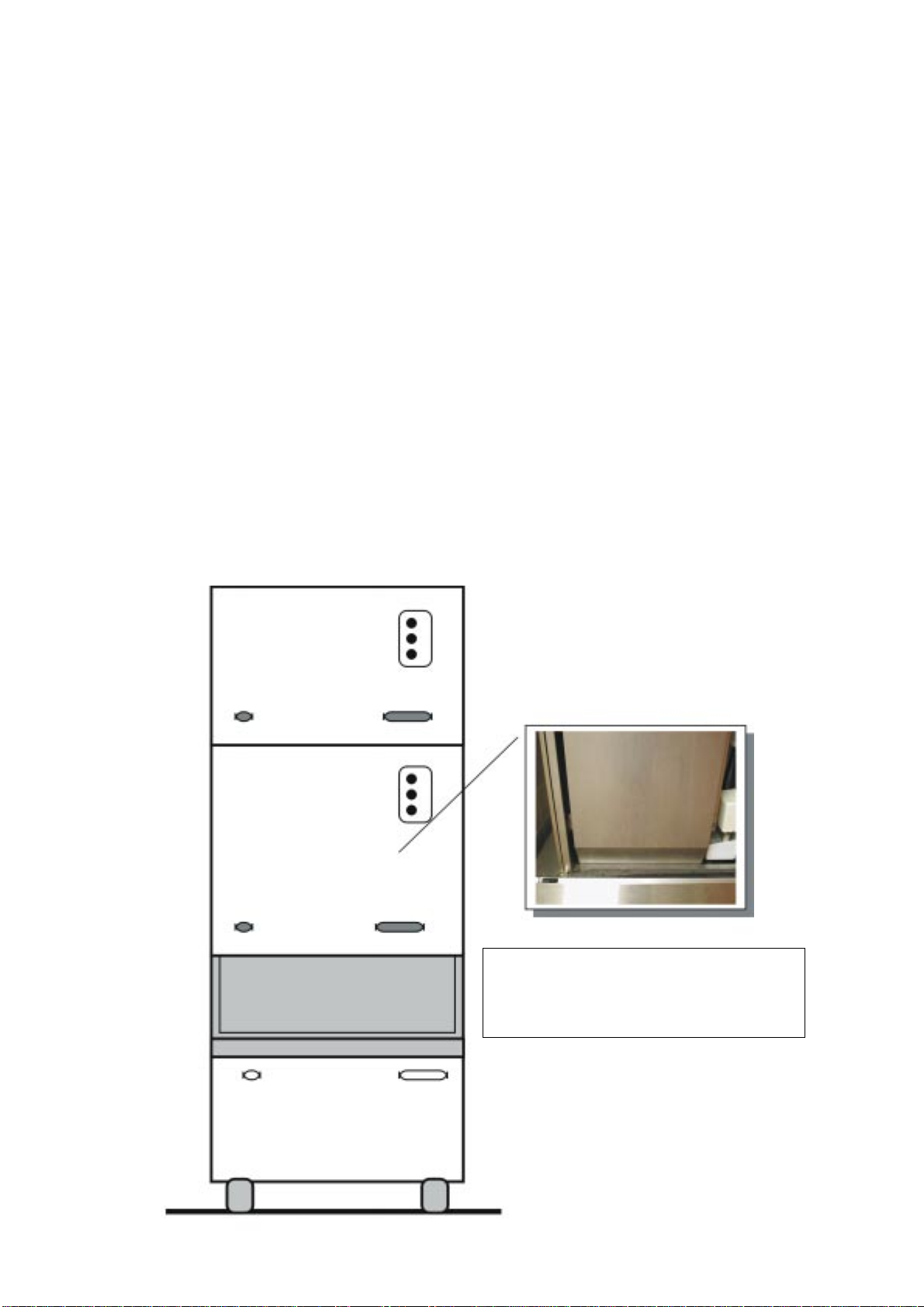
Remove front, top and sides panels.
Place the unit directly onto the bin, align it with
thebackofthebin.Locatethehardwarepackage,
take out two mounting screws, and use them to
secure the Icemaker to the two sides of the bin.
See illustration below.
Remove all shipping material as well as the
masking tapes from the ice deflector/evaporator
cover.
Remove first the ice deflector/evaporator cover
then the masking tape from the ice thickness
sensor.
SV 130 - AIR SEPARATOR
Installontherearrightsideofthemachinetheair
separator as per instruction provided with it.
STACKING INSTALLATION
To stack a second SV onto the present one, first
remove the top panel from the lower machine.
Add a bead of food grade silicone sealant to the
top edges of the lower units freezingcompart-
ment. Lift the top machine onto the bottom

Page 13
Page 13
When choosing the water supply for the SV
Cuber, consideration should be given to:
A. Length of run.
B. Water clarity and purity.
C. Adequate water supply pressures.
Sincewateristhemostimportantsingleingredient
in producing ice you cannot over emphasize the
three items listed above. Low water pressure,
below 1 bar may cause malfunction, of the
icemaker unit. Water containing excessive
minerals will tend to produce cloudy colored ice
cubes, plus scale build-up on parts in the water
system.
Heavilychlorinatedwatercanbecontrolledusing
charcoal or carbon filters.
DRAINS
AIR-COOLED MODELS: There is one 20 mm.
dia sump drain fitting at the back of the cabinet.
Insulations in high humidity areas is recom-
mended. The ideal drain receptacle would be a
trapped and vented floor drain.
WATER-COOLEDMODELS:Besidestheabove
drain, a separate condenser drain must be run.
Connect it to the - 3/4'’ gas - condenser drain
connection at the back of the cabinet.
STORAGE BIN: A separate gravity type drain
needs to be run, similar to the air-cooled sump
drain. Insulation of this drain line is recom-
mended.
FOR THE ELECTRICIAN
ELECTRICAL CONNECTIONS
The unit come equipped with an electrical cord
for power supply. The lead wires must be
connectedto an electricalplug that corresponds
to the local electrical codes and requirements or
to a separate two poles disconnect box with
opening to the contacts of about 3 millimeters.
The disconnect box shoulds be placed close to
the selected ice maker location to be easily and
prompt reached.
Undersized wiring or unproperly installed
electricalcircuitwillresult inmajorproblemsand
malfunctions.
Voltagevariationsshoudnotexceedtenpercent.
IMPORTANT-All plumbing and electrical
connections must be made by licensed
plumbers and electricians, this one must
followtheelectricalspecificationsprinted
on the ice maker nameplate.
NOTE: All SIMAG Cubers require a neutral
wireand asolid earth groundwire toprevent
possible severe Electrical Shock Injury to
individuals or extensive damage to
equipments.
machine, (the use of a mechanical lift is
recommended for this step). Align the two
machines cabinets, and using the 2 screw from
the top units, hardware package, fasten the two
units together at the side cabinets.
Then make use of the Stacking Kit KSC 12,
KSC21,KSC32orKSC50tobemountedasper
fitting instructions included in their package,
respectively on SV 130, SV 210, on SV 310 and
SV530locatedinthebottomforproperconveying,
of the ice cubes made by the top unit, into the
storage bin.
With food grade silicone perfectly seal the edge
between the freezing compartment of the upper
machine and of the bottom machine so to avoid
anypossibleleakofwaterthroughtheclearence
in between.
FOR THE PLUMBER
CONFORM TO ALL APPLICABLE CODES
WATER INLET
AIR-COOLED MODELS: The recommended
water supply is cold water, 3/8'’ O.D. copper
tubing,connecteda-3/4'’gas-malefittingatthe
back of the cabinet. Install a hand valve near the
machine to control the water supply.
1) Switch
2) Plug receptacle
3) Electrical plug
4) Water inlet
5) Shut-off valve
6) Water filter
7) Water outlet line
8) Bin water outlet line
9) Open vented water drain
10) Water outlet from the condenser:
water cooled version only.
Page 14
Page 14
FINAL CHECK LIST
1. Is the cabinet/bin level?
2. Is the cuber in a location where ambient
temperatures are a minimum of 10°C (50-de-
grees F.) all year around and to not exceed a
maximum of 40°C. (100°F.).
3. Is there at least a 15 cm. clearance behind
andaroundthecabinetforallconnectionsandfor
proper air circulation?
4. Have all electrical and piping connections
been made?
5. Has the electrical power supply wiring been
properly connected and the voltage tested and
checked against the nameplate rating? Has the
unit properly grounded.
6. Isthewatersupplylineshutoffvalveinstalled
and opened and has the inlet water supply
pressure been checked to insure a minimum of
1 bar without exceeding a maximum of 5 bar.
7. Have the compressor holddown bolts been
checked to be sure the compressor is snug on
the mounting pads.
8. Check all refrigerant lines and conduit lines
to gard against vibration and possible failure.
9. Has the cuber and the bin been wiped clean
with clean damp cloths?
10. Has the owner/user been given the User
Manual and instructed on how to operate the
icemaker and the importance of periodic
maintenance?
11. Has the owner/user been given the name
and telephone number of the Authorized
SCOTSMAN Distributor or Service Agency
serving him?
12. Has the Manufacturer’s Registration Card
been properly filled out?
Check for correct Model and Serial Numbers
fromnameplate, thenmailthecompletedcardto
the Manufactured.
TYPICAL STACKING INSTALLATION
KIT STACKING KCS 12: TO STACK 2 SV 130's
KIT STACKING KCS 21: TO STACK ON THE SV 210
KIT STACKING KCS 32: TO STACK ON THE SV 310
KIT STACKING KCS 50: TO STACK 2 SV 530's

Page 15
Page 15
START-UP
1. START-UP
1. If not yet done remove screws and pull the
Front Panel out.
2. Open the water supply line shut-off valve.
NOTE: Observe that the inlet water can be
seen flowing into the Sump Assembly.
Allow water to fill the Sump about three
minutes until the water is at level.
Thefloat shouldcausethe waterflow tostop
few mm. from reservoir overflow.
When the float has been risen from the water
filling the Sump Assy, the water has forced all
trapped air out of Water Pump and pump tube,
thus preventing the pumping of water filled with
air bubbles.
3. Put unit under power by moving power line
switch to ON position.
Immediately the fourth "LED" will glow and four-
five seconds later the third one too together with
the compressor.
Check operation of the freezing cycle:
a) Compressor is operating.
b) Fan motor (inaircooled version)controlled
bythecondensingtemperaturesensorlocatedin
contact with the condenser copper tube.
c) Water pump is operating as seen by water
moving through the tygon tube up to the water
distributor at the top of evaporator plate, where
waterisuniformlydistributedandcascadesdown
overtheegg-crateevaporatorbackintotheSump
for recirculation.
NOTE: The Water pump will start up after a
minutedelaytimecontrolledbythePCBoard
so to avoid any possibility to such air
(cavitation).
NOTE: Do not remove the evaporator
deflector cover as it will cause the switching
offofthemachineat"STORAGEBINFULL".
4. First freezing time will range between 19
and 22 minutes.
Longer time for temperature above 25°C and
shortertimerequiredwhentemperaturearebelow
25°C.
Average complete cycle time is about 22 min.
5. Makesureofcorrectoperationoffloatvalve
and water pump.
6. Check for any irregular noise source and if
any, eliminate it.
7. Observe first ice cube harvest and check
size of ice cubes; if an adjustment is required
threaddownoroutscrewN.1asshownonbelow
illustration.
This screw position determines the distance
between the sensor reeds and the egg-crate
evaporatorthuskeepingtheicecubeataproper
thickness.
NOTE: This type of machine produce an
"ICE PLATE" that breaks when falls down
intothestoragebin.Settingtheicethickness
sensor in order to have single ice cubes
may cause malfunction of the machine.
8. Observe second and third cube harvest.
Check if size and shape combination is correct.
Inareaswhereextremeproblemwaterconditions
exist, filtering or purifyng equipment is
recommended.
NOTE: If water used is too soft,
"demineralized" the ice thickness sensor
might not be able to sense the water on its
reeds, there by it will not switch the unit on
harvest cycle.
A safety system built in the P.C. Board
switches the unit on harvest cycle whenever
the freezing period gets longer then 40'.

Page 16
Page 16
seconds going through a 3' delay time (green
LED blinking).
10. Place again all cabinet panels and screws
previously removed.
11. Thoroughly explain to owner/user the
significant specifications of the ice maker start-
up, reset and operation, going through the
procedures in the operating instructions.
Answer all questions about the ice maker by the
ownerandinform the ownerhimseftof the name
and telephone number of the authorized service
agency serving him.
NOTE: To assure a correct operation of the
machine the water must have a minimum
electrical conductivity of 20 us.
9. Check operation of magnetic switch
controlling it by keeping open the bottom end of
plastic deflector for more than 30 seconds. The
machine must switch off at storage bin full.
Releasetheplasticdeflector.Themachineshould
restart in the freezing cycle mode within few

Page 17
Page 17
REFRIGERATION DURING FREEZE:
Thisicemachine employeseitherair orwateras
acondensingmedia,therefrigeration systemfor
either one is a follows:
At the hermetic compressor, Refrigerant is
compressed into a high temperature, high
pressure gas.
The gas moves through the discharge line into
thecondenser,airorwater-cooled.Ifair-cooled,
thedischarge pressurewill change with the heat
load and the ambient air temperature.
If water-cooled, the discharge pressure is
controlledbytheamountofwaterflowingthrough
the condenser - which is determined by the
water regulating valve.
After the gas is cooled in the condenser, giving
up much of its heat, the gas condenses into a
high pressure liquid. This liquid travels through
the liquid line to the metering device, a
thermostatic expansion valve on models
SV130-210-310andtwothermostaticexpansion
valves on model SV 530.
The thermostatic expansion valve meters how
much liquid refrigerant is to be allowed into the
evaporator section of the refrigeration system.
ThisisdeterminedbythetemperatureoftheTXV
sensing bulb, located on the suction line
manifold, at the outlet of the evaporator.
If the bulb senses a warm suction line, more
refrigerantisallowedintotheevaporator,(common
atthebeginningofthefreezecycle) andwhenthe
temperaturebeginstofall,lessrefrigerantisallowed
through.
This is why the suction side gauge pressure will
decline throughout the freeze cycle. At the
evaporator, the liquid refrigerant released from
high pressure, boils off in the low pressure
environment and absorbs heat, thus cooling the
evaporatorsurfaceandanything near it,suchas
water.
The low pressure refrigerant vapor then is
forced through the heat exchanger where any
excessliquidrefrigerantboils-off,allowingonly
refrigerant vapor to enter the compressor
suction tube, where it is recompressed into
high pressure, high temperature gas again
and the cycle repeats.
OPERATION
FREEZE CYCLE
REFRIGERATION SYSTEM SCHEMATIC

Page 18
Page 18
FREEZE CYCLE
the evaporator surface by gravity. As it flows
accrosstherefrigeratedevaporator,someofthe
waterwillbechilledenoughto change form,turn
to ice, and stay frozen onto the evaporator cells.
Most of the water returns to the reservoir, to be
sucked back into the pump, and repumped over
the evaporator.
WATER SYSTEM
A mechanical float valve is used to control the
level of the water into the reservoir/sump.
A pump, running continuously, after the first
minute of freezing cycle, forces the water to the
top of the evaporators, where it is distributed
through a water tube and then cascades down

Page 19
Page 19
HARVEST (DEFROST) CYCLE
REFRIGERATION SYSTEM SCHEMATIC
REFRIGERATION SYSTEM DURING
HARVEST
Therefrigerationsystemperformstheharvestof
ice by use of a hot gas bypass valve. When the
time comes to de-ice the evaporators, the hot
gas valve is energized, and the high temperatu-
re, high pressure gas bypasses the condenser,
and is allowed directly into the evaporator. The
highpressuregasiscooledbythecoldevaporator
soitcondensesintoaliquid,givingupitsheatas
it does so. This heat warms the evaporator and
theice frozenontotheevaporatorsurfacemelts,
releasing the frozen cubes. Ice then falls by
gravity into the storage bin.
The liquid refrigerant goes through the suction
line into the heat exchanger where it boils-off so
that only refrigerant vapor is drawn into the
suction tube of the compressor.
WATER SYSTEM
During the harvest cycle, the electric water
drain valve is energized thereby opening the
drain line.
All water remained in the reservoir at the end of
freezing cycle is pumped-out, to the waste,
through the water solenoid and drain line during
thefirst20seconds ofthedefrostcycleeliminating
any possible build-up and accumulation of
mineralsconcentrationandimpuritiesinthewater
reservoir.
Asthe pumpstops, the incoming water, passing
through the float valve, has still sufficient time,
before the beginning of the next start up of the
waterpump,toproperlyfillupthesump/reservoir,
sothattherewouldnotbeanycavitationproblem
when the water pump will resume its operation.
This grants a better ice formation inside the
cooling cells.
When the released ice cubes drop into the bin,
they open-up for a fraction of a seconds the
bottom end of plastic deflector.
Thisdeflectorswingingmotionisenoughtoreset
the contact of the magnetic switch which - via
electronic control board - deenergizes the water
drain valve allowing the unit to initiate a new
freezing cycle.

Page 20
Page 20
OnmodelSV530thereleaseoftheiceplatefrom
the second evaporator will cause the restart of
the machine in the freezing cycle.
NOTE: In case the P.C. Board does not
receive the pulse from the second magnetic
switch,after40 secondfromthefirst pulse,it
will switch the unit from defrost to freezing
cycle.
The harvest cycle lasts about 1.5÷2 minutes.
CONTROL SEQUENCE
At the start of the freezing cycle, the contacts of
the magnetic switch mechanically operated by
the actuator plate of the deflector cover are
closed, thereby - via electronic control board -
closing the circuit to the main contactor coil and
consequently to the compressor and fan motors
and to the water pump motors.
Then,astheicethicknessreachesthevaluethat
correspondstothefullcubesize,thefilmofwater
that constantly cascades over the slab of ice
formed on the evaporator, arrives to establish a
contact between the two fingers (energised at
lowvoltage) ofthe icesensor control,located on
thefront upper right side ofthe evaporator.If the
contactbetweenthetwofingersoftheicesensor
remains established - by the film of water - for
more than 10 seconds, a small relay of the
electronic board, get energized, controlling -
simultaneously both the hot gas valve and the
water drain valve.
NOTE: in case of failure of ice level sensor,
the P.C. Board turns - on automatically the
unit into the defrost cycle when the freezing
cycle reaches 40 minutes.
At this point, the unit initiates the defrost cycle.
The hot gas circulating into the evaporator
serpentine causes a slight melting of ice cubes
whichgetreleasedfromtheirmolds.Onceentirely
released the ice cubes drop simultaneously into
theicestoragebinbelow;bydoingsotheymove
apartfromtheevaporatorbottomendtheplastic
deflector. This plastic deflector has on its side a
magnetic switch that on account of the deflector
swingingmotion,causedbytheicewhiledropping
in the bin, opens and closes their contacts. This
will, in turn, disactivate the relay contacts that
controlsthehotgasandwater drain valvewhich
get deenergized allowing the unit to start a new
freezing cycle.
Whentheicebinisfullofice,thelastbatchofice
cubesreleasedfromtheevaporatoraccumulates
tokeep the bottomend of theplastic deflector in
openposition;withthemagneticswitchcontacts
open for longer than 30'’ the entire unit stops.
On model SV 530 in case one or both the ice
slabs, released from the evaporator, are
maintaininginopenpositiontheircorresponding
deflector for longer than 30 seconds, with the
consequent opening of the magnetic switch for
the same extension of time, the P.C. Board
cause the stopping of the unit operation. This
normally occures in the full ice storage bin
situation which are signalled by the
simoultaneousglowingofthecorrespondingLED.
The machine will restart when the ice deflector
willbebackinitsnormalverticalposition(bothfor
model SV 530) provided that 3' are elapsed from
unitstop.Ifnotthemachinewilldelayitsrestarttill
3'are elapsedwith theblinking ofthe greenLED.
This manual suits for next models
3
Table of contents
Other SIMAG Commercial Food Equipment manuals


Popular Commercial Food Equipment manuals by other brands


Diamond
Diamond AL1TB/H2-R2 Installation, Operating and Maintenance Instruction

Salva
Salva IVERPAN FC-18 User instructions

Allure
Allure Melanger JR6t Operator's manual

saro
saro FKT 935 operating instructions

Hussmann
Hussmann Rear Roll-in Dairy Installation & operation manual

Cornelius
Cornelius IDC PRO 255 Service manual

Moduline
Moduline HSH E Series Service manual

MINERVA OMEGA
MINERVA OMEGA DERBY 270 operating instructions

Diamond
Diamond OPTIMA 700 Installation, use and maintenance instructions

Diamond
Diamond G9/PLCA4 operating instructions

Cuppone
Cuppone BERNINI BRN 280 Installation

Arneg
Arneg Atlanta Direction for Installation and Use