SIMAG SCN 35 User manual

SCN 35
SCN 45
SCN 75
SCN 125
SCN 215
Automatic cubers
Automatic Kegeleisbereiter
090091.05 - REV. 04/2015

TABLE OF CONTENTS PAGE INHALTSVERZEICHNIS SEITE
GENERAL INFORMATION AND INSTALLATION 1 ALLGEMEINES UND INSTALLATION 14
Introduction 1 Einführung 14
Unpacking and inspection 1 Auspacken und Inspektion 14
Location and levelling 1 Maschinenplatz und lotgerechte Austellung 14
Electrical connection 1 Elektrische Anschlüße 15
Water supply and drain connection 2 Wasserversorgung und Abflußleitungen 15
Final check list 3 Schlußkontrollen 15
Installation practice 3 Installation 16
OPERATING INSTRUCTION 4 BETRIEBSANLEITUNG 17
Starp up 4 Inbetriebnahme 17
Operational checks 4 Ueberprüfung im Betrieb 17
OPERATING PRINCIPLES 6 FUNKTIONSSYSTEME 19
Freezing Cycle 6 Gefrierprozess 19
Harvest Cycle 6 Abtauprozess 19
Control sequence 7 Steuersequenzen 20
Electrical sequence 7 Sequenz Elektrische Bestandteile 20
Components description 8 Komponentenbeschrieb 21
Service diagnosis 10 Fonktionsfehler 23
MAINTENANCE AND CLEANING INSTRUCTIONS 12 WARTUNG UND REINIGUNGSANLEITUNG 25
General 12 Woraussetzung 25
Icemaker 12 Reinigung des Eisbereiters 25
Clean - Replace of air condenser filter 12 Reinigung - Austausch des Luftkondensatorfilters 25
Cleaning instructions of water system 12 Wartungs und Reinigungsanleitungen 26
A

B
Ice making capacity - Eisproduktionskapazität
SCN 35
34
33
32
31
30
29
28
27
26
25
24
23
Kg.
25 10 °C20 15
°C
10
20
30
35
AIR COOLED MODELS - LUFTKÜHLUNG
WATER TEMPERATURE - WASSERTEMPERATUR
AMBIENT TEMPERATURE - RAUMTEMPERATUR
ICE PRODUCED PER 24 HRS. - EISWÜRFEL PRODUKTION IN 24 STD.
WATER COOLED MODELS - WASSERKÜHLUNG
Kg.
25 10 °C20 15
°C
10
20
30
35
WATER TEMPERATURE - WASSERTEMPERATUR
AMBIENT TEMPERATURE - RAUMTEMPERATUR
ICE PRODUCED PER 24 HRS. - EISWÜRFEL PRODUKTION IN 24 STD.
37
36
35
34
33
32
31
30
29
28
27
26
25
24
23
SCN 45
43
42
41
40
39
38
37
36
35
34
33
Kg.
25 10 °C20 15
°C
10
20
30
35
AIR COOLED MODELS - LUFTKÜHLUNG
WATER TEMPERATURE - WASSERTEMPERATUR
AMBIENT TEMPERATURE - RAUMTEMPERATUR
ICE PRODUCED PER 24 HRS. - EISWÜRFEL PRODUKTION IN 24 STD.
WATER COOLED MODELS - WASSERKÜHLUNG
47
46
45
44
43
42
41
40
39
38
37
Kg.
25 10 °C20 15
WATER TEMPERATURE - WASSERTEMPERATUR
AMBIENT TEMPERATURE - RAUMTEMPERATUR
ICE PRODUCED PER 24 HRS. - EISWÜRFEL PRODUKTION IN 24 STD.
°C
10
20
30
35
SCN 75
65
64
63
62
61
60
59
58
57
56
55
54
53
Kg.
25 10 °C20 15
°C
10
20
30
35
AIR COOLED MODELS - LUFTKÜHLUNG
WATER TEMPERATURE - WASSERTEMPERATUR
AMBIENT TEMPERATURE - RAUMTEMPERATUR
ICE PRODUCED PER 24 HRS. - EISWÜRFEL PRODUKTION IN 24 STD.
WATER COOLED MODELS - WASSERKÜHLUNG
68
67
66
65
64
63
62
61
60
Kg.
25 10 °C20 15
°C
10
20
30
35
WATER TEMPERATURE - WASSERTEMPERATUR
AMBIENT TEMPERATURE - RAUMTEMPERATUR
ICE PRODUCED PER 24 HRS. - EISWÜRFEL PRODUKTION IN 24 STD.

B/bis
Ice making capacity - Eisproduktionskapazität
SCN 125
136
132
128
124
120
116
112
108
104
100
96
92
88
84
80
Kg.
30 10 °C20 15
°C
10
20
30
35
AIR COOLED MODELS - LUFTKÜHLUNG
WATER TEMPERATURE - WASSERTEMPERATUR
AMBIENT TEMPERATURE - RAUMTEMPERATUR
ICE PRODUCED PER 24 HRS. - EISWÜRFEL PRODUKTION IN 24 STD.
25
SCN 215
162
158
154
150
146
142
138
134
130
126
122
118
114
110
106
102
98
94
90
Kg.
30 10 °C20 15
°C
10
20
30
35
AIR COOLED MODELS - LUFTKÜHLUNG
WATER TEMPERATURE - WASSERTEMPERATUR
AMBIENT TEMPERATURE - RAUMTEMPERATUR
ICE PRODUCED PER 24 HRS. - EISWÜRFEL PRODUKTION IN 24 STD.
25

C
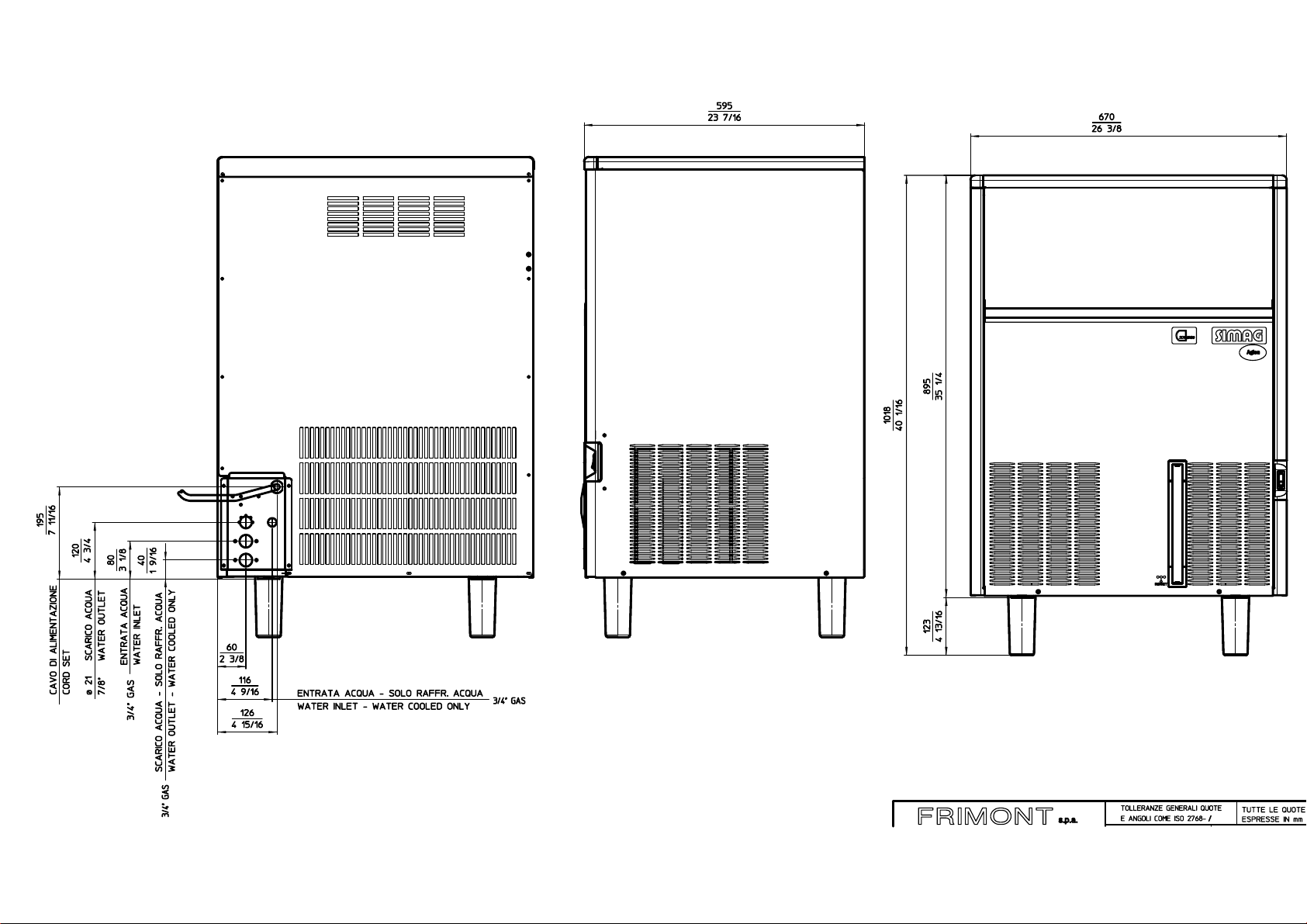
SDN 25 (mm) SDN 30 (mm) SDN 35 (mm) SCN 35 (mm) SCN 45 (mm)
A334 377 377 485 485
B454 552 552 572 572
C597 637 637 721 816
➊ CORD SET -
ELEK. KABEL
➋ Ø 20 WATER OUTLET -
WASSERABFLUSS
➌ G3/4" WATER INLET -
WASSEREINLAUF
SDN 25 - 30
SCN 35 - 45
123
1
2
3
BA
C
BA
C
SCN 75

SCN 125

SCN 215

E TECHNICAL SPECIFICATIONS - TECHNISCHE ANGABEN
SCN35 SCN35W SCN45 SCN45W SCN75 SCN75W SCN125 SCN125W SCN215 SCN215W
Electric voltage 230/50/1 230/50/1 230/50/1 230/50/1 230/50/1
Normale Netzspannung -10÷+10% -10÷+10% -10÷+10% -10÷+10% -10÷+10%
Condensation Air-Water Air-Water Air-Water Air-Water Air-Water
Kùhlung Luft-Wasser Luft-Wasser Luft-Wasser Luft-Wasser Luft-Wasser
Bin Capacity (kg) 17 20 30 50 68
Speiker Kapazitat (kg) 17 20 30 50 68
Net weight (kg) 45 48 61 94 131
Netto Gewicht (kg) 45 48 61 94 131
Compressor power HP 1/4 3/8 1/2 1 1.5
Kompressorleistung PS 1/4 3/8 1/2 1 1.5
Running amps 2.2 3.2 3.8 5.3 5.5
Ampere 2.2 3.2 3.8 5.3 5.5
Start amps 11 17 20 29 32
Start ampere 11 17 20 29 32
Power (Watt) 380 530 650 1200 2000
Leistung (Watts) 380 530 650 1200 2000
Power cons .in 24 hrs (Kwh) ) 7.5 10.5 13 24 35
Stromverbrauch in 24 hrs (Kwh) 7.5 10.5 13 24 35
Wire size (mm') 3 x1 3x1 3x1 3 x 1,5 3 x 1,5
Kabelanzahl (mm') 3 x1 3x1 3x1 3 x 1,5 3 x 1,5
Refrig. Charge R134A (gr) 280-240 300-270 450-300
Kuhlmittel full. R134A (gr) 280-240 300-270 450-300
Refrig. Charge R404A (gr) 630-500 660-500
Kuhlmittel full. R404A (gr) 630-500 660-500
Refrigerant metering device CapiIlary tube CapiIlary tube CapiIlary tube CapiIlary tube CapiIlary tube
Kaltemittel expansionssystem Kapillarrohr Kapillarrohr Kapillarrohr Kapillarrohr Kapillarrohr
OPERATING PRESSURES – BETRIEBSDRUCKE
Discharge pressure - Hochdruckbereich
SCN 35 SCN 45 SCN 75 SCN 125 SCN 215
Air Cooled (21°C)
8,5÷10 bar 8,5÷10 bar 8,5÷9,5 bar 15÷19,5 bar 16÷20 bar
Luftgekuhlt (21°C
Water Cooled
8,5÷10 bar 8,5÷10 bar 9,5 bar 17 bar 17 bar
Wassergekuhlt
Suction Pressure – Niederdruck
Start/End of freezing cycle – Beginn /Ende derGefrierfase
SCN 35 SCN 45 SCN 75 SCN 125 SCN 215
0,8÷0,1 bar 0,8÷0,1 bar 0,8÷0,1 bar 3,6÷1,5 bar 2,4÷1,3 bar

WIRING DIAGRAM - SCHALTUNGSSCHEMA
230/50/1
AIR & WATER COOLED - LUFT UND WASSERGEKÜHLT
SCN 35-45-75

WIRING DIAGRAM - SCHALTUNGSSCHEMA
230/50/1
AIR & WATER COOLED - LUFT UND WASSERGEKÜHLT
SCN 125 – SCN 215

GENERAL INFORMATION
AND INSTALLATION
A. INTRODUCTION
This manual provides the specifications and the
step-by-step procedures for the installation, start-
up and operation, maintenance and cleaning for
the SIMAG SCN Series Icemakers.
The SIMAG SCN cubers are quality designed,
engineered and manufactured.
Their ice making systems are thoroughly tested
providing the utmost in flexibility to fit the needs
of a particular user.
NOTE. To retain the safety and performance
built into this icemaker, it is important that
installation and maintenance be conducted
in the manner outlined in this manual.
B. UNPACKING AND INSPECTION
1. Call your authorized SIMAG Distributor or
Dealer for proper installation.
2. Visually inspect the exterior of the packing
and skid. Any severe damage noted should be
reported to the delivering carrier and a concealed
damage claim form filled in subjet to inspection of
the contents with the carrier’s representative
present.
3. a) Cut and remove the plastic strip securing
the carton box to the skid.
b) Remove the packing nails securing the
carton box to the skid.
c) Cut open the top of the carton and remove
the polystyre protection sheet.
d) Pull out the polystyre posts from the
corners and then remove the carton.
4. Remove the front and the rear panels of the
unit and inspect for any concealed damage.
Notify carrier of your claim for the concealed
damage as stated in step 2 above.
5. Remove all internal support packing and
masking tape.
6. Check that refrigerant lines do not rub
against or touch other lines or surfaces, and that
the fan blades move freely.
7. Check that the compressor fits snugly onto
all its mounting pads.
8. See data plate on the rear side of the unit
and check that local main voltage corresponds
with the voltage specified on it.
CAUTION. Incorrect voltage supplied to
the icemaker will void your parts
replacement program.
9. Remove the manufacturer’s registration
card from the inside of the User Manual and fill-
in all parts including: Model and Serial Number
taken from the data plate.
Forward the completed self-addressed
registration card to SIMAG factory.
C. LOCATION AND LEVELLING
WARNING. This Ice Maker is designed for
indoor installation only. Extended periods
of operation at temperature exceeding
the following limitations will constitute
misuse under the terms of the SIMAG
Manufacturer’s Limited Warranty resulting
in LOSS of warranty coverage.
1. Position the machine bin in the selected
permanent location and tighten the four legs
(SCN 35 - 45 - SCN 75 - 125 - 215).
Criteria for selection of location include:
a) Minimum room temperature 10°C (50°F)
and maximum room temperature 40°C (100°F).
b) Water inlet temperatures: minimum 5°C
(40°F) and maximum 40°C (100°F).
c) Well ventilated location for air cooled
models (clean the air cooled condenser at
frequent intervals).
d) Service access: adequate space must be
left for all service connections through the rear of
the ice maker. A minimum clearance of 15 cm
(6") must be left at the sides of the unit for routing
cooling air drawn into and exhausted out of the
compartment to maintain proper condensing
operation of air cooled models.
NOTE. With the unit in “built-in” conditions,
the ice production is gradually reduced in
respect to the levels shown in the graph, up
to a maximum of 10% at room temperatures
higher than 32
°
C.
The daily ice-making capacity is directly
related to the condenser air inlet temperatu-
re, water temperature and age of the machine.
To keep your SIMAG CUBER at peak perfor-
mance levels, periodic maintenance checks
must be carried out as indicated on this
manual.
2. Level the Icemaker in both the left to right
and front to rear directions by means of the
adjustable legs.
D. ELECTRICAL CONNECTIONS
See data plate for current requirements to
determine wire size to be used for electrical
connections. All SIMAG icemakers require a
solid earth wire.
All SIMAG ice machines are supplied from the
factory completely pre-wired and require only
electrical power connections to the wire cord
provided at the rear of the unit.
Page 1

Make sure that the ice machine is connected to
its own circuit and individually fused (see data
plate for fuse size).
The maximum allowable voltage variation should
not exceed -10% and +10% of the data plate
rating. Low voltage can cause faulty functioning
and may be responsible for serious damage to
the overload switch and motor windings.
NOTE. All external wiring should conform to
national, state and local standards and
regulations.
Check voltage on the line and the ice maker’s
data plate before connecting the unit.
E. WATER SUPPLY AND DRAIN
CONNECTIONS
GENERAL
When choosing the water supply for the cuber
consideration should be given to:
a) Length of run
b) Water clarity and purity
c) Adequate water supply pressure
Since water is the most important single ingredient
in producing ice you cannot emphasize too much
the three items listed above.
Low water pressure, below 1 bar may cause
malfunction of the ice maker unit.
Water containing excessive minerals will tend to
produce cloudy colored ice cubes, plus scale
build-up on the interior parts of the water system.
WATER SUPPLY
Connect the 3/4" GAS male of the water inlet
fitting, using the food grade flexible tubing supplied
with the machine, to the cold water supply line
with regular plumbing fitting and a shut-off valve
installed in an accessible position between the
water supply line and the unit.
If water contains a high level of impurities, it is
advisable to consider the installation of an
appropriate water filter or conditioner.
WATER SUPPLY - WATER COOLED MODELS
(SCN 75-125-215)
The water cooled versions of SIMAG Ice Makers
require two separate inlet water supplies, one for
the water making the ice and the other for the
water cooled condenser.
Connect the 3/4" GAS male fitting of the water
inlet, using the flexible tubing supplied with the
unit, to the cold water supply line with regular
plumbing fitting and a shut-off valve installed in
an accessible position between the water supply
line and the unit.
WATER DRAIN
Connect the drain fitting with a plastic tube to an
open trapped and vented drain. When the drain
is a long run, allow 3 cm pitch per meter (1/4"
pitch per foot).
On water cooled versions, the water drain line
from the condenser is internally connected with
the drain fitting of the unit.
It is strongly recommended therefore to install a
vertical open vent on unit drain line high point to
ensure good draining and to direct the drain line
to a trapped and vented floor drain receptacle.
NOTE. The water supply and the water drain
must be installed to conform with the local
code. In some case a licensed plumber and/
or a plumbing permit is required.
Page 2

G. INSTALLATION PRACTICE
1. Hand shut-off valve
2. Water filter
3. Water supply line (flexible hose)
4. 3/4" GAS male fitting
5. Vented drain
6. Open trapped vented drain
7. Drain fitting
8. Main switch
9. Power line
7. Have the bolts holding the compressor down
been checked to ensure that the compressor is
snugly fitted onto the mounting pads?
8. Check all refrigerant lines and conduit lines
to guard against vibrations and possible failure.
9. Have the bin liner and cabinet been wiped
clean?
10. Has the owner/user been given the User
Manual and been instructed on the importance of
periodic maintenance checks?
11. Has the Manufacturer’s registration card been
filled in properly? Check for correct model and
serial number against the serial plate and mail
the registration card to the factory.
12. Has the owner been given the name and the
phone number of the authorized SIMAG Service
Agency serving him?
F. FINAL CHECK LIST
1. Is the unit in a room where ambient
temperatures are within a minimum of 10 °C
(50°F) even in winter months?
2. Is there at least a 15 cm (6") clearance
around the unit for proper air circulation?
3. Is the unit level? (IMPORTANT)
4. Have all the electrical and plumbing
connections been made, and is the water supply
shut-off valve open?
5. Has the voltage been tested and checked
against the data plate rating?
6.
Has the water supply pressure been checked
to ensure a water pressure of at least 1 bar
(14 psi)? Open the shut-off valve and verify the
absence of water losses from the connections.
WARNING. This icemaker is not designed for outdoor installation and will not function in
ambient temperatures below 10°C (50°F) or above 40°C (100°F).
This icemaker will malfunction with water temperatures below 5 °C (40°F) or above 40 °C
(100°F).
Page 3

OPERATING
INSTRUCTIONS
START UP
After having correctly installed the ice maker and
completed the plumbing and electrical
connections, perform the following “Start-up”
procedure.
A. Put the icemaker in operation by moving the
unit master switch, located on the cabinet front,
to the ON position.
NOTE. The icemaker control is factory set
with the timer microswitches actuators
dropped off into the initial point of the cam
slot. This setting position allows a proper
water filling.
The unit starts operating in the “defrost cycle”
with the following components being activated:
THE WATER INLET SOLENOID VALVE
THE HOT GAS SOLENOID VALVE
THE CONTACTOR COIL (SCN 75-125-215)
THE FAN MOTOR (only SCN 35) air cooled
THE COMPRESSOR
THE TIMER MOTOR
B. During the water filling operation, check to
see that the incoming water dribblers, through
the evaporator platen dribbler holes, down into
the sump reservoir to fill it up and also that the
incoming surplus of water flows out through the
overflow pipe into the drain line.
NOTE. If, in the defrost cycle length, the
machine sump reservoir does not get filled
with water up to the rim of the overflow pipe,
remove the front panel and rotate the shaft of
the timer so to cause the dropping of the two
microswitches actuators into the beginning
of the cam slot and check for:
1. The water pressure of the water supply
line, it must be at least 1 bar (14 psig)
Minimum (Max 5 bar-70 psig).
2. The filtering device installed in the water
line that may reduce the water pressure
below the Minimum value of 1 bar (14 psig).
3. Any clogging situation in the water circuit
like the inlet water strainer and/or the flow
control.
OPERATIONAL CHECKS
C. At completion of the water filling phase the
unit initiate automatically the first freezing cycle
with the start up of (Fig.1):
COMPRESSOR
CONTACTOR COIL (SCN 75-125-215)
WATER PUMP
FAN MOTOR (in air cooled version)
D. Check to see through the ice discharge
opening that the spray system is correctly seated
and that the water jets uniformely reach the
interior of the inverted mold cups or the exterior
of the evaporator tips; also make sure that the
plastic curtain is hanging freely and there is not
excessive water spilling through it.
E. The ice making process takes place thereby,
with the water sprayed into the molds or onto the
tips that gets gradually refrigerated by the heat
exchange with the refrigerant flowing into the
evaporator serpentine.
During the first portion of the freezing cycle, the
timer assy is standing-by with its microswitches
actuators resting on the raised cam profile
(position that correspond to the end of the defrost
cycle).
F. Then, as the cube size control cut-in point is
reached by the evaporator temperature the control
of the cycle is passed to the timer assy. Whose
raised cam slowly rotates to continue the freezing
cycle (2nd phase) up to its completition.
The components in operation during this 2nd
phase of the cycle are:
COMPRESSOR
CONTACTOR COIL (SCN 75-125-215)
WATER PUMP
FAN MOTOR (in air cooled version)
TIMER MOTOR
G. After about 18 ÷20 minutes from the
beginning of the freezing cycle, in an hypothetic
ambient temperature of 21°C, the defrost cycle
takes place with the hot gas and the water inlet
valves being simoultaneously activated.
The electrical components in operation are:
COMPRESSOR
CONTACTOR COIL (SCN 75-125-215)
WATER INLET SOLENOID VALVE
HOT GAS VALVE
TIMER MOTOR
FAN MOTOR (only SCN 35) air cooled
H. Check, during the defrost cycle, that the
incoming water flows correctly into the sump
reservoir in order to refill it and that the surplus
overflows through the overflow drain tube.
I. Check the texture of ice cubes just released.
They have to be of the right size with a thickness
of about 7÷8 mm.
If the ice cubes have not the correct size, wait for
a second harvest before attempting any
adjustment by setting the cube size control.
Page 4

Page 5
By rotating the control setting screw clockwise
the ice cube thickness can be increased; on the
contrary the thickness can be reduced by turning
the setting screw counterclockwise.
If the ice cubes are shallow and cloudy, it is
possible that the ice maker runs short of water
during the freezing cycle second phase or, the
quality of the supplied water requires the use of
an appropriate water filter or conditioner.
J. With the icemaker in the harvest cycle, hold
ice against the bin thermostat control bulb to
test its shut off. This should cause the ice
maker to shut OFF after 30 seconds, 1 minute
at the most, namely when the control bulb
temperature drops to reach +1°C.
NOTE. In case this test is performed during
the freezing cycle, the unit will shut OFF
only at the end of the freezing cycle.
Within minutes after the ice is removed
from the sensing bulb, the bulb will warm
up to reach + 4°C and consequently will
cause the icemaker to restart from the
harvest (defrost) cycle.
K. Instruct the owner/user on the general
operation of the ice machine and about
the cleaning and care it requires.

PRINCIPLE OF OPERATION
In the SIMAG cube ice makers the water used to
make the ice is kept constantly in circulation by
an electric water pump which primes it to the
spray system nozzles from where it is diverted
into the molds of the evaporator.
A small quantity of the sprayed water freezes into
ice; the rest of it cascades by gravity into the
sump assembly below for recirculation.
FREEZING CYCLE
The hot gas refrigerant discharged out from the
compressor reaches the condenser where, being
cooled down, condenses into liquid. Flowing into
the liquid line it passes through the drier filter,
then it goes all the way through the capillary tube
where, due to the heat exchanging action, it
looses some of its heat content so that its pressure
and temperature are lowered as well.
Next the refrigerant enters into the evaporator
serpentine (which has a larger I.D. then the
capillary) and starts to boil off; this reaction is
emphasized by the heat transferred by the
sprayed water.
The refrigerant then increases in volume and
changes entirely into vapor.
The vapor refrigerant then passes through the
suction accumulator (used to prevent that any
small amount of liquid refrigerant may reach the
compressor) and through the suction line. In both
the accumulator and the suction line it exchanges
heat with the refrigerant flowing into the capillary
tube (warmer), before to be sucked in the
compressor and to be recirculated as hot
compressed refrigerant gas.
The freezing cycle is controlled by the evaporator
thermostat (which has its bulb in contact with the
evaporator serpentine) that determines the length
of its first portion of the cycle.
When the temperature of the evaporator
thermostat bulb drops to a pre-set value, the
evaporator thermostat changes its contacts (from
3-4 to 3-2) suppling power to the finishing timer
that takes the control of the second timed portion
of the freezing cycle up to its completion.
The length of this second timed portion of the
freezing cycle is pre-fixed.
.
The electrical components in operation during
the freezing cycle are:
COMPRESSOR
CONTACTOR COIL (SCN 75-125-215)
FAN MOTOR (in air cooled version)
WATER PUMP
and during the second phase of freezing cycle
(Time mode) they are joined by the
TIMER
On the SCN 45, SCN75, SCN125 and SCN215 air
cooled the refrigerant head pressure, in the course
of the freezing cycle, ranges between 8÷10 bars
SCN 45, 8÷9,5 bars SCN75 and 15,5÷20 bars
SCN 125-215 being controlled by the hi-pressure
control.
When the discharge pressure rises up to a pre
set value, the pressure control closes its electrical
contacts suppling power to the FAN MOTOR.
As soon as the discharged refrigerant pressure
drops, the pressure control opens its contacts to
temporarely de-energize the fan motor. On others
air cooled models (SCN 35) the fan motor is
constantly activated and retain the head pressure
between 8÷10 bars (110÷140 psig).
On the models from S CN 35÷45 water cooled
version the same hi-pressure control is used to
intermittently energize a water solenoid valve
located on the water supply line to the condenser.
On the other models SCN75-125-215, in water
cooled version, the discharge pressure is kept
constant by the water regulating valve that meters
the water flow to the condenser.
NOTE. In case of shortage/insufficient cooling
water or air condenser dirty, the operation of
the safety device by hand reset will stop the
machine as soon as the temperature reach
70/75
°
C (160/170
°
F) or the corresponding
pressure. After eliminated the cause of the
stop, put the machine in operation by
pushing the reset button of the safety
thermostat or pressure switch across the
holes in the down/right side of the front panel
or removing it.
At the start of the freezing cycle the refrigerant
suction or lo-pressure lowers rapidly to 0,8 bars
(11 psig) SCN 35÷SCN75, 3,6 bars (50 psig)
SCN125and 2,4 bars (34 psig) SCN 215 then it
declines gradually - in relation with the growing of
the ice thickness - to reach, at the end of the
cycle, approx. 0,1 bars (1,4 psig) SCN 35÷SCN75,
1,5 bars (21 psig) SCN 125, and 1,3 bars (18
psig) SCN 215 with the cubes fully formed in the
cup molds.
The total length of the freezing cycle ranges from
18 to 20 minutes.
DEFROST OR HARVEST CYCLE
As the electric timer has carried the system
throughout the second phase of freezing cycle,
the defrost cycle starts.
NOTE. The length of the defrost cycle is pre-
determined by the setting of timer
o
In case it is possible to modify the defrost
cycle length through its trimer
ATTENTION. The defrost period is the
most critical for the icemaker main
components expecially the compressor.
To avoid to abuse of them it is strongly
recommended to limit the harvest cycle
extension to 4 minutes at the most.
The electrical components in operation during
this phase are:
COMPRESSOR
Page 6

CONTACTOR COIL (SCN 75-125-215)
FAN MOTOR (only SCN 35) air cooled
WATER INLET SOLENOID VALVE
HOT GAS SOLENOID VALVE
TIMER MOTOR
The incoming water, passing through the water
inlet valve and in its incorporated flow control
(outlet), runs over the evaporator platen and then
flows by gravity through the dribbler holes down
into the sump/reservoir.
The water filling the sump/reservoir forces part of
the left-over water from the previous batch to run
out to the waste through the overflow pipe. This
overflow limits the level of the sump water which
will be used to produce the next batch of ice
cubes.
Meanwhile, the refrigerant as hot gas, discharged
from the compressor, flows through the hot gas
valve directly into the evaporator serpentine by-
passing the condenser.
The hot gas circulating into the serpentine of the
evaporator warms up the copper molds or the
tips causing the defrost of the ice cubes. The ice
cubes, released from the molds, drop by gravity
onto a slanted grid chute, then through a curtained
opening they fall into the storage bin.
At the end of the defrost cycle, both the hot gas
and the water inlet valves close and the machine
starts again a new freezing cycle.
OPERATION - CONTROL SEQUENCE
At the start of freezing cycle, the evaporator
thermostat controls the length of the first part of
the freezing cycle. As its bulb senses a
predetermined temperature, it closes its contacts
to supply power to the timer motor which, in turn,
takes over the control of the freezing cycle.
This second part of the cycle has a pre-fixed time
duration of 12 minutes.
.
NOTE. The evaporator thermostat is factory
set to the number 4 of its setting dial.
In case it is required the setting of the
evaporator thermostat can be made by turning
its adjusting screw located on front side.
With a clockwise rotation of the setting screw
the thermostat cut IN temperature will be
lowered (longer freezing cycle - thicker ice
cube) while, with a counterclockwise rotation
of the screw, the Cut IN temperature rises
(shorter freezing cycle - thiner ice cube).
Once completed the freezing cycle 2nd phase
the system switches automatically into the defrost
cycle which has a pre-fixed length as well.
At completion of the defrost period the unit starts
again a new freezing cycle.
OPERATION - ELECTRICAL SEQUENCE
The following charts illustrate which switches
and which components are ON or OFF during a
particular phase of the icemaking cycle.
Refer to the wiring diagram for a reference.
NOTE. The wiring diagram shows the unit as
it is in the Evaporator Thermostat mode of the
Freezing Cycle.
BEGINNING FREEZE
Electrical components (Loads) ....... ON OFF
Compressor........................................ •
Fan motor ........................................... •
Hot gas valve ..................................... •
Water inlet valve................................. •
Water pump........................................ •
Contactor coil ..................................... •
Timer motor ........................................ •
Electric Controls .............................. ON OFF
Conctats 3-4 evaporator thermostat .. •
Conctats 3-2 evaporator thermostat .. •
Bin thermostat .................................... •
Conctats timer •
Conctats timer •
Pressure control
(SCN35÷45W) (SCN45÷SC215A)
•
TIMED FREEZE
Electrical components (Loads) ....... ON OFF
Compressor........................................ •
Fan motor ........................................... ••
Hot gas valve ..................................... •
Water inlet valve................................. •
Water pump........................................ •
Contactor coil ..................................... •
Timer motor ........................................ •
Electric Controls .............................. ON OFF
Conctats 3-4 evaporator thermostat .. •
Conctats 3-2 evaporator thermostat .. •
Bin thermostat .................................... •
Conctats timer •
Conctats timer •
Pressure control
(SCN35÷45W) (SCN45÷SC215A) •
•
I° PORTION HARVEST CYCLE
Electrical components (Loads) ....... ON OFF
Compressor........................................ •
Fan motor (SCN 35 ON) .............. •
Hot gas valve ..................................... •
Water inlet valve................................. •
Water pump........................................ •
Contactor coil ..................................... •
Timer motor ........................................ •
Electric Controls .............................. ON OFF
Conctats 3-4 evaporator thermostat .. •
Conctats 3-2 evaporator thermostat .. •
Bin thermostat .................................... •
Conctats timer •
Conctats timer •
Pressure control
(SCN35÷45W) (SCN45÷SC215A) •
Page 7

II° PORTION HARVEST CYCLE
Electrical components (Loads) ....... ON OFF
Compressor........................................ •
Fan motor (SCN 35 ON) ............... •
Hot gas valve ..................................... •
Water inlet valve................................. •
Water pump........................................ •
Contactor coil ..................................... •
Timer motor ........................................ •
Electric Controls .............................. ON OFF
Conctats 3-4 evaporator thermostat .. •
Conctats 3-2 evaporator thermostat .. •
Bin thermostat .................................... •
Conctats timer •
Conctats timer •
Pressure control
(SCN35÷45W) (SCN45÷SC215A) •
•
OPERATING CHARACTERISTICS
On air cooled models during the freezing cycle
the discharge pressure is kept between 8 ÷10
bars (110÷140 psig) SCN35÷SCN75, 15,5÷20 bars
(215÷280 psig) SCN125-215.
At the same time the suction pressure will
gradually decline, reaching its lowest point just
before harvest. Compressor amps experience a
similar drop.
COMPONENTS DESCRIPTION
A. MASTER SWITCH
Fitted on the front side of the unit cabinet the
master switch has to be used to start-up and to
stop the ice maker operation.
In connection with it there is the green monitor
light.
B. EVAPORATOR THERMOSTAT
The evaporator thermostat with its sensing bulb
intimately in contact with the refrigerant outlet
tube from the evaporator, senses the evaporating
refrigerant temperature (which declines in the
course of the freezing cycle) and when this one
reaches the pre-set value, it switches its contacts
from 3-4 to 3-2 to activate the finishing cycle (2nd
phase) which has a pre-set extension determined
by the large diameter lobe of the timer cam.
C. BIN THERMOSTAT
The bin thermostat, which has its sensing bulb
downward into the storage bin, shuts-OFF
automatically the icemaker when the ice storage
bin is filled and ice contacts its bulb. Being it
connected in series with the front microswitch of
the timer, it causes the unit shut-off only at the
end of the freezing cycle, when the ice cubes are
completed.
After ice is removed from the bin and its bulb
warm-up it allows the unit to restart from the
beginning of the harvest cycle which, in the
circumstance, is more likely a water filling cycle.
D. TIMER
Equipped with two DIP switch and a Potentiometer.
it is located inside the control box.
.
The function of the timer begins when activated
by the cube size control (evap. thermostat).
The large diameter lobe of its cam determines
the 2nd freezing cycle portion length, while the
cam small diameter lobe, determines the time
cycle for the harvest sequence
Potentiometer used to adjust the defrost
time from 60" min to 180" max.
WARNING. Never set the defrost time for
longer than 4 minutes as this will
jeopardize the compressor motor
windings.
It goes without saying that an extension of the
defrost period will directly reduce the timed portion
of the freezing cycle and viceversa.
Consequently any variation made at the timer
requires a compensation adjustment,
very fine and very accurate, of the evaporator
thermostat.
E. COMPRESSOR DIP SWITCH
The compressor DIP switch is located on the Timer of
the control box and it can be switched in two
different positions which are:
Operation Supply power directly to the
compressor motor or, on models
SCN75, SCN125 and SCN 215, directly
to the contactor coil.
Cleaning Shuts-off the compressor so that
only the water pump and the water
inlet valve will remain in operation.
When positioned on “0 - OFF” the water pump
primes the cleaning or the bactericide solution
allover the unit water system to generate a good
cleaning and sanitizing action of the ice maker.
NOTE. It is recommended to avoid the rinsing,
after the sanitation of the unit water system,
as any bactericide coating, which is beneficial
to limit the bacteria growth, left-over in the
system may be removed.
F. HI PRESSURE CONTROL
Used either on air (S CN45-SCN75-125-215A) and
water (SCN35÷45W) cooled ice makers it
functions to maintain the head pressure within
the preset values of 8 ÷10 bars (110÷140 psig)
SCN35÷SCN75, and 15,5÷20 bars (215÷280 psig)
SCN125-215, by intermittently activating the fan
motor (in the air cooled models) and the water
inlet valve to the condenser (in the water cooled
models SCN 35-45).
Page 8

L. FAN MOTOR (Air cooled version)
The fan motor, in the SCN45-SCN-75-125-215
models is electrically connected in series with the
pressure control operates during the freezing
cycle to draw cooling air through the condenser
fins so to keep the condensing pressure between
the two preset values 8÷10 bars (110÷140 psig)
SCN 75 and 15,5÷20 bars (215÷280 psig) SCN125-
215.
In the other models SCN 35-45 the fan
motor works continuosly in order to maintain the
condensing pressure between 8 ÷10 bars
(110÷140 psig).
M. WATER INLET SOLENOID VALVE -
3/4 MALE FITTING
(SCN 35 ÷45 water cooled version)
A second water inlet solenoid valve, operating
through an automatic hi-pressure control, is used
on water cooled versions to supply water to the
condenser.
When activated it supplies a metered amount of
water to the condenser in order to limit its tempe-
rature and the refrigerant operating high pressure.
N. WATER REGULATING VALVE
(Water cooled version SCN75 ÷ 215)
This valve controls the head pressure in the
refrigerant system by regulating the flow of water
going to the condenser.
As pressure increases, the water regulating val-
ve opens to increase the flow of cooling water.
O. COMPRESSOR
The hermetic compressor is the heart of the
refrigerant system and it is used to circulate and
retrieve the refrigerant throughout the entire
system. It compresses the low pressure refrigerant
vapor causing its temperature to rise and become
high pressure hot vapor which is then released
through the discharge valve.
P. CONTACTOR (SCN 75-125-215 only)
Placed inside the control box it operates in order
to close or open the electrical circuit to the
compressor.
G. SAFETY THERMOSTAT/PRESSURE SWITCH
(BY HAND RESET)
Fastened directly onto the refrigerant liquid line
and electrically connected upstream all other
controls, this safety device shut-off the icemakers
when senses that the temperature at the liquid
line has rised to the limit of 75 °C (170°F) or
corresponding pressure.
H. WATER SPRAY SYSTEM
It consists of one spray bar with several spray
nozzles on its extension.
The water pumped, is sprayed through its nozzles
in each individual mold or onto each evaporator
tip to be frozen into ice.
I. WATER PUMP
The water pump operates continually throughout
the freezing cycle.
The pump primes the water from the sump to the
spray system and through the spray nozzles
sprays it to the copper molds or onto the
evaporator tips to be frozen into crystal clear ice
cubes. It is recommended that the pump motor
bearings be checked at least every six months.
J. WATER INLET SOLENOID VALVE -
3/4 MALE FITTING
The water inlet solenoid valve is activated by the
timer microswitch only during the defrost cycle.
When energized it allows a metered amount of
incoming water to flow over the evaporator cavity
to assist the hot gas in defrosting the ice cubes.
The water running over the evaporator cavity
drops by gravity, through the dribbler holes of the
platen, into the sump reservoir where it will be
sucked by the water pump and primed to the
spray system.
K. HOT GAS SOLENOID VALVE
The hot gas solenoid valve consists basically in
two parts: the valve body and the valve coil.
Located on the hot gas line, this valve is energized
through the timer microswitch conctats
COM-NC during the defrost cycle.
During the defrost cycle the hot gas valve coil is
activated so to attract the hot gas valve piston in
order to give way to the hot gas discharged from
compressor to flow directly into the evaporator
serpentine to defrost the formed ice cubes.
Page 9
This manual suits for next models
4
Table of contents
Languages:
Other SIMAG Commercial Food Equipment manuals


