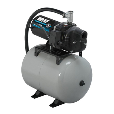
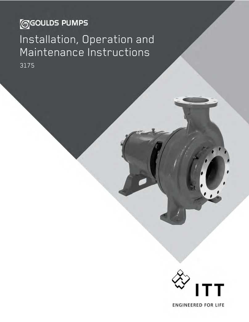
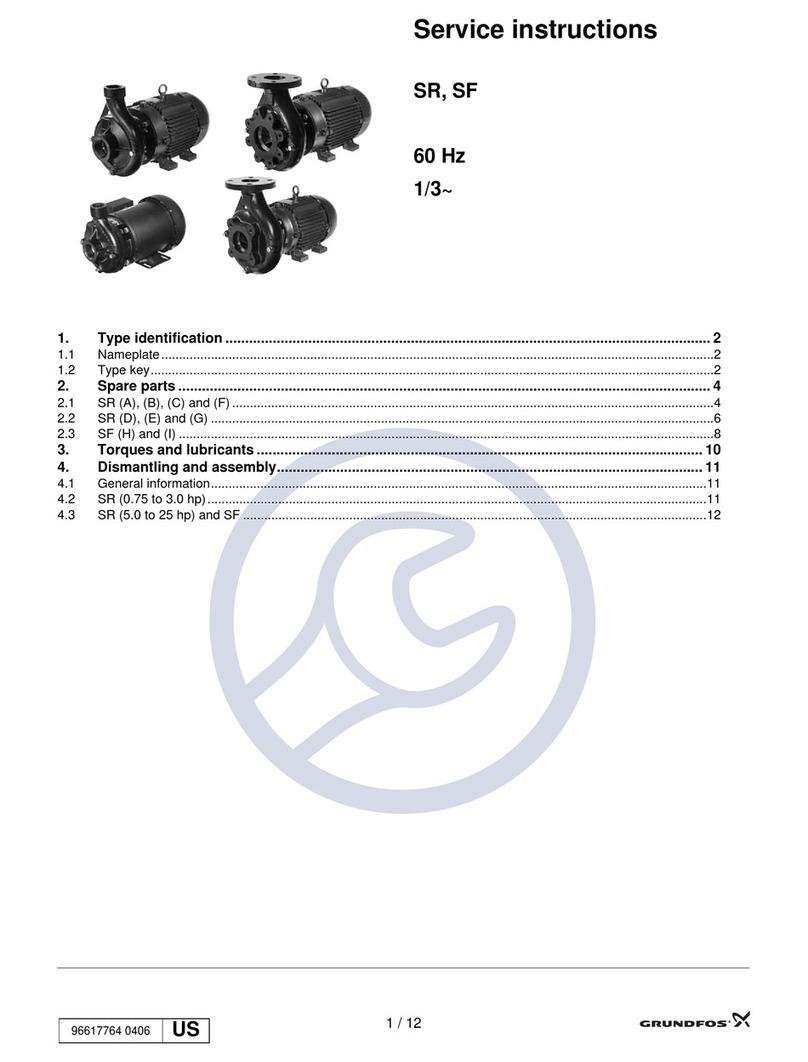
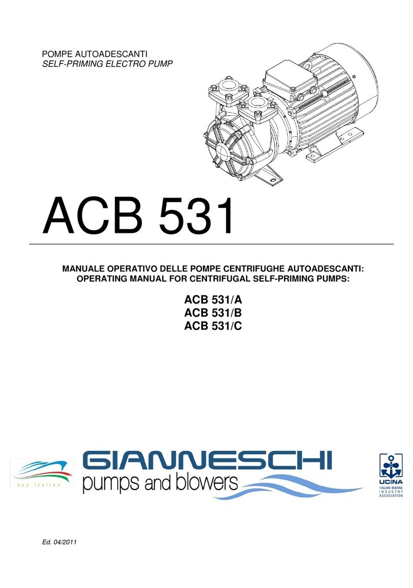
Simer 220515H User manual

I®
293 Wright Street, De[avan, W[ 53115
Phone: 1-800-468-7867
Fax: 1-800-390-5351
Web Site: SimerPump.com
22051514
OWNER'S MANUAL
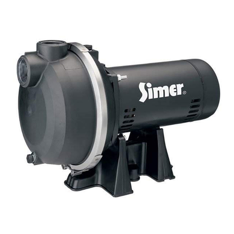
Shallow We[[ and Convertible
!/2 HP Jet Pump/Tank System
GUIDE D'UTILISATION
Syst_me de pompe _ 6iecteur
convertible et _ r&servoir de
!/2 CH pour puits peu profond
MANUAL DEE USUARIO
Sistema de tanque/bomba de
chorro convertible de !/2 tiP
para pozos poco profundos
Installation/Operation/Parts
For further operating, installation, or
maintenance assistance."
Call 1-800-468-7867
English ........... Pages 2-15
Installation/Fonctionnement/Pi_ces
Pour plus de renseignements
concernant /'uti/isation,
/'installation ou /'entretien,
Composer le 1 (800) 468-7867
Fran_ais ......... Pages 16-29
32051514
Instalaci6n/Operaci6n/Piezas
Para mayor informacidn sobre el
funcionamiento, instalacidn o
mantenimiento de la bomba:
Llame al 1-800-468-7867
Espaffol ....... Paginas 30-43
¢)2011 SIM934 (4/6/11 )

Safety 2
|mportant Safety |nstructions
SAVE THESE INSTRUCTIONS -This manual contains
important instructions that should be followed during
installation, operation, and maintenance of the product.
Save this manual for future reference.
This is the safety alert symbol. When you see this
symbol on your pump or in this manual, look for one of
the following signal words and be alert to the potential
for personal injury[
indicates a hazard which, if not avoided, will
result in death or serious injury.
[gWAFIN[NG[ indicates a hazard which, if not avoided,
could result in death or serious injury.
1_ CAUTION[ indicates a hazard which, if not avoided,
could result in minor or moderate injury.
NOTICE addresses practices not related to personal injury.
Carefully read and follow all safety instructions in thls
manual and on pump.
Keep safety labels in good condition.
Replace missing or damaged safety labels.
Electrical Safety
I_WARNiNG] Capacitor voltage may be hazardous.
To discharge motor capacitor, hold insulated handle
screwdriver BY THE HANDLE and short capacitor
terminals together. Do not touch metal screwdriver blade
or capacitor terminals. [f in doubt, consult a qualified
electrician.
General Safety
[_, CAUTION1Do not touch an operating motor. Modern
motors are designed to operate at high temperatures. To
avoid burns when servicing pump, allow it to cool for
20 minutes after shut-down before handling.
Do not allow pump or any system component to freeze.
To do so will void warranty.
Pump water only with this pump.
Periodically inspect pump and system components.
Wear safety glasses at all times when working on pumps.
Keep work area clean, uncluttered and properly lighted;
store properly all unused tools and equipment.
Keep visitors at a safe distance from the work areas.
[_WARNING] Pump body may explode if used as a
booster pump unless relief valve capable of passing full
pump flow at 75 psi is installed.
WARNING
Hazardous voltage.
Can shock, burn, or
cause death.
Ground pump before
connecting to power
supply. Disconnect power
before working on pump,
motor or tank.
_k Wire motor for correct
voltage. See "Electrical"
section of this manual
and motor nameplate.
_ round motor before
connecting to power
supply.
Meet Natlona[ Electrical
Code, Canadian
Electrical Code, and
local codes for all
wiring.
_Follow wiring
instructions in this
manual when
connecting motor to
power lines.
WARNING
Hazardous pressure!
Instal[ pressure relief
valve in discharge pipe.
Release all pressure on
system before working on
any component.

Warranty 3
Retain Original Receipt For Your Records
Limited Warranty
SIMERwarrantstotheoriginalconsumerpurchaser("Purchaser"or "You")ofitsproductsthattheyarefreefromdefectsinmaterialandworkmanship
foraperiodoftwelve(12)monthsfromthedateoftheoriginalconsumerpurchase.
If,withintwelve(12)monthsfromtheoriginalconsumerpurchase,anysuchproductshallprovetobedefective,itshallberepairedorreplacedat
SIMER'soption,subjecttothetermsandconditionssetforthbelow.Theoriginalpurchasereceiptandproductwarrantyinformationlabelarerequired
todeterminewarrantyeligibility.Eligibilityisbasedonpurchasedateoforiginalproduct- notthedateofreplacementunderwarranty.Thewarrantyis
limitedtorepairor replacementofproductonly- Purchaserpaysall removal,installation,labor,shipping,andincidentalcharges.
Forpartsortroubleshootingassistance,DONOTreturnproducttoyourretailstore.ContactSIMERCustomerServiceat1-800-468-7867.
Claimsmadeunderthiswarrantyshallbemadebyreturningtheproduct(exceptsewagepumps,seebelow)totheretailoutletwhereitwaspurchased
immediatelyafterthediscoveryofanyallegeddefect.SIMERwillsubsequentlytakecorrectiveactionaspromptlyasreasonablypossible.Norequests
forservicewill beacceptedif receivedmorethan30daysafterthewarrantyexpires.
Warrantydoesnotapplytoproductsusedincommercial/rentalapplications.
Sewage Pumps
DONOTreturnasewagepump(thathasbeeninstalled)toyourretailstore.ContactSIMERCustomerService.Sewagepumpsthathaveseenservice
andbeenremovedcarryacontaminationhazardwiththem.
Ifyoursewagepumphasfailed:
_, Wearrubbergloveswhenhandlingthepump;
_, Forwarrantypurposes,returnthepump'scordtagandoriginalreceiptofpurchasetotheretailstore;
_, Disposeofthepumpaccordingtolocaldisposalordinances.
Exceptions to the Twelve (12) Month Limited Warranty
Product
BW85P,CMIO,CMK,M40,M40P
2300,2310,2330,2520ULST,2943,2955,2956,2957,2960,5023SS,A5500
4" SubmersibleWell Pumps,2945,2958,2975PC,2985,3075%, 3983,3984
Pre-ChargeWaterSystemTank,3985,3986,3988,3989
3963,3995,3997
Warranty Period
90days
2Years
3Years
5Years
Lifetime
General Terms and Conditions
Youmustpayall laborandshippingchargesnecessarytoreplaceproductcoveredbythiswarranty.Thiswarrantydoesnotapplytothefollowing:(1)
actsofGod;(2)productswhich,in SIMER'ssolejudgement,havebeensubjecttonegligence,abuse,accident,misapplication,tampering,oralteration;
(3)failuresduetoimproperinstallation,operation,maintenanceorstorage;(4)atypicalorunapprovedapplication,useorservice;(5)failurescaused
bycorrosion,rustorotherforeignmaterialsin thesystem,oroperationatpressuresin excessofrecommendedmaximums.
ThiswarrantysetsforthSIMER'ssoleobligationandpurchaser'sexclusiveremedyfordefectiveproducts.
SIMERSHALLNOTBELIABLEFORANYCONSEQUENTIAL,INCIDENTAL,ORCONTINGENTDAMAGESWHATSOEVER.
THEFOREGOINGWARRANTIESAREEXCLUSIVEANDINLIEUOFALLOTHEREXPRESSANDIMPLIEDWARRANTIES,INCLUDINGBUTNOTLIMITED
TOTHEIMPLIEDWARRANTIESOFMERCHANTABILITYANDFITNESSFORA PARTICULARPURPOSE.THEFOREGOINGWARRANTIESSHALLNOT
EXTENDBEYONDTHEDURATIONPROVIDEDHEREIN.
Somestatesdonotallowtheexclusionorlimitationofincidentalor consequentialdamagesorlimitationsonhowlonganimpliedwarrantylasts,so
theabovelimitationsorexclusionsmaynotapplytoYou.ThiswarrantygivesYouspecificlegalrightsandYoumayalsohaveotherrightswhichvary
fromstatetostate.
SIMER " 293 Wright Street • Delavan, WI U.S.A. 531 IS
Phone: 1-800-468-7867. Fax" 1-800-390-5351 .Web Site: SimerPump.com

Installation - Shallow Well Pump 4
Suction Pipe
From Well
Valve
Priming
Teeand
Plug
Relief
To Household Drive
Water System Coupling
Typical pump Drive
shown herein. Point
Not to Scale.
6084 0909 "./
Figure I: Driven Point Installation
Suction Pipe
From Well
Priming
Teeand
Plug
To Household
Water System Relief
Valve
Sanitary Well Seal
Well Casing
At least f Foot
10' _ Valve
5-10' I Strainer
Figure 2: Cased Well Installation
Replacing An Old Pump
I_WARNING] Hazardous voltage. Disconnect power to pump before
working on pump or motor.
Step 1. Drain and remove the old pump. Check the old pipe for scale, lime,
rust, etc., and replace it if necessary.
Step 2.
Step 3.
Install the pump in the system. Make sure that all pipe joints in the
suction pipe are air-tight as well as water tight. If the suction pipe
can suck air, the pump will not be able to pull water from the well.
Adjust the pump mounting height so that the plumbing connections
do not put a strain on the pump body. Support the pipe so that the
pump body does not take the weight of piping or fittings.
You have just completed the well plumbing for your new pump.
Please go to Page 9 for electrical connections.
Well
Step 1.
Step 2.
Step 3.
Point (Driven Point) Installation (Figure I)
Drive the well, using "drive couplings" and a "drive cap". "Drive
fittings" are threaded all the way through and allow the pipe ends
to butt against each other so that the driving force of the maul is
carried by the pipe and not by the threads. The ordinary fittings
found in hardware stores are not threaded all the way through
the fitting and can collapse under impact. "Drive fittings" are
also smoother than standard plumbing fittings, making ground
penetration easier.
Mount the pump as close to the well as possible.
Use the fewest possible fittings (especially elbows) when connecting
the pipe from the well point to the pump suction port. The suction
pipe should be at least as large as the suction port on the pump
(include a check valve if your pump is not equipped with one - see
Figure 1). Support the pipe so that there are no dips or sags in the
pipe, so it doesn't strain the pump body, and so that it slopes slightly
upward from the well to the pump (high spots can cause air pockets
which can air lock the pump). Seal the threaded pipe joints with
'Teflon _Mtape or Teflon _Mbased pipe joint compound approved for
use on PVC. Joints must be air- and water-tight. If the suction pipe
can suck air, the pump cannot pull water from the weft. If one well
point does not supply enough watec consider connecting two or
three well points to one suction pipe.
1 E. L DuPont de Denlours and Coml)auy Corl)oration, Delaware
You have just completed the suction piping for your new pump.
Please go to Page 9 for electrical connections.
Cased Well Installation, 2" or Larger Casing
(Figure 2)
Step 1. Mount the pump as close to the well as possible.
Step 2. Assemble the foot valve, strainer, and well pipe (see Figure 2). Make
sure that the foot valve works freely.
Step 3. Lower the pipe into the well until the strainer is five feet above the
bottom of the well. [t should also be at least 10 feet below the well's
water level while the pump is running in order to prevent the pump
from sucking air. Install a sanitary well seal.

Installation - Shallow Well Pump 5
Step 4. Install a priming tee, priming plug, and suction pipe to the pump
(see Figure 2). Connect the pipe from the well to the pump suction
port, using the fewest possible fittings - especially elbows - as
fittings increase friction in the pipe (however, include a foot valve
- see Figure 2). The suction pipe should be at least as large as the
suction port on the pump. Support the pipe so that there are no
dips or sags in the pipe, so it doesn't strain the pump body, and
so that it slopes slightly upward from the well to the pump (high
spots can cause air pockets which can air lock the pump). Seal the
suction pipe joints with Teflon _Mtape or a Teflon _Mbased pipe joint
compound. Joints must be air- and water-tight.
If the suction pipe can suck air, the pump cannot pull water from
the weft.
You have just completed the suction piping for your new pump.
Please go to Page 9 for electrical connections.
Sealing Pipe Joints
Use only Teflon _Mtape or Teflon 'M based joint compounds for
making all threaded connections to the pump itself. Do not
use pipe joint compounds on plastic pumps: they can react
with the plastic in pump components. Make sure that all pipe
joints in the suction pipe are air tight as well as water tight. If
the suction pipe can suck air, the pump will not be able to puff
water from the well.

Replacing an Existing Convertible Pump 6
Shallow Well
ReplaceRegulator
with:
1" Pipe Plug*
1" "_Q
1" Nippl,
Deep Well
Pressure
Regulator G _ge
....9
* PurchaseSeparately 5985 0409
Figure 4: Install Pressure Regulator
and Gauge for deep well Install
Priming Tee and Gauge for
shallow well
up through the
SuctionPipe
to Pump Suction
Figure 5: Drive and Suction Functions
59800211
Figure 6: Mount Ejector _Shallow Well
Deep Well
[&WARNING]Hazardous voltage. Disconnect power to pump before working
on pump or motor.
Step 1. Drain and remove the old pump. Check pipe for scale, lime, rust,
etc., and replace it if necessary.
Step 2. install the pressure regulator and pressure gauge in the pump body
(see Figure 4).
NOTICE: Your old ejector (in the well) may not be properly matched
to your new pump. If the pump does not perform
properly, we recommend that you install ejector kit FP520-100-P2,
included with the pump.
Step 3. install the pump and tank in the system. Make sure that all pipe
joints in the suction pipe are air-tight as well as water tight. If the
suction pipe can suck aic the pump will not be able to pull water
from the well.
Step 4. Adjust the pump mounting height so that the plumbing connections
do not put a strain on the pump body. Support the pipe so that the
pump body does not take the weight of piping or fittings.
Step 5. Run piping from the discharge tee in the tank flange to the household
piping. The discharge piping must be at least as large as the tank
tee. install a relief valve in the discharge pipe capable of passing the
entire pump flow at 75 psi. Run a pipe from the relief valve to a floor
drain or some other convenient place to carry off the water.
You have just completed the well plumbing for your new pump/tank
system. Pleasego to Page 9 for electrical connections.
Shallow Well-(Convertible-See Page 4 for Shallow
Well Pump)
[_WARNINel Hazardous voltage. Disconnect power to pump before working
on pump or motor.
Step 1. Drain and remove the old pump. Check the old pipe for scale, lime,
rust, etc., and replace it if necessary.
Step 2. Remove the pressure regulator from the pump body. Replace it with
a 1" NPT close nipple, a l"xl"x3/4" NPTTee, and a 1" NPT pipe
plug (see Figure 4). install the pressure gage in the plugged hole in
the pump body (see Figure 4).
Step 3. install the ejector kit. Follow the instructions provided with the kit.
Be sure to align the ventun with the top hole on the front of the
pump (see Figure 6).
NOTICE: Always replace the ejector when replacing the pump in a
shallow well installation.
Step 4. Install the pump and tank in the system. Make sure that all pipe
joints in the suction pipe are air-tight as well as water tight. If the
suction pipe can suck aic the pump will not be able to pull water
from the well.
Step 5. Adjust the pump mounting height so that the plumbing connections
do not put a strain on the pump body. Support the pipe so that the
pump body does not take the weight of piping or fittings.
Step 6. Run piping from the discharge tee in the tank flange to the household
piping. The discharge piping must be at least as large as the tank
tee. install a relief valve in the discharge pipe capable of passing the
entire pump flow at 75 psi. Run a pipe from the relief valve to a floor
drain or some other convenient place to carry off the waten
You have just completed the weft plumbing for your new pump/tank
system. Please go to Page 9 for electrical connections.

New Shallow Well Convertible Pump Installation 7
Replace Pressure
Regulator with
Priming Tee
(see fig. 1)
Suction Pipe
Well
Priming
Tee and
Plug
To Household
Water System Sanitary /
Well Seal
Well
Casing
At least
10'
5-10'
5974 0309
Figure 7: Cased Well Installation
Replace Pressure
Regulator with
Priming Tee
(see fig. 1)
Suction Pipe
From Well
Priming
Teeand
Plug
Check
Valve
To Household Drive
Water System Coupling
Drive
Point
5988 0409
Figure 8: Driven Point Installation
Shallow Well Installations
Step 1. Remove the control valve from the pump body. Replace it with a
1" NPT close nipple, a l"xl"x3/4" NPT Tee, and a 1" NPT pipe
plug (see Figure 1). Install the pressure gage in the plugged hole in
the pump body (see Figure 4).
Step 2. Install the ejector kit. Follow the instructions provided with the kit.
Align the venturi with the top hole on the front of the pump (see
Figure 6).
Cased Well Installation, Z' or Larger Casing
(Figure 7)
Step .3. Mount tile pump as close to tile well as possible. Connect tile pipe
from the well to the pump suction port, using the fewest possible
fittings - especially elbows - as fittings increase friction in the pipe.
Step 4. Assemble the foot valve, strainer, and well pipe (see Figure 7). Make
sure that the foot valve works freely.
Step 5. Lower the pipe into the well until the strainer is five feet above
the bottom of the well. It should also be at least 10 feet below the
well's water level while the pump is running in order to prevent the
pump from sucking air. Install a sanitary well seal.
Driven Point Installation (Figure 8)
Step .3. Drive the well, using "drive couplings" and a "drive cap". "Drive
fittings" are threaded all the way through and allow the pipe ends
to butt against each other so that the driving force of the maul is
carried by the pipe and not by the threads. The ordinary fittings
found in hardware stores are not threaded all the way through
the fitting and can collapse under impact. "Drive fittings" are
also smoother than standard plumbing fittings, making ground
penetration easier.
Step 4. Mount the pump as close to the well as possible.
Step 5. If one well point does not supply enough water, consider
connecting two or three well points to one suction pipe.
All Shallow Well Installations
Step 6. Install a priming tee, priming plug, and suction pipe to the pump
(see Figures 7 and 8). Connect the pipe from the well to the pump
suction port, using the fewest possible fittings - especially elbows -
as fittings increase friction in the pipe.
•The suction pipe should be at least as large as the suction port on
the pump (include a check valve - see Figures 7 and 8).
• Support the pipe so that there are no dips or sags in the pipe,
so it doesn't strain the pump body, and so that it slopes slightly
upward from the well to the pump (high spots can cause air
pockets which can air lock the pump).
Seal the pipe joints with Teflon _Mtape or Teflon-based _Mpipe
joint compound. Joints must be air- and water-tight. If the suction
pipe can suck air, the pump cannot pull water from the well.
Step 7. Run piping from the discharge tee in the tank flange to the household
piping. The discharge piping must be at least as large as the tank
tee. Install a relief valve in the discharge pipe capable of passing the
entire pump flow at 75 psi. Run a pipe from the relief valve to a floor
drain or some other convenient place to carry off the water.
You have just completed the piping for your new pump/tank system.
Please go to Page 9 for electrical connections.

New Deep Well Convertible Pump Installation 8
Pressure Regulator,
Gauge, and Priming Suction (Larger)
Plug Pipe from Well
Drive (Smaller)
Pipe to Well
To Household Valve
Water System
Well
Head
Venturi
Ejector
Foot Valve
Figure 9: 4" and Larger Deep Well
Pressure Regulator, Suction (Larger)
Gauge, and Priming Pipe from Well
Plu( Drive (Smaller)
Pipe to Well
Casing
)ter
To Household Valve
Water System
Suction Pipe
Well Casing
serves as
Drive Pipe
Venturi
Nozzle
Ejector
4" Or Larger Well (Figure 9)
Step 1. Install the pressure regulator and pressure gauge in the pump body.
See Figure 4, Page 6.
Step 2. Assemble the ejector kit. See Figure 9. Follow the instructions
included with the kit in order to match the nozzle and venturi to
your well conditions.
Step 3. Mount the pump as close to the well as possible.
Step 4. Connect two pipes (1" drive, 1-1/4" suction) to the ejector and
lower the ejector into the well until it is five feet from the bottom.
It should also be at least 10 feet below the well's water level while
the pump is running in order to prevent the pump from sucking air.
Step 5. Install a sanitary well seal and connect the ejector piping to the
pump. Use steel nipples through the well seal with flexible poly
pipe to avoid crushing the plastic pipe when tightening the seal.
Step 6. Support the pipe so that there are no dips or sags in the pipe, so it
doesn't strain the pump body, and so that it slopes slightly upward
from the well to the pump (high spots can cause air pockets which
can air lock the pump). Seal the pipe joints with Teflon _Mtape or a
Teflon_M-based pipe joint compound. Joints must be air- and water-
tight. If the suction pipe can suck aic the pump cannot pull water
from the well.
Step 7. Run piping from the discharge tee in the tank flange to the household
piping. The discharge piping must be at least as large as the tank
tee. Install a relief valve in the discharge pipe capable of passing the
entire pump flow at 75 psi. Run a pipe from the relief valve to a floor
drain or some other convenient place to carry off the water.
You have just completed the plumbing for your new pump. Please go to
Page 9 for electrical connections.
2" Well (Figure I O)
Step 1. Install the pressure regulator and pressure gauge in the pump body.
See Figure 4, Page 6.
Step 2. Mount the pump as close to the well as possible.
Step 3. Assemble ejector kit, well piping, and well head adapter according
to the instructions provided with the ejector package. See Figure 1 0.
Use galvanized drop pipe with turned couplings to allow proper
flow. Follow the instructions included with the kit in order to match
the nozzle and venturi to your well conditions.
Step 4. Run two pipes (one smaller drive pipe, one larger suction pipe)
from the well to the pump. Support the pipe so that there are no
dips or sags in the pipe, so it doesn't strain the pump body, and so
that it slopes slightly upward from the well to the pump (high spots
can cause air pockets which can air lock the pump). Seal the pipe
joints with Teflon _Mtape or a Teflon_M-based pipe joint compound.
Joints must be air- and water-tight. If the suction pipe can suck aic
the pump cannot pull water from the well.
Step 5. Run piping from the discharge tee in the tank flange to the household
piping. The discharge piping must be at least as large as the tank
tee. Install a relief valve in the discharge pipe capable of passing the
entire pump flow at 75 psi. Run a pipe from the relief valve to a floor
drain or some other convenient place to carry off the water.
You have just completed the plumbing for your new pump. Please go to
Page 9 for electrical connections.
NOTE: The ejector kit supplied with your pump tank system will not work
with a 2" well. You must purchase kit part number FPAV2-V2 separately.
Figure I0: 2"'(Single Pipe) Deep Well

Electrica- All Models 9
Disconnect power before working on pump, motor, pressure switch, or wiring.
1_ CAUTION ]Risk of fire. Never wire a 115 volt motor to a 230 volt line.
Check Voltage Setting.
1. Turn off power to the pump!
2. Determine if the power supplied to the pump is 115
or 230 volts.
3. A qualified person must install electrical wiring.
4. The voltage switch is factory set to 115 volts. If you
have 115 volt service, do not change the selection.
1/2 HP motors are preset at the factory for 115 volts.
5. To change the voltage (if necessary), remove the
motor capacitor cover and slide the switch fully to
the correct voltage.
6. Reinstall the cover.
Do Not Turn On Power Yet r.
_[___rTo Motor
Connection_--_(_ ,,___.,H _f_
From Line-
5907 1108
Figure I I: Connect power supply wires to pressure
switch as shown.
Connect Power Supply Wiring
To Pressure Switch
1. Remove the pressure switch cover.
2. Attach power and ground wires to the pressure
switch as indicated.
3. Reinstall the cover.
Do Not Turn On Power Yet!
Figure 12A: Remove cover from capacitor box to
reach voltage change slide switch.
Figure 12B: Pump is shipped from factory set for
115-volt operation (above). To change to 230-volt
operation, slide switch to display "230" (below).
5982 0409
Figure 12C: Slide switch set for 230-volt operation.

Electrical - All Models I 0
[,_.WARNING IHazardous voltage. Can shock, burn, or kill Connect ground
wire before connecting power supply wires. Use the wire size (including
the ground wire) specified in the wiring chart. [f possible, connect the
pump to a separate branch circuit with no other appliances on it.
[AWARNING] Expiosion hazard. Do not ground to a gas supply line.
Wiring Connections
[_i_WARNING] Fire hazard. Incorrect voltage can cause a fire or seriously
damage the motor and voids the warranty. The supply voltage must be
within _+10% of the motor nameplate voltage.
NOTICE: The motor is factory wired for 115 volts. [f necessary, reconnect
the motor for 230 volts, as shown in Figures 12A, 12B, and 12C. Do not
attempt to operate the pump as it comes from the factory on 230 volts.
Install, ground, wire, and maintain your pump in compliance with the
National Electrical Code (NEC) or the Canadian Electrical Code (CEC), as
applicable, and with all local codes and ordinances that apply. Consult
your local building inspector for code information.
Connection Procedure:
Step 1. Connect tile ground wire first as shown in Figure 1 1. The ground
wire must be a solid copper wire at least as large as the power
supply wires.
Step 2. There must be a solid metal connection between the pressure
switch and the motor for motor grounding protection. If the pressure
switch is not connected to the motoc connect the green ground
screw in the switch to the green ground screw under the motor end
cover. Use a solid copper wire at least as large as the power supply
wires.
Step 3.
Step 4.
Connect the ground wire to a grounded lead in a service panel,
to a metal underground water pipe, to a metal weil casing at least
ten feet (3M) long, or to a ground electrode provided by the power
company or the hydro authority.
Connect the power supply wires to the pressure switch as shown in
Figure 11.
You have just completed the wiring for your pump.
Pleasego to Page11 or 12 for startup preparations.
Model
220515H
320515H
Motor HP
1/2
1/2
Volts
115/230
115/230
Wiring Chart - Recommended Wire and Fuse Sizes
Nameplate
Amps
8.5/4.2
7.0/3.5
Branch Fuse
Rating Amp
15
15
DISTANCE IN FEET FROM MOTOR TO SUPPLY
0-100 101 - 200 201 - 300 301 - 400
AWG WIRE SIZE (ram 2)
14/14 (2/2) 12/14 (3/2) 10/14 (5.5/2) 8/14 (8.4/2)
14/14 (2/2) 12/14 (3/2) 10/14 (5.5/2) 10/14 (5.5/2)

Preparing to Start the Deep Well Pump I I
Remove pressure
regulator and fill
pump and
suction piping
throuc
discharge port.
Figure 13: Fill Pump
Replace pressure
regulator and all fill
plugs, reconnect the
hose, and close
the regulator
completely
Figure 14: Prime Pump
5978 0309
I_CAUTION INever run pump dry. Running pump without water may cause
pump to overheat, damaging seal and possibly causing burns to persons
handling pump. Fill pump with water before starting.
[_i_WARNING]Never run pump against closed discharge. To do so can boil
water inside pump, causing hazardous pressure in unit, risk of explosion
and possibly scalding persons handling pump.
Step 1. Open the pressure regulator as far as possible without backing it
out of the regulator body. Then remove the regulator from the pump
and fill the pump, fill all piping between the pump and the well,
and make sure that all piping in the well is full. If you have also
installed a priming tee in the suction piping, remove the plug from
the tee and fill the suction piping (see Figure 13).
Step 2. Replace all fill plugs and close the pressure regulator completely
(Figure 14).
Step 3. Power on! Start the pump and watch the pressure gauge. The
pressure should build rapidly to about 50 PSI as the pump primes.
Step 4.
Step 5.
Step 6.
After 2 or 3 minutes, the gauge should show pressure. If not, stop
the pump, remove the fill plugs, reopen the control valve, and refill
the pump and piping. Y()u may have to repeat this two or three
times in order to get all the trapped air out of the piping. Don't for-
get to close the control valve each time before you start the pump.
When pressure has built up and stabilized at about 50 PSI, slowly
open the control valve (see Figure 15) and let the pressure drop
until the pressure gauge needle starts to flutter or drops to 0. When
the needle flutters or drops, close the valve iust enough to stop the
flutter or bring the needle back to a stable pressure (see Figure 15).
Y()ur pump is now operating at its most efficient point.
After the pump has built up pressure in the system and shut off,
check the pressure switch operation by opening a faucet or two
and running enough water out to bleed off pressure until the pump
starts. The pump should start when pressure drops to 30 PSI and
stop when pressure reaches 50 PSI. Run the pump through one or
two complete cycles to verify correct operation. This will also help
clean the system of dirt and scale dislodged during installation.
A-SLOWLYopen Pressure Regulator Congratulations on asuccessful installation.
If you were unsuccessful, please refer to the Troubleshooting section or call
our customer service technical staff.
B-Watch for Gaugeto Flatter orDrop
C-CI0sePressureRegulatoruntilPressure
Stabilizes 5979 0309
Figure 15: Set Control Valve

Preparing to Start the Shallow We[[ Pump [2
Remove fill
plug and fill pump
and suction piping
through priming tee. '''_
Figure 16: Fill Pump through
Priming Tee
I_ CAUTION[ Never run pump dry. Running pump without water may cause
pump to overheat, damaging seal and possibly causing burns to persons
handling pump. Fill pump with water before starting.
[_,WARNING]Never run pump against dosed discharge. To do so can boil
water inside pump, causing hazardous pressure in unit, risk of explosion
and possibly scalding persons handling pump.
Step 1. Remove the priming plug from the pump and fill the pump, fill
all piping between the pump and the well, and make sure that all
piping in the well is full (see Figure 16). if you have also installed a
priming tee in the suction piping, remove the plug from the tee and
fill the suction piping.
Replace all fill plugs.Step 2.
Step 3. Power on! Start the pump. The pump should pump water in two or
three minutes.
Step 4.
Step 5.
If you don't have water after 2 or 3 minutes, stop the pump and
remove the fiil plugs. Refill the pump and piping. You may have to
repeat this two or three times in order to get all the trapped air out
of the piping.
After the pump has built up pressure in the system and shut off,
check the pressure switch operation by opening a faucet or two
and running enough water out to bleed off pressure until the pump
starts. The pump should start when pressure drops to 30 PSI and
stop when pressure reaches 50 PSI. Run the pump through one or
two complete cycles to verify correct operation. This will also help
clean the system of dirt and scale dislodged during installation.
Congratulations on asuccessful installation.
if you were unsuccessful, please refer to the Troubleshooting section or call
our customer service technical staff.

Troubleshooting 13
Symptom
Motor will not run
Motor runshot and overload
kicks off
Motor runs but nowater is
delivered*
* Stop pump; then check
prime before Iooldng for
other causes. Unscrew
priming plug and see if
water is in priming hole.
Pump does not deliver water
to full capacity (Also check
point ¢ immediately above)
Pump delivers water but does
not shut off or pump cycles
too frequently
Air spurts from faucets
Possible Cause(s)
Disconnect switch is off
Fuse is blown or circuit breaker tripped
Starting switch is defective
Wires at motor are loose, disconnected, or
wired incorrectly
Pressure switch contacts are dirty
Motor is wired incorrectly
Voltage is too low
Pump cycles too frequently
Pump in new installation did not pick up
prime through:
1. Improper priming
2. Air leaks
¢. I ealdng foot valve or check valve
Pump has lost prime through:
1. Air leaks
2. Water level below suction pipe inlet
Foot valve or strainer is plugged
Ejector or impeller is plugged
Check valve or foot valve is stuck shut
Pipes are frozen
Foot valve and/or strainer are buried in
sand or mud
Water level is too low for shallow well
setup to deliver water
Water level in well is lower than estimated
Corrective Action
Be sure switch is on.
Replace fuse or reset circuit breaker.
DISCONNECT POWER; Replace starting switch.
Refer to instructions on wiring (Page 9). DISCONNECT POWER; check and
tighten all wiring.
I,_WAFINING l Cal)acitor voltage may, be hazardous. To discharge capacitor,
hold insulated handle screwdriver BY THE HANDLE and short capacitor
[ terminals together. Do not touch metal screwdriver [)lade or capacitor terminals.
If in doubt, consult a qualified electrician.
DISCONNECT POWER and file contacts with emery board or nail file.
Refer to instructions on wiring.
Check with power company. Install heavier wiring if wire size is too small (See
Electrical /Wiring Chart).
See section below on too frequent cycling.
In new installation:
1. Re-prime according to instructions.
2. Check all connections on suction line, AVC, and ejector with soapy water or
shaving cream.
_¢.Replace foot valve or check valve.
In installation already in use:
1. Check all connections on suction line and shaft seal.
2. lower suction line into water and re-prime. If receding water level in well
exceeds 25' (7.6M), a deep well pump is needed.
Clean foot valve or strainer.
Clean ejector or impeller.
Replace check valve or foot valve.
[ Thaw pipes. Bury pipes below frost line. Heat pit or pump house.
Raise foot valve and/or strainer above bottom of water source. Clean foot valve
and strainer.
A deep well jet will be needed if your well is more than 25' (7.6M) depth to
water.
A new nozzle and venturi combination may be needed.
Steel piping (if used) is corroded or limed,
causing excess friction
Piping is too small in size
Pressure switch is out of adjustment or
contacts are welded together
Faucets have been left open
Venturi, nozzle or impeller is clogged
Standard pressure tank is waterlogged and
has no air cushion
Pipes leak
Foot valve leaks
Pressure switch is out of adjustment
Air charge too low in pre-charged tank
Pump is picldng up prime
leak in suction side of pump
Well is gaseous
Intermittent over-pumping of well. (Water
drawn down below foot valve.}
Replace with plastic pipe where possible, otherwise with new steel pipe.
Use larger piping.
DISCONNECT POWER;adjust or replacepressureswitch.
Close faucets.
Clean venturi, nozzle or impeller.
Drain tank to air volume control port. Check AVC for defects. Check all
connections for air leaks.
Check connections.
Replace foot valve.
Adjust or replace pressure switch.
DISCONNECT POWER and open faucets until all pressure is relieved. Using
i tire pressure gauge, check air pressure in tank at valve stem located on the tank.
If less than pressure switch cut-in setting (30-50 PSI), pump air into tank from
outside source until air pressure is 2 PSI less than cut-in setting of switch. Check
air valve for leaks {use soapy solution) and replace core if necessary.
I When pump has picked up prime, it should pump solid water with no air.
Suction pipe is sucldng air. Check joints for leaks with soapy water.
Consult factory about installing a sleeve in the well.
lower foot valve if possible, otherwise restrict pump discharge.

Repair Parts [ 4
..............................9.................... j s .,ow
1./12 ............................................
13 15 ............................
_- */ 14 x, ............. 6
I
I
9 10 ......11..12 15
L.
Key Part Key Part Key Part
No. Description Qty. No. Description Qty. No. Description Qty.
1
1A
2
3
4
5
6
7
Motor/Seal Plate Assembly 1
Motor Flange Screw 4
Seal Plate O-Ring 1
Pressure switch 1
Shaft Seal 1
Impeller 1
1/4" NPT x 1/4" Barb Elbow 2
Hose 1
8 Diffuser
9 Diffuser Plate
10 Diffuser Plate O-Ring
11 Diffuser Plate Washer
12 Diffuser Plate Screw
13 Venturi
14 Nozzle
15 Pump Body
1
1
1
3
3
1
1
1
15A Pressure Regulator
16 Ejector Gasket
17 Ejector Body
18 Washer
19 Ejector Capscrew
1
1
1
2
2
Part
Description
Sealand (-)-Ring Kit
Overhaul [{it
Ejector Kit
Pump Body Assembly
Pressure Switch (30-50)
Pressure Switch Tubing
Pressure Regulator
Kits Include:
Seal and O-Ring [(it:
Overhaul Kit (Shallow well)
Overhaul [(it (Convertible)
Ejector [(it (Convertible)
Pump Body Assembly (Convertible)
Pump Body Assembly (Shallow well)
Pressure Switch
Pressure Switch Tubing Kit
Pump Model and Horsepower
Convertible (Deep Well) Pumps
320515H
1/2 HP
RPK-35
RPK-205DW
FP520-100
R176-72
TC2151
FPASFK
FPAPR
Shallow Well Pumps
220515H
1/2 HP
RPK-35
RPK-205SW
R176-73
TC2151
FPASFK
Key Nos2,4, 10, 16
Key No8 1A, 2, 4, 5, 8, 9, 11(3), 12(3), 13, 14
Key Nos 1A, 2, 4, 5, 8, 9, 10, 11, 12
Key Nos 6(2), 7, 13(5), 14(2), 16, 17, 18(2), 19(2)
Key Nos2, 6, 10, 15, 16, 1/4" NPT Plug(2), 1/2" NPT Plug
Key No82, 6, 13, 14, 15, 1/4" NPT Plug(2), 1/2" NPT Plug
Key No 3
Key No8. 6(3), 7

Repair Parts 15
11 _\
l
9
1D
Key Part
No. Description Qty. 320515H
1A Pressure Regulator 1 FPAPR
1B Discharge Cross 1 -
1C Reducer Bushing 1/2" NPT x 1/8" NPT 1 -
1D Pipe Plug 1" NPT 1 -
,, Pipe Plug 1/8" NPT 1 -
2 Pressure Gauge 1 rc2104
3 3/4" NPT x 1" Hose Barb 90° Elbow 1 U78-770P
4 1" Hose Clamp 2 U19-55SS
5 1" Hose 1 U74-37R
6 3/4" NPT x 1" Hose Barb Adapter 1 24206A004
7 3/4" NPT x 3/4" NPT x 3/4" NPT Street Tee 1 05002A001
8 5/16"-18 Hanged Nuts 6 U36-202BT
9 rank Flange 1 U31-442P
o rank Bladder 1 U20-7
10 rank Body 1 *
11 Air Valve with Cap 1 U212-160
220515H
U78-961P
U78-107PT
U78-1008P
WC78-41 T
-rc2104
U19-55SS
U74-37H
24206A 004
05002A001
U36-202 BT
U 31-442 P
U20-7
U212-160
* If tank body fails, replace entire tank (Part Number RT6H).
o Not illustrated.

S6curit6 16
Directives de s6curit6 importantes
Conservez cos directives- Ce manuel renferme d'importantes
directives qu'il faut suivre durant I'installation et I'entretien de
la pompe.
Ce symbole _. indique qu'il faut _tre prudent. Lorsque ce
symbole apparatt sur la pompe ou dans cette Notice, rechercher
une des raises en garde qui suivent, car dies indiquent un
potentiel de blessures corporelles!
Le mot signal _ indique un danger qui, s'il n'est pas
6vit6, causera la mort ou des blessures graves.
Le mot signal E_,AWRTISSEMENT]indique un risque qui, s'il n'est
pas 6vit6, pourrait causer la mort ou des blessures graves.
Le mot signal E_.A'rTENTION] indique un risque qui, s'il n'est pas
6vit6, pourrait causer des blessures mineures ou mod6r6es.
Le mot AVIS est utilis6 pour los pratiques qui ne sont pas reli6es
aux blessures personnelles.
Lire attentivement toutes les consignes de s_curit_ contenues darts
cette Notice ou collies sur la pompe.
Garder los autocollants de s6curit6 en bon 6tat;
los remplacer s'ils manquent ou s'ils ont 6t6 endommag6s.
S6curit6 concernant 1'61ectricit6
I_AVERTIISSEMENTI La tension du condensateur pout _tre
dangereuse. Pour d6charger le condensateur du moteur, tenir
un tournevis _ manche iso[6 PAR LE MANCHE et mettre en
court-circuit los bornes du condensateur. Ne pas toucher la lame
m6tallique du tournevis ni los bornes du condensateur. En cas de
doute, consulter un 6[ectricien qualifi6.
S_curit_ g_n6rale
I_ATTENTIONI Ne pas toucher un moteur qui fonctionne.
Los moteurs modernes sont con_us pour fonctionner par
des temp6ratures 61ev6es. Pour ne passe br01er Iorsque I'on
interviendra sur la pompe, la laisser refroidir pendant 20 minutes
aprbs I'avoir arr6t6e avant de la toucher.
Ne pas hisser geler la pompe ni aucun autre 616ment du syst6me,
sinon la garantie sera annulde.
Ne pomper que de I'eau avec cette pompe.
Pdriodiquement, inspector la pompe et tous los 616ments
du syst.gme.
Toujours porter des lunettes de sdcuritd Iorsque I'on intervient sur
une pompe.
Garder la zone de travail propre, non encombrde et bien 6clairde;
tous los outils et tout 1'6quipement non utilisds doivent 6tre
entreposds correctement.
Ne pas laisser los visiteurs s'approcher de la zone de travail.
I&AVERT|SSEMENTI Le corps de la pompe peut exploser si la
pompe est utilis(_e en rant que pompe de surpression, _ moins
qu'une soupape de sOret6 pouvant laisser passer le d6bit maximum
de la pompe _ 75 Ib/po 2 soit pos6e.
_. AVERTISSEMENT
Tension dangereuse.
Risque de secousses
61ectriques, de brOiures,
voire de mort.
Mettre a la terre la pompe
avant de la brancher sur le
courant electrique. Couper
I'arrivee de courant avant
d'intervenir sur la pompe, sur
le moteur ou sur le reservoir.
_k CSbler le moteur en
fonction de la bonne
tension. Volt la Section
_ltlectricit6_ de cette
Notice et Maplaque
slgna[6tique du moteur.
_h ettre _ [a torte le
moteur avant de le
brancher sur le courant
6[ectrlque.
_ Conforme au Code
national de 1'61ectrlcit6,
au Code canadien de
l'6lectricit6 et aux codes
munlcipau× pour tous
les c_blages.
_k especter los instructions de c_blage figurant dans
cette Notice Iorsque I'on branche le moteur sur
une llgne haute tension.
,_ AVERTISSEMENT
Pression dangereuse!
Poser une soupape de sOret&
sur le tuyau de refoulernent.
Dissiper toute la pression
du systeme avant d'intervenir
sur un el6ment.

Garantie I 7
Conserver I'original du re¢;u pour route r&f&rence ult&rieure
Garantie limit_e
SIMERgarantita I'acheteur/auconsommateurd'origine(l'Acheteur)quesesproduitssontexemptsdetoutvicedemateriauetdefabrication.Cette
garantieestvalablependantdouze(12)moisa partirdeladated'achatd'origine.
Si,danslesdouze(12)moissuivantladated'achatd'origine,unproduitsereveled@ectueux,il serarepareouremplace,a ladiscretiondeSIMER,
conformementauxmodalitesetconditionsexposeesci-dessous.Lerqu deI'achatd'origineetI'@iquetted'informationsurlagarantiesontrequispour
determinerla recevabilitedelareclamationautitredelagarantie.LarecevabilitedelareclamationsebasesurladatedeI'achatd'origineduprod@t,et
nonsurladated'uneve@u@remplacementsousgarantie.Lagarantieestlimiteea lareparationouauremplacementduproduituniquement.L'Acheteur
assumelesfraisderetrait,d'installation,detransportettouslesfraisaccessoires.
PourobtenirdespiecesoudeI'aidetechnique,NEPASretournerleproduitaud@aillant.ContacterleservicealaclienteledeSIMER
au1-800-468-7867.
Lesreclamationsautitredecettegarantiedoivent@reeffectueesenretournantleproduit@I'exceptiondespompesd'eauxd'egout,voirci-dessous)au
d@aillantoi il aeteachete,etce,immediatementap@sladecouvertedeladefaillancesupposee.SIMERprendralesmesurescorrectivesnecessaires
dansundelairapideetraisonnable.Aucunedemandedereparationneseraaccepteeplusde30joursap@sI'expirationdelagarantie.
Cettegarantienes'appliquepasauxproduitsutilisesadesfinscommercialesoudelocation.
Pompes d'eaux d'_gout
NEPASRETOURNERunepomped'eauxd'egout(quiaeteinstallee)aud@aillant.CommuniqueravecleservicealaclienteledeSIMER.Lespompes
d'eauxd'egoutquionteteutilisees,puisretireespresententunrisquedecontamination.
Encasdedefaillancedelapomped'eauxd'egout:
• Porterdesgantsencaoutchoucpourmanipulerlapompe.
• Adesfinsdegarantie,retournerI'@iquettefigurantsurlecordondelapompeetI'originaldur%uaud@aillant.
• Mettrelapompeaurebutconformementa lareglementationlocale.
Exceptions _ la garantie limit_e de douze (I 2) mois
Produit P_riode de garantie
BW85P,CMIO,CMK,M40,M40P 90jours
2300,2310,2330,2520ULST,2943,2955,2956,2957,2960,5023SS,A5500 2ans
Pompepourpuitssubmersiblesde4 pouces,2945,2958,2975PC,2985,3075%, 3983,3984 3ans
%sewoirp@charg6desyst_med'eau,3985,3986,3988,3989 5 ans
3963,3995,3997 Avie
Noclalit_s et conditions g&n&rales
L'Acheteurdoitpayertouslesfraisdemaind'ceuvreetdetransportnecessairesauremplacementduproduitgaranticouvertparcettegarantie.
Cettegarantienes'appliquepasa cequisuit:(1)Lescatastrophesnaturelles;(2)Lesproduitsqui,selonSIMER,ontfaitI'objetd'unenegligence,
d'uneutilisationabusive,d'unaccident,d'unemauvaiseapplicationoud'unealteration;(3)Lesdefaillancesduesa uneinstallation,une
utilisation,unentretienouunentreposageinappropries;(4)Uneapplication,uneutilisationouunereparationatypiqueounonapprouve;(5)Les
d@aillancescauseesparlacorrosion,larouilleoud'autresmateriaux@rangersausysteme,ouparuneutilisationaunepressionsuperieureau
maximumrecommande.
Cettegarantie@ablitlaresponsabiliteuniquedeSIMERetlerecoursexclusifdeI'Acheteurencasdeproduitdefectueux.
SIMERNEPOURRATRETENUERESPONSABLEDETOUTDOMMAGEINDIRECTOUCONSECUTIFOUELQU'ILSOIT.
LESPRFtSENTESGARANTIESSONTEXCLUSIVESETREMPLACENTTOUTEAUTREGARANTIEEXPRESSEOUIMPLICITE,Y COMPRIS,MAISSANS
S'YLIMITER,CELLEDEOUALITEMARCHANDEOUD'APTITUDEDUPRODUITA UNEMPLOIPARTICULIER.LESPRFtSENTESGARANTIESNE
PEUVENTSEPROLONGERAU-DELADELAPFtRIODEDEGARANTIEINDIQU@ICh
Certains@atsnepermettentpasI'exclusionoulalimitationdesdommagesindirectsouconsecutifs,nileslimitationsrelativesaladu@edesgaranties
implicites.Parconsequent,il sepeutqueleslimitationsoulesexclusionsci-dessusnes'appliquentpas.Cettegarantieprocuredesdroitsjuridiques
precisaI'Acheteur.Cependant,il estpossibledebeneficierd'autresdroits,quivarientselonI'@at.
SlMER " 293 Wright Street, Delavan, Wl U.S.A. 53115
T_l_phone : I 800 468-7867. T_l_copieur : I 800 390-5351 . Site Web : SimerPump.com

|ns llation - Pompe pour puits peu profund mod&le 18
Tuyau d'aspirati0n
venant du puits
T_
d'am0rgage
et b0uch0n
S0upape _acc0rd
Vers le systeme d'enf0ncement
d'eau de la mais0n de la p0inte filtrante
/nsta//ationtypique
montr6eci-haut. Pointe
Pas _I'_che//e filtrante
6084 0909
Figure I: Installation avec une
pointe filtrante
Tuyau d'aspiration
venant du puits
T6
d'amorgage
et bouchon
Verslesystemed'eau
delamais0n Soupape
de sSrete
Joint sanitaire du puits
Tubage de puits
Au moins _ Clapet
10 pi ,_ de pied
A
5_10pi T Crepine
Remplacement d'une ancienne pompe
I_AWRT_SSE_ENTI-tensiondangereuse. Couper ]'arriv6e de courant _ ]a pompe avant
d'intervenir sur la pompe ou sur le moteur.
1 o Vider route I'eau de I'ancienne pompe; d6poser I'ancienne pompe. V6rifier
I'ancienne tuyauterie _ la recherche de d6p6ts de tartre, de chaux, de
rouille, etc.; la remplacer solon le besoin.
2 o Brancher la pompe sur le syst6me. S'assurer que tous los raccords du tuyau
d'aspiration sont bien 6tanches, aussi bien _ I'air qu'b_ I'eau. Sile tuyau
d'aspuation aspire die I'ai_; /a pompe ne pompera pas I'eau du puits.
3 o R6gler la hauteur de montage de la pompe de fa_:on que les raccords
de plomberie n'exercent aucune contrainte sur le corps de la pompe.
Supporter les tuyaux de fa_:on que le corps de la pompe ne supporte pas [e
poids de la tuyauterie n[ des raccords.
Le branchement de cette pompe neuve sur Jatuyauterie du puits est
ma[ntenant terming. Voir _ Japage 23 pour Jesconnexions _Jectriques.
Installation de Ja pointe filtrante (Figure J)
1 o Enfoncer la pointe dans le sol, en utilisant des <<raccords d'enfoncemenb> et
des <<chapeaux de battage>>. Los <<raccords d'enfoncemenb> sont filet6s sur
route leur Iongueur, ce qu[ permet aux extr6mit6s des tuyaux de venir en
but6e I'une contre ['autre de faqon que la force d'enfoncement du maillet
soit absorb6e par le tuyau et non pas par les filets. Los raccords ordinaires
que I'on trouve dans los quincailleries ne sont pas filet6s sur route [our
[ongueur et ils risquent de s'6craser sous I'impact des coups. Los <<raccords
d'enfoncemenb> sont 6galement plus lisses que los raccords de plomberie
standard, ce qu[ leur permet de p6n6trer plus facilement dans le sol.
2 o Monter la pompe auss[ pros que possible du puits.
3 o Utiliser [e moins possible de raccords (on particulier des coudes) Iorsque
['on branche [a tuyauterie de [a pointe filtrante sur I'orifice d'aspiration
de la pompe. Le diam6tre du tuyau d'aspiration doit 6tre au moins aussi
grand que le diam6tre de I'orifice d'aspiration de [a pompe (y compris [e
clapet anti-retour si [a pompe n'en comporte pas un - voir la Figure 1).
Supporter le tuyau de faqon qu'il ne soit pas cintr6 afin qu'il n'exerce pas
de contraintes sur le corps de la pompe; de plus, il doit 6tre 16g6rement
inclin6 vers [e haut, du puits jusqu'_ la pompe des points hauts risquent de
causer des poches et des bouchons d'air dans [a pompe). Rendre 6tanches
los raccords filet6s avec du ruban IT6flonl_ ou une p_te pour raccords
filet6s _ base de T6flon _ approuv6e pour los tuyaux en PVC. Los raccords
doivent 6tre dtanches _ I'air et _ I'eau. Sile tuyau d'aspiradon aspire die
/'air, la pompe ne pompera pas I'eau du puits. Si une pointe filtrante ne
fournit pas suffisamment d'eau, considdrer brancher deux ou trois pointes
filtrantes sur un m6me tuyau d'aspiration.
iE. I. DuPont de Demours and (onlpany Corporation, Delaware
Le branchement de cette pompe neuve sur Jatuyauterie du puits est
maintenant terming. Voir _ Japage 23 pour Jesconnexions _Jectriques.
Installation sur un puits _ tubage de 7. pouces de
diam&tre ou plus grand (volt la Figure 2)
1 o Monter la pompe aussi pros que possible du puits.
2 o Brancher le clapet de pied, la cr6pine et le tuyau du puits (voir la Figure 2).
S'assurer que le dapet de pied fonctionne librement.
3 o Abaisser le tuyau dans le puits jusqu'_ ce que [a crdpine soit _ cinq pieds
du fond du puits. Pour que la pompe n'aspire pas d'air, la crdpine dolt
6tre au moins _ 10 pieds sous le niveau de I'eau du puits pendant que la
pompe fonctionne. Poser un joint sanitaire de puits.

Installation - Pompe pour puits peu profund 19
4 o Poser le t6 d'amor(_:age, le bouchon d'amor(_:age et le tuyau d'aspiration
sur la pompe (voir la Figure 2). Brancher le tuyau provenant du puits sur
['orifice d'aspiration de [a pompe en utilisant le moins possible de raccords
- en particulier des coudes - 6tant donn6 que los raccords augmentent le
frottement de I'eau dans los tuyaux (il faut toutefois ajouter un clapet de
pied -- voir la Figure 2). Le diam6tre du tuyau d'aspiration doit 6tre au
moins aussi grand que le diam6tre de I'orifice d'aspiration de [a pompe.
Supporter le tuyau de fa_:on qu'[I ne soit pas cintr6 afin qu'[I n'exerce pas
de contraintes sur le corps de la pompe; de plus, il doit 6tre 16g6rement
inclin6 vers [e haut, du puits jusqu'_ la pompe (los points hauts risquent de
causer des poches et des bouchons d'air dans la pompe). Rendre 6tanches
los raccords du tuyau d'aspiration avec du ruban T6flon _'_ou une p_te pour
raccords filet6s _ base de T6flon _. Los raccords doivent 6tre 6tanches
['air et _ I'eau. Si /e tuyau d'a_spiration a_spire de I'ait, la pompe ne pompera
pas /'eau du puit_s.
[.e branchement de cette pompe neuve sur [a tuyauterie du puits est
maintenant terming. Voir _.[a page 23 pour [es counexions _[ectriques.
Etanch_it_ des raccords des tuyaux
N'utiliser que du ruban T6fion _'_ou de la p_te d'6tanch6it6 pour raccords
filet6s _ base de T6flon _'_pour proc6der _ tous los raccords filet6s sur la
pompe. Ne pas utiliser de p&te pour raccords filet@s sur los pompes en
plastique : cette p_te pout r6agir avec los 616ments en plastiques de la
pompe. S'assurer que tous los raccords du tuyau d'aspiration sont bien
6ranches, aussi bien _ I'air qu'_ I'eau. Si/e tuyau d'aspiration aspire de
I'air, la pompe ne pompera pas I'eau du puits.

Remplacement d'une pompe existante convertible 20
Puits peu profond
Remplacer le r6gulateur
I'aide d'un :
Puits profond
bouchon filete de 1 po*
te de 1 po* .'_@
mamelon Regulateur
de 1 po* de pression Manometre
*Pieces vendues separement ...... 5985 0409
Figure 4 :Poser le r_gulateur de
pression et le manom&tre (puits
profond_. Poser le t_ d'amor_age et le
manom_tre (puits peu pro[ond).
Refoulement Aspiration
\(Le plus
gros orifice)
La tuyauterie et le
r4gulateur de pression sont
on?is_des fins de clart#
Orifice d'eau
motrice (Le
plus petit)
Tuyau d'eau n?otrice
Renvoie I'eau dans le puits
ou elle est refoul#e dans
le tuyau d'aspiration, puis
aspir4e par la pompe
Figure 5:Fonctions d'eau mortice et
d"aspiration
59800211
Figure 6 :Montage de P_jecteur -puits
peu profonds
Puits profonds
[_kAVERTISSEMENT[Tension dangereuse. Couper I'arrivde de courant _ in pompe
avant d'intervenir sur la pompe ou sur le moteur.
1 o Vider route ['eau de I'ancienne pompe; ddposer I'ancienne pompe. Vdrifier
[a tuyauterie _ la recherche de ddp6ts de tartre, de chaux, de rouille, etc.;
[a rempJacer solon [e besoin.
2 o Poser le rdgulateur de pression et [e manom6tre sur [e corps de [a pompe
(voir la Figure 4).
AVIS :[:ancien djecteur (celui qui est dans le puits) ne s'assortira peut-6tre
pas bien avec [a nouvelle pompe. S[ le rendement de la nouvelle pompe
n'est pas addquat, nous recommandons de poser un ndcessaire
d'djecteur FP520-lOO-P2 (fournb.
3 o Raccorder la pompe et [e rdservoir au rdseau d'alimentation. S'assurer que
tous los raccords du tuyau d'aspiration sont bien dtanches, aussi bien _ I'air
qu'_ ['eau. Si le tuyau d'aspiration aspire de ['air, [a pompe ne pompera pas
I'eau du puits.
4 o Rdgler la hauteur de montage de la pompe de fa_:on que los raccords
de plomberie n'exercent aucune contrainte sur le corps de la pompe.
Supporter los tuyaux de fa_:on que le corps de [a pompe ne supporte pas [e
poids de la tuyauterie ni des raccords.
5 o Raccorder une extrdmitd de la tuyauterie au td de refoulement de la
bride du rdservoir et I'autre _ la tuyauterie de [a maison. Le diam_tre de
[a tuyauterie de refoulement doit 6tre dga[ ou supdrieur _ celui du td du
rdservoir. Poser une soupape de sOretd sur le tuyau de refoulement pour
que I'dcoulement de la pompe soit de 75 Ib/po 2. Faire passer un tuyau de
[a soupape de sOretd jusqu'_ un avaloir de sol ou tout autre dispositif qui
permet de fake dvacuer I'eau.
Le raccordement de [a pompe neuve et du r_servoir est maintenant termin_. Voir _.
[a page 23 pour [es connexions _[ectriques.
Puits peu profonds -(Convertible - Voir la page 18
pour [es pompes pour puits peu profo_ds)
I_'AVERT=SSEUENTITension dangereuse. Couper I'arrivde de courant _ [a pompe
avant d'intervenir sur la pompe ou sur le moteur.
1 o Vider route ['eau de I'ancienne pompe; ddposer I'ancienne pompe. Vdrifier
la tuyauterie _ la recherche de ddp6ts de tartre, de chaux, de rouille, etc.;
[a remplacer selon [e besoin.
2 o Retirer le rdgulateur de pression du corps de la pompe et la remplacer par
un mamelon simple, un td de 1 po x 1 pox 3/4 po _ filetage NPT et un
bouchon de 1 po _ filetage NPT (voir la figure 4). Poser le manom6tre dans
le trou de visite du corps de la pompe (voir la figure 4).
3 o Poser le ndcessaire d'djecteur. Suivre los instructions fournies avec [e
ndcessaire. S'assurer de bien aligner [e venturi avec [e trou supdrieur qui se
trouve _ I'avant de la pompe (voir la Figure 6).
AVIS : Toujours rempJacer l'6jecteur [orsque ['on remplace [a pompe d'un
puits peu profonds.
4 o Raccorder la pompe et le rdservoir au rdseau d'alimentation. S'assurer que
tous los raccords du tuyau d'aspiration sont bien 6tanches, aussi bien _ I'air
qu'_ ['eau. Sile tuyau d'aspiration aspire de ['air, [a pompe ne pompera pas
I'eau du puits.
5 o Rdgler la hauteur de montage de la pompe de fa£:on que los raccords
de plomberie n'exercent aucune contrainte sur le corps de la pompe.
Supporter los tuyaux de fa£:on que le corps de [a pompe ne supporte pas [e
poids de la tuyauterie ni des raccords.
6 o Raccorder une extrdmit6 de la tuyauterie au t6 de refoulement de la
bride du rdservoir et I'autre _ la tuyauterie de la maison. Le diam6tre de
[a tuyauterie de refoulement dolt 6tre dga[ ou supdrieur _ celui du t6 du
rdservoir. Poser une soupape de sQret6 sur le tuyau de refoulement pour
que 1'6coulement de la pompe soit de 75 Ib/po _. Faire passer un tuyau de
[a soupape de sQret6 jusqu'_ un avaloir de sol ou tout autre dispositif qui
permet de faire dvacuer I'eau.
Le raccordement de [a pompe neuve et du r_servoir est maintenant
termin_. Voir _.[a page 23 pour [es connexions _[ectriques.
This manual suits for next models
1
Table of contents
Languages:
Other Simer Water Pump manuals
Popular Water Pump manuals by other brands

GPI
GPI PA-120H owner's manual

Jessberger
Jessberger JP-16 instruction manual

Beckett
Beckett G325A6 instructions

Xylem
Xylem JABSCO 23920 Series Installation, operation and maintenance manual

umbra pompe
umbra pompe ACUA mini PV-A operating instructions

Zodiac
Zodiac FloProE3 Installation and operation manual