SIMON RWA VENT 3 User manual

BA_VENT-3-6_11 www.simon-rwa.de Datum / Date: 19.06.2015
BA VENT 3 / VENT 6 1.1
Copyright by SIMON RWA Systeme GmbH Vorbehaltlich technischer Änderungen und Irrtümer.
Copyright by SIMON RWA Systeme GmbH Subject to technical changes and errors.
Betriebsanleitung /
Operating Manual
VENT 3 / VENT 6
Nur gültig in Verbindung mit dem Beiblatt: „Sicherheitshinweise und
Garantiebedingungen“! / Only valid in combination with the attached sheet
“safety instructions and terms of guarantee”!
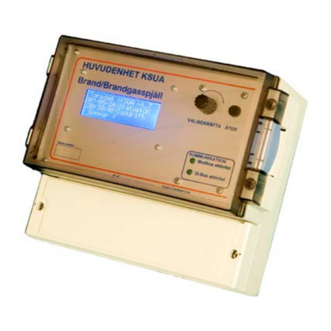
Abbildung exemplarisch! / exemplary picture!

1. Allgemein / In general
Seite / Page 2
1.1. Vorwort zu dieser Anleitung
Diese Anleitung ist für die fachgerechte Bedienung,
Installation und Wartung durch geschultes, sach-
kundiges Fachpersonal (wie z. B. Mechatroniker
oder Elektroinstallateur) und / oder Fachpersonal
mit Kenntnissen in der elektrischen Geräteinstalla-
tion ausgelegt.
Lesen Sie diese Betriebsanleitung aufmerksam
durch und halten Sie die vorgegebene Reihenfolge
ein. Bewahren Sie diese Betriebsanleitung für spä-
teren Gebrauch / Wartung auf. Bitte beachten Sie
genau die Anschlussbelegung, die minimalen und
maximalen Leistungsdaten (siehe „Technische Da-
ten”) und die Installationshinweise. Die unkorrekte
Verwendung oder nicht fachgerechte Bedienung /
Montage können den Verlust der Systemfunk-
tionen verursachen und Schäden an Sachen und /
oder Personen hervorrufen.
1.2. Produktbeschreibung
Die elektrische Steuereinrichtungen VENT 3/6 sind
Kompaktgeräte in einem Metallgehäuse. Sie ent-
halten Energieversorgung und die gesamte Steuer-
und Regelelektronik zum Betrieb von 24 V DC-An-
trieben. Die VENT 3/6 steuern die angeschlosse-
nen Antriebe zur täglichen Be- und Entlüftung.
Die VENT 3/6 können über die im Deckel integrier-
te Folientastatur bedient werden, zusätzlich ist es
möglich einen weiteren externen Lüftungstaster,
sowie mit Hilfe eines THM-200 (nicht im Lieferum-
fang enthalten) ein Thermostat mit anzuschließen.
Durch Anschluss eines Regen- bzw. Wind-/Regen-
Melders reagieren die VENT 3/6 selbsttätig auf un-
erwünschte Umwelteinflüsse.
Über die DIP-Schalter auf der Platine können fol-
gende Funktionen eingestellt werden:
• Dauerhafte Ansteuerung von
Öffneraggregaten nach Antippen des
Lüftungstasters,
• Totmannfunktion des Lüftungstasters,
• programmierbare Hubbegrenzung,
• Automatische Lüftung „ZU“
1.1. Foreword to this manual
This manual has been created for the purposes of
proper operation, installation and maintenance by
trained, experienced specialist personnel (e. g.
mechatronics or electrician) and /or specialist per-
sonnel with knowledge involving the installation of
electrical devices.
Read the operating manual carefully and follow the
prescribed sequence. Retain the operating manual
for later use /maintenance. Please precisely ob-
serve the pin assignment, the minimum and maxi-
mum performance data (see “Technical data”) and
the installation instructions. Incorrect usage or im-
proper operation /assembly can cause the loss of
system functions and result in damage to property
and /or persons.
1.2. Product description
The electric control panels VENT 3/6 are compact
devices in a metal housing. They contain power
supply and the total operating and control electron-
ics for the operation of 24 VDC-actuators. For the
daily ventilation the VENT 3/6 controls /triggers
the connected actuators.
The VENT 3/6 can be handled via the built-in cover
keypad, additionally it is possible to connect an oth-
er external vent switch, as well as a thermostat with
the support of a THM-200 (not included).
By connecting a rain or wind /rain detector, the
VENT 3/6 reacts independently to adverse environ-
mental influences,.
The following functions can be set via the DIP
switch on the board:
• continuous drive after tap on to the ventilation
button,
• dead man function of the ventilation button,
• adjustable stroke limitation,
• automatic ventilation CLOSED

GEFAHR
Die Montage darf nur von fach-
kundigem Personal (Elektrofach-
kraft nach DIN VDE 1000-10
bzw. BGV A3) durchgeführt wer-
den.
Bei nicht sachgemäßer Montage
besteht die Gefahr eines elektri-
schen Schlages. Halten Sie un-
bedingt die gültigen Sicherheits-
regeln ein.
Seite / Page 3
2. Montage / Mounting
2.1. Mechanischer Anschluss
Bohrlöcher anzeichnen. Position der Bohrlö-
cher, siehe Abbildung 1: „Befestigungspunkte
Gehäuse“.
Bohrlöcher erstellen.
Die VENT 3/6 mit vier, für den jeweiligen Un-
tergrund geeigneten Schrauben (Befesti-
gungsmittel sind nicht im Lieferumfang enthal-
ten) durch den Gehäuseboden befestigen.
2.1. Mechanical connection
Mark the positions of the drilling holes, see
Figure 1: “Fastening points housing”.
Make the drilling holes.
Fastening the VENT 3/6 with four, subsurface
suitable screws (fastenings are not included in
the scope of delivery) trough the housing bot-
tom.
Abbildung 1: Befestigungspunkte Gehäuse
Figure 1: Fastening points housing
DANGER
Mounting may be carried out only
by professional personnel (quali-
fied electrician)! All relevant na-
tional safety regulations and
rules apply to mounting, installa-
tion and commissioning.
If the installation is not carried out
correctly there is a danger of
electrocution. It is essential that
you adhere to the applicable
saodfjoasasojasj
safety regulations! Pay attention to the valid in-
stallation regulations. Incorrect installation can
lead to serious injuries.
VENT 6
VENT 3
fastening points
Befestigungspunkte
fastening points
Befestigungspunkte

2. Montage / Mounting
Seite / Page 4
2.2. Elektrischer Anschluss
GEFAHR
Trennen Sie die Anschlussleitung allpolig vom
Netz. Der Anschluss der VENT 3/6 darf nur
spannungsfrei erfolgen!
2.2.1. Peripherie-Geräte anschließen (24 V DC)
Anschlussleitungen der Peripherie-Geräte ein-
führen.
Leitungen gemäß Anschlussplan verbinden,
siehe Abbildung 4: „Anschlussplan“ auf
Seite 5.
Zugentlastung am Leitungskamm mittels Ka-
belbinder anbringen (siehe Abbildung 2: „Lei-
tungs-Sicherung“ auf Seite 5).
INFO
Dimensionierungshinweise Motorleitung (Faust-
formel):
Aderquerschnitt [mm²] =
einfache Leitungslänge [m]
x Motorenzahl
x Stromaufnahme pro Motor [A] / 73
Es gelten weiterhin die Vorschriften der DIN VDE
0100 und der DIN VDE 0298.
2.2.2. Anschluss 230 V AC
ACHTUNG
Installieren Sie, zur Wartungszwecken, einen all-
poligen Hauptschalter (N, L1) vor der VENT 3/6.
Anschlussleitungen einführen.
Leitungen gemäß Anschlussplan verbinden.
Zugentlastung am Leitungskamm mittels Ka-
belbinder anbringen (siehe Abbildung 2: „Lei-
tungs-Sicherung“ auf Seite 5).
INFORMATION
Dimension indications (rule of thumb):
Wire cross-section [mm²] =
wire length [m]
x number of motors
x power consumption per motor [A] / 73
The national regulations are valid.
2.2. Electrical connection
2.2.1. Connect peripheral devices (24 V DC)
Insert connecting cables of the peripheral de-
vices.
Connect wires according to wiring diagram,
see Figure 4: “Connection diagram” on
page 5.
Attach cord grip by fixing the cables with cable
ties at the cable comb (see Figure 2: “Cable fi-
xing” on page 5).
2.2.2. 230 V AC Connection
Insert the power supply cable.
Connect wires according to wiring diagram.
Attach cord grip by fixing the cables with cable
ties at the cable comb (see Figure 2: “Cable fi-
xing” on page 5).
DANGER
Disconnect the power supply cord for all poles
from the mains. The connection of the VENT 3/6
must be done volt-free!
ATTENTION
For maintenance purposes install an all-pole
mains switch (N, L1) before the VENT 3/6.

Seite / Page 5/6
2. Montage / Mounting
Abbildung 2: Leitungs-Sicherung
Figure 2: Cable fixing
Abbildung exemplarisch! / exemplary picture!
Abbildung 3: Anschluss THM 200 & Thermostat
Figure 3: THM 200 and thermostat connection
Abbildung 4: Anschlussplan
Figure 4: Connection diagram
Kabelbinder
cable ties
AZE
Lüftertaster
Vent switch
AZ
E
AZ
E
Lüftertaster
vent switch
LZE
–
Wind/Regen
Wind/Rain
521
WTS
43
THM 200
(nicht im Lieferumfang enthalten
not included in delivery)
AZ –
grün / green
blau / blue
schwarz / black
Thermostat
(2 Kanal / 2 channel)
weis / white
grau / grey
ϑ
VENT 3/6
NC
C
NO
AZE
Meldekontakt 2
Monitoring contact 2
Lüftertaster
Vent switch
Motor 2
LED OK
LED Störung / failure
L1
NPE
G OOSS
L1
NPE
AZ
E
AZ
E
OS
Lüftertaster
Motor 2
Netz-Anschluss –
allpolig trennender
Hauptschalter bauseits (L1, N)
MAINS –
pole disconnecting
main switch on site (L1, N)
vent switch
VENT 3: Maximale Stromaufnahme 3A £
VENT 3: Maximum current consumption 3A £
Motor 1
VENT 3: Motorkanal T3,15A
G OOSS
OS
Motor 1
VENT 3: Motor channel T3,15A
VENT 6: Motorkanal T6,3A
VENT 6: Motor channel T6,3A
VENT 6: Maximale Stromaufnahme 6A £
VENT 3: Maximum current consumption 6A £
LZE-
Wind/Regen
Wind/Rain
521
WTS / WS / GLT
WTS / WS / BMS
43
SW
1
EIN
ON
AUS
OFF
1
2
3
4
5
6
7
8
9
10
Anschlussleitung Folientastatur
Connection cable foil buttons
-------------------------------------------------------------------------------------------------------------------------------------------------------------------------

2. Montage / Mounting
Seite / Page 7
2.3. Deckel montieren
Verbinden Sie die PE-Leitung mit der PE-
Steckerfahne des Deckels.
-------------------------------------------------------------------
Verbinden Sie die Lüftungstaster-Anschluss-
leitung mit dem Stecker der Folientastatur.
Überprüfen Sie die Funktion der Folientaster
und drehen Sie den Stecker gegebenenfalls
um 180°.
-------------------------------------------------------------------
Setzen Sie den Führungsstift des Deckels auf
der linken Seite in die Bohrung der Gehäu-
seunterteils ein und befestigen Sie den Deckel
auf der rechten Seite mit zwei Schrauben.
Abbildung 5: PE-Anschluss
Figure 5: PE-Connection
Abbildung 6: Lüftungstaster
Figure 6: Vent switch
2.3. Mount cover
Connect the PE cable with the PE pin terminal
from the cover.
-------------------------------------------------------------------
Connect the vent switch connecting cable with
the plug of the keypad.
Check the function of the foil buttons and turn
the plug if necessary by 180°.
-------------------------------------------------------------------
Insert the guide pin of the cover on the left side
in the bore of the housing base and secure the
cover on the right side with two screws.
Abbildung 7: Deckel montieren
Figure 7: Mount cover
PE-Steckerfahne
PE pin terminal
Folientaster (Stecker)
Anschlussleitung VENT-3/6 (Buchse)
Connection cabel VENT-3/6 (socket)
Foil buttons (plug)
Befestigungs-
schrauben
fixing screws

3. Funktionen / Functions
Seite / Page 8
3.1. Lüftungsfunktionen
Zusätzlich zum integrierten Folientaster ist es mög-
lich einen externen Taster anzuschließen. Werden
beide Tasten (AUF / ZU) gleichzeitig betätigt, be-
wirkt das die Funktion STOPP.
Der Lüftungstaster kann mit unterschiedlichen Ak-
tionsverhalten belegt werden. Die Auswahlmög-
lichkeiten sind in der folgenden Tabelle dargestellt
und können mit dem Auswahl-Schalter SW1 auf
der VENT 3/6 Platine konfiguriert werden. Die
Richtungen werden jeweils über eine Betätigung
der Richtungstasten AUF / ZU (Signalzeit mehr als
500 ms) aktiviert .
3.1. Ventilation functions
In addition to the integrated foil buttons it is possible
to install an external button. Activating both buttons
(OPEN / CLOSED) simultaneously effectuates the
function STOP.
The switch can be allocated with various action be-
haviours. The options are displayed in the following
table and can be configured with the selector
switch SW1 on the VENT 3/6 board. The directions
are operated by using the directional switches
OPEN / CLOSED (signalling time more than
500 ms).
Abbildung 8: DIP Schalter SW1
Figure 8: DIP Switch SW1
SW 1

Seite / Page 9
3. Funktionen / Functions
Tabelle 1: Matrix Lüftertaster
Table 1: Matrix ventilation switch
Konfigu-
ration
Configur
ation
SW1
– 1
SW1
– 2
SW1
– 3
SW1
– 4
Belegung Lüftertaster
Configuration ventilation
switch
Bemerkung
Remarks
1 OFF OFF OFF OFF Dauer AUF / ZU
Continuous OPEN / CLOSED
Auslieferungszustand
Delivery state
2 ON OFF OFF OFF
AUF und ZU mit Totannfunk-
tion
OPEN and CLOSED with
dead man function Totmannfunktion – Antriebe fahren so
lange wie Taster gedrückt wird in AUF
oder ZU Richtung
Dead man function – the actuator will
run as long as the vent button is
pressed in OPEN or CLOSE.
3 OFF ON OFF OFF
AUF mit Totmannfunktion /
ZU ohne
OPEN with dead man
function / CLOSED without
4 ON ON OFF OFF
AUF ohne Totmannfunktion /
ZU mit
OPEN without dead man func-
tion / CLOSED with
5 OFF OFF ON OFF
Programmierte Hubbegren-
zung (Öffnungszeit)
Stroke limitation (opening
time)
Bei Ansteuerung über Lüftertaster
fährt die Anlage automatisch bis zur
Hubbegrenzung.
In case of ventilation the actuators
open for the programmed time.
6 ON OFF ON OFF
Automatische Lüftung ZU
Automatic ventilation CLOSED
Nach Ablauf der automatischen Lüf-
tungszeit „ZU“ schließt die Anlage
automatisch.
The system closes automatically after
the expiration of the time.
7 OFF ON ON OFF
Programmierbare Hubbegren-
zung mit Automatische Lüf-
tung ZU
Stroke limitation with auto-
matic ventilation CLOSED
Funktionskombination aus Konfigura-
tion 5 und 6.
Combination of configuration 5 and 6.
8 OFF OFF ON ON
Programmiermodus für Hub-
begrenzung
Programming mode for stroke
limitation
Siehe Kapitel 3.2.2. „Programmierab-
lauf Hubbegrenzung“ auf Seite 10.
See chapter 3.2.2. “Programming
sequence stroke limitation” on
page 10.
9 ON OFF ON ON
Programmiermodus für Auto-
matische Lüftung zu
Programming mode for auto-
matic ventilation closed
Siehe Kapitel 3.2.4. „Programmierab-
lauf Automatische Lüftung ZU“ auf
Seite 11.
See chapter 3.2.4. “Programming
sequence automatic ventilation CLO-
SED” on page 11.
10 ON ON ON ON Lüftertaster ausgeschaltet
Ventilation switch closed
Keine Lüftungsfunktion möglich.
Ventilation disabled.

ACHTUNG
Nur die aufgeführten Konfigurationen des DIP-
Schalters sind belegt. Bitte wählen Sie eine die-
ser Konfigurationen für Ihre Anwendung aus. Die
nicht aufgeführten Auswahl-Kombinationen des
DIP-Schalters sind nicht definiert und können zu
Fehlfunktionen führen.
3. Funktionen / Functions
Seite / Page 10
3.2.1. Hubbegrenzung (Öffnungszeit)
Konfiguration 5 oder 7 (siehe Tabelle 1: „Matrix
Lüftertaster“ auf Seite 9).
Die Hubbegrenzung wird durch Betätigen des Lüf-
tungstasters in AUF-Richtung aktiviert und ermög-
licht dem Benutzer die Antriebe automatisch eine
definierte Zeit aufzufahren. Die Funktion ist zeitge-
steuert und werkseitig auf 3 Sekunden eingestellt.
Die Hubbegrenzung (Zeit) kann vom Benutzer
nachträglich zwischen min. 3 Sekunden und max.
255 Sekunden verändert werden. Liegt die vom
Benutzer programmierte Zeit außerhalb dieses Be-
reiches, werden die Werkseinstellungen verwen-
det.
3.2.2. Programmierablauf Hubbegrenzung
Konfiguration 8 (siehe Tabelle 1: „Matrix Lüfter-
taster“ auf Seite 9).
Die Anlage muss vor Start der Programmierung fol-
genden Zustand aufweisen:
• Betriebszustand OK = Netzbetrieb;
• LED „Störung“ ist aus;
• RWA-Klappen geschlossen.
Konfiguration 8 (siehe Tabelle 1: „Matrix Lüf-
tertaster“ auf Seite 9) über DIP-Schalter SW1
wählen.
Der Programmiermodus wird über das
Leuchten der gelben LED angezeigt.
Start der Programmierung über die Tastenbe-
tätigung des Lüftertasters in Richtung AUF.
Haben die Klappen die gewünschte Position
(Laufzeit zwischen 3s und 255s möglich; werk-
seitig: 3s) erreicht, die Programmierung über
die Betätigung STOPP (AUF und ZU gleich-
zeitig) am Lüftertaster beenden.
3.2.1. Stroke limitation (opening time)
Configuration 5 or 7 (see Table 1: “Matrix ventila-
tion switch” on page 9).
The stroke limiting are activated by operating the
ventilator switch in OPEN direction and enables the
user to operate the actuator automatically for a de-
fined time. The function is time controlled and fac-
tory-set to 3 seconds.
The stroke limitation (time) can be modified after-
wards by the user between min. 3 seconds and
max. 255 seconds. The factory setting will be ap-
plied if the time set by user is outside this range.
3.2.2. Programming sequence stroke limitation
Configuration 8 (see Table 1: “Matrix ventilation
switch” on page 9).
Prior to the start of programming, the system must
display the following state:
• Operation state OK = mains operation;
• LED “Alarm” and LED “Fault” are off;
• Smoke vents are closed.
Configuration 8 (see Table 1: “Matrix ventila-
tion switch” on page 9) select DIP-switch SW1.
The programming mode is indicated by the
flashing of the yellow LED.
Start the programming mode by operating the
ventilator switch in OPEN direction.
Once the vents reach the desired position
(running time between 3 and 255 seconds are
possible; factory setting: 3 seconds), end the
programming by activating STOP (OPEN and
CLOSED simultaneously) at the ventilator
switch.
ATTENTION
Only the implemented DIP-switch configurations
are proven. Please select one of these configu-
rations for your application. The unimplemented
selection combinations of the DIP-switch are un-
defined and can lead to malfunctions.

Seite / Page 11
3. Funktionen / Functions
Durch Wahl einer Betriebskonfiguration (5
oder 7) am DIP-Schalter am SW1 wird der
Programmiermodus verlassen.
Das Ende des Programmiermodus wird
über das Erlöschen der gelben LED ange-
zeigt und der neue Öffnungshub (Zeit) dau-
erhaft gespeichert.
ACHTUNG
Bei der Hubbegrenzug ist die Totmannfunktion
in Richtung AUF inaktiv.
3.2.3. Automatische Lüftung ZU (zeitabhängig)
Konfiguration 6 oder 7 (siehe Tabelle 1: „Matrix
Lüftertaster“ auf Seite 9).
Ermöglicht dem Benutzer nach einer Lüftung das
automatische Schließen der Klappen. Die Lüf-
tungsfunktion ist zeitgesteuert und werksseitig auf
10 Minuten eingestellt.
Die Lüftungszeit kann vom Benutzer nachträglich
zwischen min. 10 Minuten und max. 18 Stunden
verändert werden. Liegt die vom Benutzer pro-
grammierte Zeit außerhalb dieses Bereiches, wer-
den die Werkseinstellungen verwendet.
3.2.4. Programmierablauf Automatische
Lüftung ZU
Die Anlage muss vor Start der Programmierung fol-
genden Zustand aufweisen:
• Betriebszustand OK = Netzbetrieb;
• LED „Störung“ ist aus;
• RWA-Klappen geschlossen.
-------------------------------------------------------------------
Konfiguration 9 (siehe Tabelle 1: „Matrix Lüfter-
taster“ auf Seite 9).
Der Programmiermodus wird über das
Leuchten der gelben LED angezeigt.
Start der Programmierung über die Tastenbe-
tätigung des Lüftertasters in Richtung AUF.
The programming mode is quit by selecting an
operation configuration (5 or 7) at the DIP-
switch SW1.
The end of the programming mode is indi-
cated by the disappearance of the yellow
LED and the new opening stroke (time) is
stored permanently
3.2.3. Automatic ventilation CLOSED (time-
dependent)
Configuration 6 or 7 (see Table 1: “Matrix ventila-
tion switch” on page 9).
Enables the user to close the vents automatically
after ventilation. The ventilation function is time
controlled and is factory-set to 10 minutes.
The ventilation time can be changed afterwards by
the user to min. 10 minutes and max. 18 hours. The
factory setting will be applied if the time set by user
is outside this range.
3.2.4. Programming sequence automatic
ventilation CLOSED
Prior to the start of programming, the system must
display the following state:
•Operation state OK = mains operation;
• LED “Fault” are off;
• smoke vents are closed.
-----------------------------------------------------------
Configuration 9 (see Table 1: “Matrix ventilation
switch” on page 9).
The programming mode is indicated by the
flashing of the yellow LED.
Start the programming mode by operating the
ventilator switch in OPEN direction.
ATTENTION
The dead man function in the OPEN direction is
inactive during stroke limitation.

3. Funktionen / Functions
Seite / Page 12
Waren die Klappen die gewünschte Zeit offen
(Lüftungszeit zwischen 10 Minuten und 18
Stunden; werksseitig: 10 Minuten), die Pro-
grammierung über die Betätigung ZU am
Lüftertaster beenden.
Durch Wahl einer Betriebskonfiguration (6
oder 7) am DIP-Schalter SW1 wird der Pro-
grammiermodus verlassen.
Das Ende des Programmiermodus wird
über das Erlöschen der gelben LED ange-
zeigt und die neue Spaltlüftungszeit dauer-
haft gespeichert.
3.2.5. Totmannfunktion
Konfiguration 2, 3 oder 4 (siehe Tabelle 1: „Matrix
Lüftertaster“ auf Seite 9).
Die Totmannfunktion ist eine Sicherheitsfunktion,
durch diese die Antriebe nur solange in die jeweili-
ge Richtung fahren, solange die jeweilige Rich-
tungstaste betätigt wird. Bei Loslassen des Tasters
stoppen die Antriebe sofort.
ACHTUNG
Bei Anschluss eines Wind- / Regenmelders an
die VENT 3/6 ist die Totmannfunktion deaktiviert
bzw. wird vom WTS übersteuert.
3.3. Wind / Regenmelder (WTS)
Der Wind- / Regenmelder ermöglicht dem Anwen-
der bei witterungsbedingten Einflüssen die zur Lüf-
tung geöffneten Klappen / Fenster automatisch zu
schließen. Nach Auslösen des Wind- / Regenmel-
ders wird ein permanenter ZU-Befehl erzeugt.
If the vents have been open for the desired
time (ventilation time between 10 minutes and
18 hours; factory setting: 10 minutes), end the
programming by activating CLOSED at the
ventilator switch.
The programming mode is quit by selecting an
operation configuration (6 or 7) at the DIP-
switch SW1.
The end of the programming mode is indi-
cated by disappearance of the yellow LED
and time is stored permanently.
3.2.5. Dead man function
Configuration 2, 3 or 4 (see Table 1: “Matrix ven-
tilation switch” on page 9).
The dead man function is a security function, allow-
ing the actuators to go in the respective direction as
long as the respective direction switch is operated.
The actuators immediately stop once the switch is
released.
3.3. Wind- / rain detector (WTS)
The wind- / rain detector allows the user to close
the for ventilation opened openings / windows,
caused by weather influences, automatically. A
permanent CLOSED command is generated after
the wind- / rain detector is triggered.
ATTENTION
The dead man function is deactivated and over
modulated by the WTS when a wind-/ rain detec-
tor is connected to the VENT 3/6.

Seite / Page 13
3. Funktionen / Functions
3.4. Externe Ausgabe von Meldungen
Für die Weiterleitung von Störmeldungen ist die
VENT 3/6 mit einem potentialfreien Relais bzw.
Kontakt ausgestattet. Die Zuordnung der Meldung
kann vom Benutzer über die DIP-Schalter 5 - 8 am
SW1 auf der VENT 3/6 Platine frei gewählt werden
(siehe Tabelle 2: „Matrix Melderelais (Contact 2)“).
3.4. External readout of messages
The VENT 3/6 is equipped with one volt-free relay
or contacts to redirect fault messages. The user
can select the allocation of the message using a
DIP-switch 5 -8 at SW1 on the VENT 3/6 board
(see Table 2: “Matrix signal relay (Contact 2)”).
Tabelle 2: Matrix Melderelais (Contact 2)
INFO
Die weiteren Schalterkombinationen ergeben
keine neuen Ausgabe-Möglichkeiten bzw. kön-
nen zu Fehlinformationen führen.
Table 2: Matrix signal relay (Contact 2)
3.5. Fehlermeldung
Die Anlage zeigt einen Fehler an (gelbe LED an),
wenn die Lastsicherung F2 (Motorkanäle) defekt
ist, bzw. wenn es zu einer Überlastung, einem
Kurzschluss an den Motorausgängen kommt.
3.5. Error message
The system displays an error (yellow LED on) when
the load fuse F2 (motor channels) is defective, or if
there is a short circuit or an overload across the
motor terminals.
SW1
– 5
SW1
– 6
SW1
– 7
SW1
– 8
Belegung Contact2
Allocation contact 2
Bemerkung
Remarks
OFF OFF OFF OFF OK Auslieferungszustand
Delivery state
ON OFF OFF OFF Antriebe in Richtung AUF angesteuert
Actuators triggered in OPENING-direction
OFF ON OFF OFF Antriebe in Richtung ZU angesteuert
Actuators triggered in CLOSING-direction
ON ON OFF OFF Wind / Regenmelder „ZU aktiv“
Wind- /rain detector “CLOSING active”
INFORMATION
The other switch combinations found no new
output options and can lead to misinformation.

4. Technische Daten/ Technical data
Seite / Page 14
4.1. Netzanschlussdaten
4.1. Power supply information
4.2. Ausgang Motorkanäle
4.2. Output information motor channels
4.3. Anschlussdaten Wind-, Regenmelder
(WTS)
4.3. Connection information wind-, rain-
detector (WTS)
4.4. Anschlussdaten Lüftertaster
4.4. Connection information ventilation
switch
Nennspannung:
Nominal voltage: 230 V AC
Zulässiger Spannungsbereich:
Acceptable voltage range: 195 V bis / to 264 V
Stromaufnahme1:
Current consumption2:
1. Stromaufnahme bei maximaler Last des Versorgungssystems.
2. Power consumption during maximum load of the supply system.
0,56 A (VENT 3)1
1,2 A (VENT 6)
0.56 A (VENT 3)2
1.2 A (VENT 6)
min. Vorsicherung (bauseitig):
Min. series fuse (on side): C 16 A
Anschlussleistung:
Connected load:
103 VA (VENT 3)
206 VA (VENT 6)
Einschaltstromstoß:
Inrush current:
ca. 10 A (VENT 3)
ca. 20 A (VENT 6)
Frequenzbereich:
Frequency range: 47 Hz bis / to 63 Hz
Netzabsicherung (intern):
Main fuse (internal):
Typ T 1,25 A
Type T 1.25 A
Netzanschlussleiterquerschnitt:
Power supply line cross section:
mindestens 1,5 mm²
at least 1.5 mm²
Klemmenausführung:
Clamp format:
0,5 mm² – 2,5 mm²
0.5 mm² – 2.5 mm²
Einschaltdauer (ED):
Duty cycle (D): 30%
AusgangsspannungNetzbetrieb
(nominal):
Output voltage mains operation
(nominal):
24 V DC
Zulässiger Spannungsbereich:
Acceptable voltage range:
23,0 V DC bis
24,5 V DC
23.0 V DC to
24.5 V DC
Ausgangsstrom (Iout)
(Kurzzeitbetrieb)
(Iout = Imot1 + Imot2):
Output Current (Iout)
(short-term operation)
(Iout = Imot1 + Imot2):
3 A (VENT 3)
6 A (VENT 6)
Ausgangsleistung (Dauerbe-
trieb):
Power output (non-stop opera-
tion):
50 W (VENT 3)
100 W (VENT 6)
Ausgangsleistung (Kurzzeitbe-
trieb):
Power output (short-term opera-
tion):
73,5 W (VENT 3)
147 W (VENT 6)
Ausgangssicherung für
Antriebe:
Output fuse for actuators:
Typ T 3,15 A (VENT 3)
Typ T 6,3 A (VENT 6)
Type T 3.15 A (VENT 3)
Type T 6.3 A (VENT 6)
Ripple der Ausgangsspannung
(0 A < Iout < 3 A) Vpp:
Ripple of the output voltage
(0 A < Iout < 3 A) Vpp:
300 mV
Klemmenausführung:
Clamp format:
0,5 mm² – 2,5 mm²
0.5 mm² – 2.5 mm²
Maximale Anzahl
Maximum number: 1
Ausgangsspannung (E):
Output voltage range (E):
Klemme 9
Clamp 9
23,0 V DC bis
24,5 V DC
23.0 V DC to
24.5 V DC
Strombelastbarkeit (E):
Current carrying capacity
(E):
Klemme 9
Clamp 9 max. 150 mA
Eingangsspannungsbere-
ich (LZ):
Input voltage range (LZ):
Klemme 10
Clamp 10
15 V DC bis / to
30 V DC
Ausgangsspannungsbe-
reich (E)
Output voltage range
(E):
Klemme 22
Clamp 22
23,0 V DC bis
24,5 V DC
23.0 V DC to
24.5 V DC
Strombelastbarkeit (E)
Current carrying capac-
ity (E):
Klemme 22
Clamp 22 max. 15 mA
Eingangsspannungsbe-
reich (A)
Input voltage range (A):
Klemme 24
Clamp 24
15 V DC bis / to
30 V DC
Eingangsspannungsbe-
reich (Z)
Input voltage range (Z):
Klemme 23
Clamp 23
15 V DC bis / to
30 V DC

Seite / Page 15
4. Technische Daten/ Technical data
4.5. Anschlussdaten potenzialfreier
Kontakt 2 „NO / C / NC“
4.5. Connection information volt free
contact 2 “NO / C / NC”
4.6. Mechanische Eigenschaften
4.6. Mechanical features
4.7. Anschluss und Betrieb
4.7. Connection and operation
4.8. Einbau- und
Umgebungsbedingungen
4.8. Installation and environmental
requirements
Spannungsbelastbarkeit
des Schaltkontaktes 2
(C - NO):
Voltage capacity of
switching contact 2
(C - NO):
Klemme 35
auf Klemme
34
Clamp 35 on
clamp 34
max. 30 V DC
Spannungsbelastbarkeit
des Schaltkontaktes 2
(C - NC):
Voltage capacity of
switching contact 2
(C - NC):
Klemme 35
auf Klemme
36
Clamp 35 on
clamp 36
max. 30 V DC
Strombelastbarkeit des Schaltkontak-
tes 2 (C - NO bzw. C - NC) – Ohmsche
Last:
Voltage capacity of switching contact 2
(C - NO resp. C - NC) – ohmic load:
max. 2 A DC
Schaltleistung:
Switching power:
60 W / 62,5 VA
60 W / 62.5 VA
Maße VENT 3 (B x H x T):
Size VENT 3 (w x h x d): 301 x 323 x 85 mm
Maße VENT 6 (B x H x T):
Size VENT 6 (w x h x d): 301 x 444 x 85 mm
Gewicht:
Weight:
4,10 kg (VENT 3)
6,30 kg (VENT 6)
4.10 kg (VENT 3)
6.30 kg (VENT 6)
Schutzart:
Protection type:
IP20 nach EN 60 529
IP20 acc. EN 60 529
Gehäuse:
Housing:
Stahl
(pulverbeschichtet)
Steal (powder coated)
Farbe:
Colour: RAL 9010
Schutzklasse:
Protection class: I
Anschluss:
Connection:
Siehe Abbildung 4:
„Anschlussplan“ auf
Seite 5.
See chapter Figure 4:
“Connection diagram”
on page 5.
Anschlussklemmen:
Terminal clamps:
Zugfederklemmen
0,5 mm² – 2,5 mm²
Tension spring clamp
0.5 mm² – 2.5 mm²
Abschaltung der Antriebe in
jeder Position:
Switching off the actuators in
any position:
Ja
Yes
Maximale Leitungslänge zwi-
schen Steuereinheit und
Antrieb:
Maximum wire length between
control unit and actuator:
Siehe Kapitel 2.2.
„Elektrischer
Anschluss“ auf Seite 4.
See chapter 2.2. “Elec-
trical connection” on
page 4.
Öffnungs- / Schließvorgang:
Opening- / closing process:
Umpolung der Betriebs-
spannung
Pole reversal of the
operating voltage.
Pausenzeit bei Fahrtrichtungs-
änderung:
Pause time during direction
change:
200 ms
Wartung:
Maintenance:
Wartungsfrei
Maintenance free
Betriebstemperatur:
Operating temperature -5 bis / to 40 °C
Lagertemperatur:
Storage temperature -5 bis / to 40 °C
Geeignet für Außenmontage:
Suitable for outdoor installation:
Nein
No

5. Anhang / Appendix
Seite / Page 16
5.1. Gewährleistungsbedingungen
Siehe Beiblatt „Sicherheitshinweise und Garantie-
bedingungen“.
5.1. Warranty conditions
See attached sheet “safety instructions and terms
of guarantee”.
5.2. Allgemeine Geschäfts- und
Lieferbedingungen
Siehe Beiblatt „Sicherheitshinweise und Garantie-
bedingungen“.
5.2. General conditions of buisiness and
terms of delivery
See attached sheet “safety instructions and terms
of guarantee”.
5.3. EG-Herstellererklärung
Hiermit erklären wir die Konformität
des Produktes mit den dafür geltenden
Richtlinien. Die Konformitätserklärung
kann in der Firma eingesehen werden und wird
Ihnen auf Anforderung zugesandt. Diese Erklä-
rung bescheinigt die Übereinstimmung mit den
genannten Richtlinien, beinhaltet jedoch keine
Zusicherung von Eigenschaften. Bei einer nicht
mit uns abgestimmten Änderung verliert diese
Erklärung ihre Gültigkeit.
5.3. EC Manufacturer’s declaration
We hereby declare the conformity of
the product with the applicable guide-
lines. The declaration of conformity
can be viewed in the company and will be deliv-
ered upon request. This declaration certifies con-
formity with the directives mentioned, but gives no
guarantee of characteristics. This declaration
becomes invalid following a change that has been
made without our consent.
5.4. EG-Herstellererklärung
(Inverkehrbringer)
Siehe Beiblatt „Sicherheitshinweise und Garantie-
bedingungen“.
5.4. EC Manufacturer’s declaration
(distributor)
See attached sheet “safety instructions and terms
of guarantee”.
5.5. Firmenanschriften / Company
addresses
5.5.1 Deutschland / Germany
Simon RWA®Systeme GmbH
Medienstraße 8
D ದ94036 Passau
Tel.: +49 (0)851 98870 -0
Fax: +49 (0)851 98870 -70
Internet: www.simon-rwa.de
5.5.2 Schweiz / Switzerland
Simon RWA®Systeme AG
Allmendstrasse 8
CH ದ8320 Fehraltorf
Tel.: +41 (0)44 956 50 30
Fax: +41 (0)44 956 50 40
Internet: www.simon-rwa.ch
5.5.3 Ungarn / Hungary
Simon RWA®Rendszer Kft.
Sodras utca 1. fszt. 1
H ದ1026 Budapest
Tel.: +36 (0)30 552 0424
E-Mail: [email protected]
This manual suits for next models
1
Table of contents
Other SIMON RWA Control Panel manuals
Popular Control Panel manuals by other brands
BFT
BFT ALTAIR-P Installation and user manual
Aquamatic
Aquamatic TAC-3000 quick start guide
ETNA
ETNA Hydropan Operation and maintenance manual
Beckhoff
Beckhoff CP79 Series Installation and operating instructions
Danfoss
Danfoss VLT LCP 21 installation instructions
ETI
ETI Snow Switch PD PRO QUICK REFERENCE INSTALLATION MANUAL
