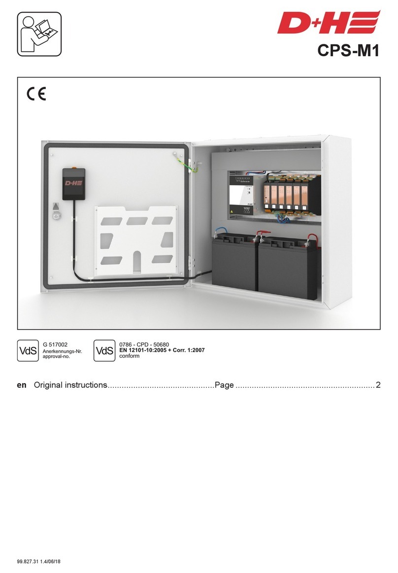
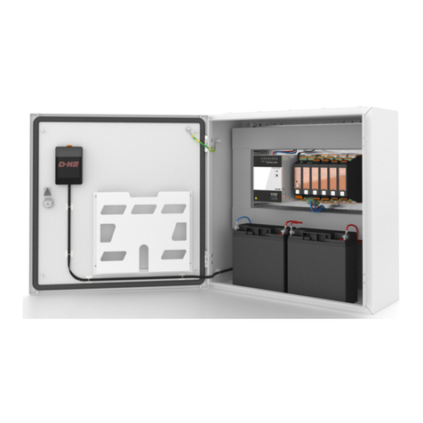
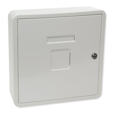
D+H ZP GVL 8408-M User manual

GVL 8408-M
99.823.56 1.2/11/15
de Originalbetriebsanleitung . . . . . . . . . . . . . . . . . . . Seite . . . . . . . 3
en Original instructions . . . . . . . . . . . . . . . . . . . . . . . Page . . . . . . . 9
GVL 8408-M
(ZP GVL 8408-M + GEH-KST)

GVL 8408-M GVL 8408-M
99.823.56 1.2/11/1599.823.56 1.2/11/15
2/16 3/16
S1
F3.15A
T1,25A
S2
F3.15A
S3
F3.15A
S4
F3.15A
S5
F6.3A
Power
230 VAC
www.dh-partner.com
Lüftungszentrale
GVL 8408-M
Group 1 Group 2 Group 3 Group 4 Group 5
Sicherung
Gruppe 1
DIP-Schalter S1
Steckleiste für
GME 83 Gruppenmodul
Sicherung
Gruppe 2
DIP-Schalter S2
Sicherung
Gruppe 3
DIP-Schalter S3
Sicherung
Gruppe 4
DIP-Schalter S4
Sicherung
Gruppe 5
DIP-Schalter S5
Netzanschluss Sicherung Netz LED Netz
- Lüftungssteuerung für kleine bis mittlere
Bauobjekte
- Zur Ansteuerung von 24 VDC Antrieben
- 5 Lüftungsgruppen, auf 6 Gruppen erweiterbar
- 8 A Antriebstrom - stabilisiert
- Erweiterbar mit D+H Zubehör
- Nur für die Innenmontage geeignet
Inhaltsverzeichnis
Leistungsmerkmale
- Lüftungs-Sicherheitsfunktion (Speicherbetrieb
Auf/Zu), frei codierbar
- Wetterautomatik für einzelne Gruppen
ein-/ausschaltbar
- Eingang für externe Steuerung, z.B. Zeitschaltuhr
- Anschluss von Regenmelder bzw. Wind-
Regenmelder ohne Zusatzmodul möglich
- Kunststoffgehäuse mit abschließbarer
Stahlblechtür
Betriebsspannung 230 VAC!
Verletzungsgefahr durch Stromschlag!
- Anschluss darf nur durch eine autorisierte
Elektrofachkraft erfolgen
- Nur für die Innenmontage geeignet.
- Nur unveränderte D+H-Originalteile verwenden
Sicherheitshinweise
Anwendungsbeispiel
Gruppen
Fensterantriebe*
Lüftungstaster* Raumtemp.-Regler* Lüftungszentrale (GVL 8408-M) Regenmelder*
Fremdansteuerung*
* optionale Funktionserweiterung
(Separate Komponenten, nachrüstbar!)/
Diese Anleitung enthält Beschreibungen und
Anschlusspläne von Komponenten, die im
Lieferumfang der Zentrale nicht enthalten sind.
Diese, und viele weitere Teile, können Sie separat
bei Ihrem D+H-Partner erhalten. Weitere
Anschlusspläne sind dort ebenfalls erhältlich.
GME 83
GME 83
Gruppenmodul-Einschub*
Ansicht Grundplatine
Deutsch Deutsch
Bestimmungsgemäße Verwendung
Bestimmungsgemäße Verwendung .......................2
Sicherheitshinweise ...............................................2
Leistungsmerkmale / Garantie................................2
Wartung und Reinigung / Entsorgung......................2
Konformitätserklärung............................................2
Anwendungsbeispiel ..............................................3
Ansicht Grundplatine ..............................................3
Einbau....................................................................4
Technische Daten...................................................4
Kodierung der Gruppen ..........................................5
Kabelverlegeplan ...................................................5
230 VAC Versorgung ..............................................6
Anschluss ..........................................................6 - 7
Bedienung..............................................................8
Gruppeneinschub GME 83 .....................................8
Konformitätserklärung
Wir erklären in alleiniger Verantwortung, dass das
unter „Technische Daten“ beschriebene Produkt mit
den folgenden Richtlinien übereinstimmt:
2014/30/1EU, 2014/35/EU
Technische Unterlagen bei:
D+H Mechatronic AG, D-22949 Ammersbek
Dirk Dingfelder Maik Schmees
Vorstand Prokurist, Technischer Leiter
17.11.2015
Wartung und Reinigung
Die Inspektion und Wartung hat gemäß den D+H-
Wartungshinweisen zu erfolgen. Es dürfen nur
original D+H-Ersatzteile verwendet werden. Eine
Instandsetzung erfolgt ausschließlich durch D+H.
Wischen Sie Verschmutzungen mit einem trock-
enen, weichen Tuch ab.
Verwenden Sie keine Reinigungs- oder Lösemittel.
Garantie
Auf alle D+H-Artikel erhalten Sie 2 Jahre Garantie ab
belegter Übergabe der Anlage bis max. 3 Jahre nach
Auslieferungsdatum, wenn die Montage bzw.
Inbetriebnahme durch einen von D+H autorisierten
Service- und Vertriebspartner durchgeführt wurde.
Bei Anschluss von D+H-Komponenten an
Fremdanlagen oder Vermischung von D+H-
Produkten mit Teilen anderer Hersteller erlischt die
D+H-Garantie.
Elektrogeräte, Zubehör, Batterien und Verpackungen
sollen einer umweltgerechten Wiederverwertung
zugeführt werden. Werfen Sie Elektrogeräte und
Batterien nicht in den Hausmüll!
Nur für EU-Länder:
Gemäß der Europäischen Richtlinie 2012/19/EU
über Elektro- und Elektronik-Altgeräte und ihrer
Umsetzung in nationales Recht müssen nicht mehr
gebrauchsfähige Elektrogeräte getrennt gesammelt
und einer umweltgerechten Wiederverwertung
zugeführt werden.
Entsorgung

GVL 8408-M GVL 8408-M
99.823.56 1.2/11/1599.823.56 1.2/11/15
4/16 5/16
Typ GVL 8408-M
Nennspannung 230 VAC, 50 Hz
Nennleistung 240 VA
Stand-by Leistung 2,5 W
Bertriebsart Kurzzeit, 20%
Schutzklasse I
Schutzart IP 30
Temp. Bereich -5...+40°C
Ausgangsspannung 24 VDC
Restwelligkeit <10%
Ausgangsstrom: *
Laufstrom der Antriebe 6,4 A
Nennstrom der Antriebe 8 A
Gehäuse Kunststoff, Stahlblechtür
Farbe weiss
Abmessungen 310 x 310 x 100 mm
* Bitte beachten:
Der Ausgangsstrom der Gruppen 1 ... 4
beträgt max. 4 A (Gruppe 5 max. 8 A).
Der Gesamtstrom der Zentrale von max. 8 A
darf dabei nicht überschritten werden.
01
02
03
04
05
06
07
08
09
10
11
12
13
14
01
02
03
04
05
06
07
08
09
10
11
12
13
14
A B C
ZP GVL 8408-M
2 x 1,2 Ah
2 x 3,4 Ah
Ø max. 5 mm
(nicht enthalten)
4x
Zentrale geschützt und in Antriebsnähe montieren.
Eine detailierte Montageanleitung liegt dem Gehäuse bei.
Einbau Lüftungszentrale mit Gehäuse GEH-KST
GEH-KST
Kabelverlegeplan (Muster)
230 VAC, 50 Hz
zu weiteren
siehe Kabellängen und Querschnitte
Fensterantrieb Zentrale
Lüftungstaster
ca. 1,2 über OKFF
Fremdan-
steuerung
4x 0,8 Ø
4x 0,8 Ø
2x 0,8 Ø
4x 0,8 Ø
Regenmelder Raumtemperatur-
regler
Kabellängen und Querschnitte
Kodierung der Gruppen – DIP-Schalter S1 ... S5
Mit den DIP-Schaltern S1 ... S5 auf der Zentralengrundplatine und, falls vorhanden, auf dem
Gruppeneinschub lassen sich folgende Funktionen für jede Gruppe separat einstellen.
Der Auslieferzustand der DIP-Schalter ist OFF.
1 = ON Die Antriebe fahren durch einmaliges Drücken auf den Lüftungstaster* ZU.
1 = OFF Die Antriebe fahren nur solange ZU, wie der Lüftungstaster* gedrückt wird.
2 = ON Die Antriebe fahren durch einmaliges Drücken auf den Lüftungstaster* AUF.
2 = OFF Die Antriebe fahren nur solange AUF, wie der Lüftungstaster* gedrückt wird.
3 = ON Die Antriebe fahren bei Auslösen der „Zentral-ZU" Funktion, z.B. durch Regenmelder
oder Raumtemperaturregler, automatisch ZU.
3 = OFF Die Antriebe fahren nur durch Drücken des jeweiligen Lüftungstasters* ZU.
4 = ON Die Antriebe fahren bei Auslösen der „Zentral-AUF" Funktion, z.B. durch
Raumtemperaturregler, automatisch AUF.
4 = OFF Die Antriebe fahren nur durch Drücken des jeweiligen Lüftungstasters* AUF.
* Der Lüftungstaster der jeweiligen Gruppe
Akkuhalter
Technische DatenPosition der Zentralplatine
Gesamtstrom
0,5
240
400
640
1
120
200
320
1,5
80
130
213
2
60
100
160
2,5
48
80
128
3
40
65
107
3,5
34
55
91
4
30
50
80
4,5
27
44
71
5
24
40
64
5,5
22
36
58
6
20
33
53
6,5
18
31
49
7
17
28
46
7,5
16
27
43
8
15
25
40
m
m
m
Typ
2x 1,5 mm²
2x 2,5 mm²
2x 4 mm²
Querschnitt (mm²) = Kabellänge (m) x Gesamtstrom
80
Systemspannung 24 VDC! Leitungen nicht mit
Starkstromleitungen zusammen verlegen!
Bei einer Leitung mit Schutzleiter (grün/ gelb)
darf dieser nicht verwendet werden!
Deutsch Deutsch
CENTRALA ZAMKNIĘĆ
OGNIOWYCH
CONTRÔLE DE PORTES
COUPE-FEU
FIRE DOOR CONTROL
BRANDABSCHLUSS
תוררואתה
ΑΕΡΙΣΜΌΣ
ﺔﯾوﮭﺗ
HAVALANDIRMA
VENTILĀCIJA
VENTILASJON
TUULETUS
LTVENTILIACIJA
VENTILAZIONE
VENTILATSIOON
VĚTRÁNÍ
VETRANIE
SZELLŐZÉS
VENTILATIE
WENTYLACJA
VENTILATION

GVL 8408-M GVL 8408-M
6/16 7/16
Anschluss – Lüftungstaster und Fensterantriebe
Leitungslängen
und Querschnitte
siehe Seite 5
4 5 6 7
GVL 8408-M
–
Mot.b
Mot.a
X
A
Z
L (Aufmeldung, nur LT 43U-SD)
LT MOT
1 2 3
Lüftungstaster
(z.B. LT 84-U-SD)
LP
Mot.b
Mot.a
24 VDC
Fensterantriebe
Mot.b
Mot.a
4
GVL 8408-M
+G
Az
Zz
–
X1
123
Fremdansteuerung
für zentrales Schließen
(z.B. Zeitschaltuhr)
Antriebsgruppe 1 ... 5 (6)
Fragen Sie Ihren D+H-Partner für weitere Anschlussbilder.
230 VAC Versorgung
L
N
PE
230 VAC, 50 Hz
Anschluss – Regenmelder und Raumtemperaturregler
* Ader direkt anschließen, wenn kein Automatik-Schalter vorhanden. Die manuelle Bedienung ist dann außer Funktion.
< optional >
–
+
124357689
WRG 82
S 1/1
S 1/2
P3 P4
+G
–
Zz
Az
1 2 3 4
GVL 8408-M
VRS 10
–
–
+24V
21 3 4 5 6
Brücke
einsetzen!
Brücke einsetzen!
Mot.b
Mot.a
24 VDC
Fenster-
antrieb
L
–
Z
A
X
Mot.a
Mot.b
1234567
GVL 8408-M
LT MOT
LT 84-U +
LT 84-U-W
PPS
–
51
3
2
RTR 231
+G
–
Zz
Az
1 2 3 4
GVL 8408-M
VRS 10
–
–
+24V
21 3 4 5 6
Mot.b
Mot.a
24 VDC
Fenster-
antrieb
L
–
Z
A
X
Mot.a
Mot.b
1234567
GVL 8408-M
LT MOT
LT 84-U +
LT 84-U-W
PPS
Schutzkappe:
Die beiliegende Schutzkappe
nach Anschluss des Netzkabels
über die Netzklemme stecken.
Deutsch Deutsch
99.823.56 1.2/11/1599.823.56 1.2/11/15
X1
X1

ST OP ST OP ST OP
Bedienung - Tägliche Lüftung
Öffnen: Schliessen: Stoppen:
Lüftungstaster benötigt
STOP
Nur wenn Wind- oder Regenmelder vorhanden:
Wenn die Wetterautomatik über den Lüftungstaster LT 84-U-W
(optional) eingeschaltet ist, läuft die Anlage bei Wind oder Regen zu.
Sie läuft nach Wind- oder Regenende nicht automatisch wieder auf.
Öffnung der Anlage zum Lüften über den Lüftungstaster.
Soll bei schlechtem Wetter Spaltlüftung betrieben werden, so kann die
Wetterautomatik am LT 84-U-W (optional) abgeschaltet werden. Ist
kein LT 84-U-W vorhanden, ist Spaltlüftungsbetrieb bei schlechtem
Wetter nicht möglich.
Bedienung - Wetterautomatik
- Mit dem GME 83 kann die Zentrale um eine weitere
Antriebsgruppe ergänzt werden.
- Der Ausgangsstrom darf maximal 3 A betragen.
- Der Einschub kann, wie die fest installierten Gruppen auf der
Grundplatine der Zentrale, mit einem DIP-Schalter kodiert werden
(siehe Seite 5).
- Der GME 83 wird auf die Steckleiste M1 gesteckt.
- Der Anschluss entspricht dem der Standardgruppen.
Gruppeneinschub GME 83 (Zubehör)
GME 83
F3,15A
GVL 8408-M GVL 8408-M
8/16 9/16
EnglishDeutsch
Table of contents
Performance features
- Ventilation safety function (key operation
OPEN/CLOSE), can be free encoded
- Weather automatic for single groups,
can be switched on and off
- Entry for external control, e.g. timer
- Possibility of connecting rain detector or wind/ rain
detector without supplementary module
- Plastic housing, surface mounted type with
lockable steel sheet door
Intended use
- Ventilation control for small to medium sized
building objects
- For triggering of 24 VDC drives
- 5 ventilation groups, expandable to 6 groups
- 8 A total actuating current - stabilized
- Expandable with D+H accessories
- Only for indoor mounting
Safety notes
Operating voltage 230 VAC!
Risk of injury from electric shock!
- Connection has to be carried out only by an
authorized electrical specialist
- Only for inside mounting
- Just use unchanged original D+H parts
Intended use...........................................................9
Safety notes............................................................9
Performance features / Guarantee..........................9
Maintenance and cleaning / Disposal......................9
Declaration of Conformity .......................................9
Assembly scheme ................................................10
View motherboard ................................................10
Mounting...............................................................11
Technical Data ......................................................11
Encoding of groups...............................................12
Wiring plan............................................................12
230 VAC supply ....................................................13
Connection.....................................................13 - 14
Operation .............................................................15
Group plug-in unit GME 83....................................15
99.823.56 1.2/11/1599.823.56 1.2/11/15
Automatic
on/off
LT 84-U-W
Electrical devices, accessories, batteries and packa-
ging should be sorted for environmental-friendly
recycling. Do not dispose electrical devices and
batteries into household waste!
Only for EC countries:
According the European Guideline 2012/19/EU for
waste electrical and electronic equipment and its
implementation into national right, electrcal devices
that are no longer usable must be collected separa-
tely and disposed of in an environmentally correct
manner.
DisposalDeclaration of Conformity
We declare under our sole responsibility that the
product described under “Technical Data” is in
conformity with the following directives:
2014/30/EU, 2014/35/EU
Technical file at:
D+H Mechatronic AG, D-22949 Ammersbek
Dirk Dingfelder Maik Schmees
Member of the Board Authorized signatory, Technical Director
17.11.2015
Maintenance and cleaning
Inspection and maintenance has to be carried out
according to D+H maintenance notes. Only original
D+H spare parts may be used. Repair is to be carried
out exclusively by D+H.
Wipe away debris or contamination with a dry, soft
cloth.
Do not use cleaning agents or solvents.
Guarantee
You will get 2 years guarantee for all D+H products
from date of verified handing over of the system up to
maximal 3 years after date of delivery, when
mounting and starting has been carried out by an
authorized D+H-distributor.
D+H guarantee is expired, with connection of D+H
components with external systems or with mixing of
D+H products with parts of other manufacturers.

Type GVL 8408-M
Nominal voltage 230 VAC, 50 Hz
Rated power 240 VA
Stand-by operating 2,5 W
Class of rating short-time duty, 20%
Protection class I
Ingress protection IP 30
Temperature range -5...+40°C
Output voltage 24 VDC
Res. ripple <10%
Safe output: *
Running current of drives 6,4 A
Rated current of drives 8 A
Housing plastic, steel sheet door
Colour white
Dimensions 310 x 310 x 100 mm
* Please observe:
The output current of the groups 1 ... 4
amounts max. 4 (Group 5 max. 8 A).
The total output current of the control
panel, is limited up to 8 A.
Technical Data
GVL 8408-M GVL 8408-M
10/16 11/16
English
English
S1
F3.15A
T1,25A
S2
F3.15A
S3
F3.15A
S4
F3.15A
S5
F6.3A
Power
230 VAC
www.dh-partner.com
Ventilation Control Panel
GVL 8408-M
Group 1 Group 2 Group 3 Group 4 Group 5
fuse
group 1
DIP-switch S1
Mulitpoint connector for
GME 83 group plug-in unit
fuse
group 2
DIP-switch S2
fuse
group 3
DIP-switch S3
fuse
group 4
DIP-switch S4
fuse
group 5
DIP-switch S5
mains supply fuse mains LED mains
View motherboard
01
02
03
04
05
06
07
08
09
10
11
12
13
14
01
02
03
04
05
06
07
08
09
10
11
12
13
14
A B C
ZP GVL 8408-M
2 x 1,2 Ah
2 x 3,4 Ah
Ø max. 5 mm
(not included)
4x
Mount control panel sheltered and in proximity of drive.
Detailed installation instructions are supplied with the housing.
Mounting of ventilation control panel with housing GEH-KST
GEH-KST
battery holder
Position of the central pcb
Assembly scheme
groups
window drives*
vent button* room temp. control* control panel (GVL 8408-M) rain detector*
external control*
GME 83
GME 83
group module-plug-in unit*
* optional function extension
(separate components, retrofitable!)
This instruction includes descriptions and
connection plans of components which are not part
of scope of supply of control panel. You can order
these parts and many more separately from your
D+H distributor. Further connecting plans are
available there as well.
99.823.56 1.2/11/1599.823.56 1.2/11/15
CENTRALA ZAMKNIĘĆ
OGNIOWYCH
CONTRÔLE DE PORTES
COUPE-FEU
FIRE
DOOR
CONTROL
BRANDABSCHLUSS
תוררואתה
ΑΕΡΙΣΜΌΣ
ﺔﯾوﮭﺗ
HAVALANDIRMA
VENTILĀCIJA
VENTILASJON
TUULETUS
LT VENTILIACIJA
VENTILAZIONE
VENTILATSIOON
VĚTRÁNÍ
VETRANIE
SZELLŐZÉS
VENTILATIE
WENTYLACJA
VENTILATION

Encoding of groups – DIP-Switch S1 ... S5
Following functions can be adjusted for each group separately with DIP switch S1 - S5 on motherboard
of control panel and on group plug-in unit, if available.
The delivery state of all DIP-switches is OFF.
1 = ON Drives CLOSE up to final position by single pressing on respective vent button.
1 = OFF Drives are closing only so long as the vent button is pressed.
2 = ON Drives OPEN up to final position by single pressing on vent button.
2 = OFF Drives are opening only so long as the vent button is pressed.
3 = ON Drives are automatically closed by trigger of function „Central CLOSE",
e.g. by rain detector or room temperature control.
3 = OFF Drives can be closed only by pressing the respective vent button.
4 = ON Drives are automatically opened by trigger of function „Central OPEN",
e.g. by room temperature control.
4 = OFF Drives can be opened only by pressing the respective vent button.
* The vent button of the respective group.
Wiring plan (Paragon)
230 VAC, 50 Hz
to further ones
see line lenghts and cross sections
window drive control panel
vent button
ca. 1,2 m above
upper edge
firm flooring
external
control
4x 0,8 Ø
4x 0,8 Ø
2x 0,8 Ø
4x 0,8 Ø
rain sensor room temperature
control
Line lenghts and cross sections
Output voltage 24 VDC!
Do not run cables together with power lines!
In case of a cable with ground wire
(e.g. green / yellow) this must not be used!
total current
0,5
240
400
640
1
120
200
320
1,5
80
130
213
2
60
100
160
2,5
48
80
128
3
40
65
107
3,5
34
55
91
4
30
50
80
4,5
27
44
71
5
24
40
64
5,5
22
36
58
6
20
33
53
6,5
18
31
49
7
17
28
46
7,5
16
27
43
8
15
25
40
m
m
m
type
2x 1,5 mm²
2x 2,5 mm²
2x 4 mm²
Connection – Vent buttons and Window drives
Line lengths and
cross sections
see page 12
4 5 6 7
GVL 8408-M
–
Mot.b
Mot.a
X
A
Z
L (open signal, only LT 43U-SD)
LT MOT
123
Vent button
(e.g. LT 84-U-SD)
LP
Mot.b
Mot.a
24 VDC
Window Drives
Mot.b
Mot.a
4
GVL 8408-M
+G
Az
Zz
–
1 2 3
External control
for central closing
(e.g. timer)
Drive group 1 ... 5 (6)
Ask your local D+H partner for further connection examples.
230 VAC supply
Covering
Place enclosed protection cap
over supply terminal after mains
cable has been connected.
L
N
PE
230 VAC, 50 Hz
GVL 8408-M GVL 8408-M
12/16 13/16
English
English
Cross section (mm²) = cable lenght (m) x total current
80
99.823.56 1.2/11/1599.823.56 1.2/11/15
X1

ST OPST OP ST OP
Connection – Rain sensor and Room temperature control
* Connect lead directly when no automatic switch available. In this case the manual operation is out of function.
< optional >
–
+
124357689
WRG 82
S 1/1
S 1/2
P3 P4
+G
–
Zz
Az
1 2 3 4
GVL 8408-M
VRS 10
–
–
+24V
21 3 4 5 6
insert
bridge!
insert bridge!
Mot.b
Mot.a
24 VDC
Window
Drives
L
–
Z
A
X
Mot.a
Mot.b
1234567
GVL 8408-M
LT MOT
LT 84-U +
LT 84-U-W
PPS
–
51
3
2
RTR 231
+G
–
Zz
Az
1 2 3 4
GVL 8408-M
VRS 10
–
–
+24V
21 3 4 5 6
Mot.b
Mot.a
24 VDC
Window
Drives
L
–
Z
A
X
Mot.a
Mot.b
1234567
GVL 8408-M
LT MOT
LT 84-U +
LT 84-U-W
PPS
Operation - Day-to-day ventilation
Open: Close: Stop:
Ventilation button required.
STOP
Only if wind detector or rain detector available:
If the weather automatic is switched on via vent button LT 84-U-W
(optional), the system will automatically close in case of wind or rain.
The system will not automatically open again, if wind or rain has
stopped. Opening of the system for ventilation via vent button.
The weather automatic can be switched-off at vent button LT 84-U-W
(optional), if gap ventilation is required in case of bad weather.
Gap ventilation is not possible in case of bad weather, if no vent
button LT 84-U-W available.
Operation - Weather automatic
- A further drive group can be added in control panel by group plug-
in module GME 83.
- Output current is only allowed up to maximal 3 A.
- The plug-in unit can be coded with DIP switch (see page 12) like
the firm installed groups on central PCB in the control panel.
- GME 83 is placed on the multipoint connector M1.
- Connection corresponds to the ones of standard groups.
Group plug-in unit GME 83 (Accessory)
GME 83
F3,15A
GVL 8408-M GVL 8408-M
14/16 15/16
English
English 99.823.56 1.2/11/1599.823.56 1.2/11/15
X1
X1
Automatic
on/off
LT 84-U-W

D+H Mechatronic AG
Georg-Sasse-Str. 28-32
, Germany22949 Ammersbek
: +49 239Tel. 40-605 65
: +49Fax 40-605 65 254
E-Mail: info@dh-partner.com
www.dh-partner.com
© 2012 D+H Mechatronic AG, Ammersbek
Technische Änderungen vorbehalten. /
Rights to technical modifications reserved. 99.823.56 1.2/11/15
This manual suits for next models
3
Table of contents
Languages:
Other D+H Control Panel manuals
Popular Control Panel manuals by other brands
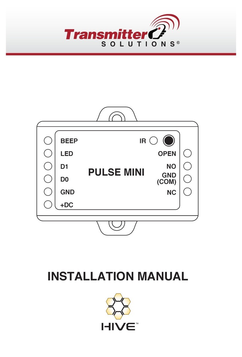
Transmitter Solutions
Transmitter Solutions Pulse Mini installation manual
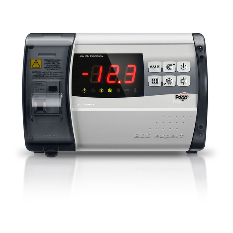
Pego
Pego ECP200 Expert d7.5 Use and maintenance manual
Protegus
Protegus SK232LED Brief user's guide
WAREMA
WAREMA climatronic Control panel 3 Series installation and connection
Hanna Instruments
Hanna Instruments BL 983321-0 instruction manual
Bosch
Bosch AMAX panel 2100 installation manual
