Vertiv Liebert DPM User manual

Liebert® DPM
User Manual

Vertiv™ | Liebert DPM
Technical Support Site
If you encounter any installation or operational issues with your product, check the pertinent section of this
manual to see if the issue can be resolved by following outlined procedures.
Visit https://www.Vertiv.com/en-us/support/ for additional assistance.
The information contained in this document is subject to change without notice
and may not be suitable for all applications. While every precaution has been
taken to ensure the accuracy and completeness of this document, Vertiv
assumes no responsibility and disclaims all liability for damages resulting from
use of this information or for any errors or omissions. Refer to other local
practices or building codes as applicable for the correct methods, tools, and
materials to be used in performing procedures not specifically described in this
document.
The products covered by this instruction manual are manufactured and/or sold
by Vertiv This document is the property of Vertiv and contains confidential and
proprietary information owned by Vertiv. Any copying, use or disclosure of it
without the written permission of Vertiv is strictly prohibited.
Names of companies and products are trademarks or registered trademarks of
the respective companies. Any questions regarding usage of trademark names
should be directed to the original manufacturer.

TABLE OF CONTENTS
1 Introduction 1
1.1 Touchscreen Control Panel and User Interface 1
1.2 Component Naming and Labeling 4
2 Touchscreen Display and User Interface 5
2.1 Restrict Physical Access with Barriers or Set Login Codes 6
2.1.1 Default PINs 6
2.2 SYSTEM PANEL: One-Line Display Components 9
2.3 Customizing the Display 10
2.3.1 Edit a View 10
2.3.2 Create a View 11
2.3.3 Remove a View 13
2.4 Using the Edit Icon to Customize Layout 13
2.4.1 Change Panel 14
2.4.2 Resize or Delete a Panel 14
2.4.3 Choose a Theme 15
3 Setting Display Properties 17
3.1 Setting Date, Time and Time Zone 18
3.2 Change the Time Zone 18
3.3 Change the Date 19
3.4 Changing Date, Time and Measurement Formats 19
3.4.1 Change the Date Format 19
3.4.2 Change the Time Format 19
3.4.3 Change the Measurement System 20
3.5 Create or Modify Custom Labels 20
4 Log In to the Touchscreen Control Panel 23
5 Context Menu Controls 27
5.1 Context Menu Commands for Operators 28
5.2 Context Menu Commands for Administrators 29
5.2.1 View or Change Network Settings 30
5.2.2 Change Input Contacts 32
5.2.3 Change Output Contacts 33
5.2.4 Configure Status Gauge 35
5.2.5 Settings - Unit 36
5.2.6 Settings - Import and Export 36
5.2.7 Import Settings 37
6 View System Status 39
6.1 View Overall System Status 39
6.2 View Component Status with One-Line Diagram Links 40
iii

6.2.1 Panelboard Status 40
6.2.2 Reset kWH 44
6.2.3 Reset Peak Demand 44
6.2.4 Reset Peak Current 45
6.2.5 View Transformer Configuration 45
7 Add, Remove and Configure Components 47
7.1 Change Component Configuration with One-Line Diagram Links 47
7.1.1 Panelboard Configuration: One-Line Diagram Links 47
7.1.2 Breaker Configuration: One-Line Diagram Links 49
7.2 Remove One Breaker from a Panelboard 50
7.3 Remove All Breakers from a Panelboard 52
7.4 Install Multiple Breakers 54
7.5 Change a Breaker 55
7.5.1 Add a Breaker 55
7.5.2 Set Breaker Details 56
8 Reset, Silence and Filter Faults and Events 59
8.1 Active EVENTS List: Overview 59
8.2 Event Log: Overview 59
8.3 Manage an Active Event 59
8.4 Filter Events: Active Events 61
8.5 Filter Events: Event Log 62
9 Vertiv™ Life™ Services 65
10 Faults, Warnings and Events 69
Vertiv™ | User Manual
iv

1 INTRODUCTION
The Vertiv™ Liebert® DPM offers the highest capability for control, communication and monitoring of power distribution
units and remote power panels (PDUs and RPPs).
The Touchscreen Control Panel’s integrated interface simplifies monitoring and managing the PDU or RPP where it is
installed. The control collects information about the PDU or RPP’s setup and operation and presents it in a standardized
format. This simple, dynamic display speeds operator response to changing power input and demand.
Many settings, including component names, number of inputs and other configuration items, will be made by Vertiv™
personnel when setting up the PDU or RPP and Liebert DPM. These will depend on the PDU or RPP model, its features and
site requirements. Many settings and component names can be modified by personnel with Administrator login access.
The Liebert DPM’s interface will display data either graphically or as text, whichever the user chooses (see Liebert® DPM
Main Display, Graphical View, Observer Level on page 2 and Liebert® DPM Main Display, Text View, Operator Level on
page 3). The display alternates between graphics and text at the touch of an icon. The one-line diagram remains
displayed and interactive, even when text view is chosen.
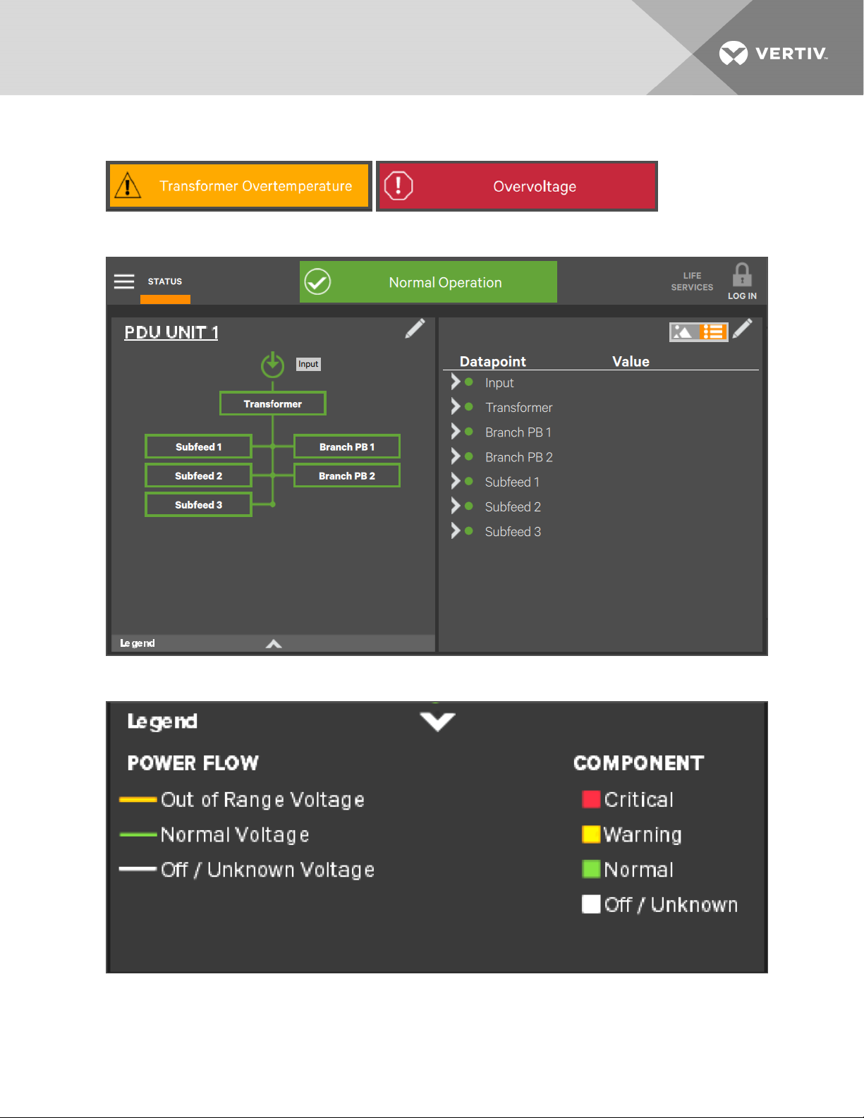
The Toolbar at the top of the touchscreen summarizes system conditions with colors and an icon matched to the status. The
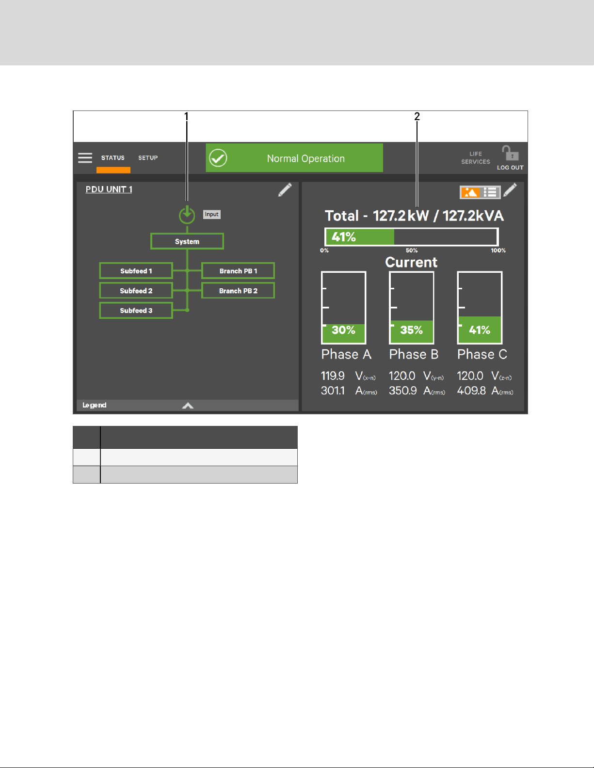
color and the icon change immediately if the system's status changes. The right panel displays meters showing data about
the output side of the transformer. The upper portion of the panel has the overall status. Below that is detailed output data
for each phase. See Figure 1.1 on the next page
1.1 Touchscreen Control Panel and User Interface
The Liebert DPM uses graphical icons or text to show the comprehensive information that the operator needs to keep the
system operating smoothly and efficiently:
•Is input power connected?
•Is the load balanced?
•Are there any alarms?
•Which breakers are open and which are closed?
Checking the status of a particular component is as simple as touching it on the one-line display. Detailed data appears,
allowing the operator to respond quickly to operational changes.
Visual and audible alarms alert personnel to faults and alarms requiring immediate attention. The legend drawer at the
bottom left of the main display in the Default View defines the color codes for unit status (see Legend, Graphical and Text
Views on page 3).
PINs (Personal Identification Numbers) for each access level - Operator, Administrator and Service - secure the Liebert
DPM against unauthorized changes. Observers (personnel without a PIN) can view PDU or RPP status through the Liebert
DPM, but cannot change any configuration settings.
1 Introduction 1

Figure 1.1 Liebert® DPM Main Display, Graphical View, Observer Level
ITEM DESCRIPTION
1 Context Menu icon
2 Active Navigation tab indicator - At Observer access level, no edit tools are displayed
3 Indicates which navigation tab is active
4 One-line system drawing; color-coded to indicate the status of each component
5 System status icon; changes to indicate overall status:Normal, Warning or Alarm
6
Toolbar, color-coded for system status; touching the status header will take you to the Events screen where any active events
may be viewed and managed; green indicates normal operation; amber denotes a warning and red denotes a critical fault; Toolbar
will scroll through active warnings and faults
7 Upper Meter showing output power usage for transformer
8 LIFE Services icon
9 Graphical/Text display switch
10 Login/Logout icon
11 Lower Meter showing output power usage for each phase; color-coded to indicate status
12 Legend Drawer icon
Vertiv™ | User Manual
2

Figure 1.2 System Status Toolbar: Warning and Alarm Examples
Figure 1.3 Liebert® DPM Main Display, Text View, Operator Level
Figure 1.4 Legend, Graphical and Text Views
1 Introduction 3

1.2 Component Naming and Labeling
Default component names are set either at the factory or by Vertiv Services personnel who set up the system, but
Administrators can rename them. Renaming permits site personnel to denote a component so that it's location and function
are more readily apparent (e.g., Rack # Backup Servers). There is no limit on the number of characters in the unit name;
panelboard names are limited to 32 characters and names for breakers and subfeeds can have no more than 24 characters.
Vertiv™ | User Manual
4

2 TOUCHSCREEN DISPLAY AND USER INTERFACE
The Liebert® DPM is active whenever the PDU or RPP it is mounted on has input power. The screen may be dark and
appear inactive, depending on its settings and user activity. If the panel is inactive, touch the LCD to activate it.
The touchscreen permits:
• Logging in to the system:Log In to the Touchscreen Control Panel on page 23
• Customizing the user interface:Customizing the Display on page 10
• Checking the status of the PDU or RPP, including all measured parameters, events and alarms: View System
Status on page 39
• Determining when users logged in and out:Context Menu Controls on page 27
• Silencing alarms:Reset, Silence and Filter Faults and Events on page 59
• Resetting faults:Reset, Silence and Filter Faults and Events on page 59
The Liebert DPM display's Default View has two panels:
•One-line diagram and
•Unit status (see Touchscreen DefaultView on page 6).
The Default View cannot be deleted. Editing the Default View is possible, but the changed view will be renamed
automatically and the original Default View will remain.
The Touchscreen Control Panel's appearance can be changed to multiple panes that show other data. Customizing the
appearance is detailed in Customizing the Display on page 10.
2 Touchscreen Display and User Interface 5

Figure 2.1 Touchscreen DefaultView
ITEM DESCRIPTION
1 One-Line Diagram
2 Unit Status
2.1 Restrict Physical Access with Barriers or Set Login Codes
NOTE: The default time for a login to remain active without screen interaction is 5 minutes. This is set when the unit
is configured. It can be altered at the Service level login.
The Liebert® DPM has four access levels—Observer, Operator, Administrator and Service—each with different levels of
authority. The Observer level, which does not permit configuration changes, does not require a PIN.
The default access level for the Liebert DPM is Observer. When a PIN is not required for the Administrator or Operator, the
control panel opens at the Administrator level.
2.1.1 Default PINs
•Observer: None at default level
•Operator: 1234 (default)
•Administrator: 2345 (default)
Vertiv™ | User Manual
6

Figure 2.2 Opening Screen - PINRequired
Figure 2.3 Opening Screen - No PIN Required; Opens to Administrator Level
To set or change a PIN:
1. Log in to the Liebert® DPM at the Administrator level (neither Observers nor Operators can change PINs).
2. Touch SETUP. The MANAGEPINNUMBERS menu opens; either the Operator or Administrator PIN may be
changed.
3. Touch the PINto be changed and a keypad opens.
4. Enter the new PIN or delete the numerals to delete PIN requirements.
5. Touch the OK button.
6. Touch the Save button to keep your changes or touch the Cancel button to exit without saving.
NOTE: To delete PIN requirements, such as for a PDU or RPP in a secure area with restricted access, remove the PIN
for the Operator level first, then delete the Administrator PIN. The Operator PIN must be empty before the
Administrator PINcan be deleted. If an attempt is made to delete the Administrator's PIN first, the Touchscreen
Control Panel will display a notice that the Operator's PIN is not empty. Conversely, the Administrator's PIN must be
completed first if conditions change and PINs become required.
2 Touchscreen Display and User Interface 7

Figure 2.4 Manage PINs
ITEM DESCRIPTION
1 Login level to be changed
2 PIN of level selected
3 Logout Icon
4Save button; , must be pressed to make complete changes
5OK button, must be pressed to proceed with changes
6Enter Key
7 Keypad
At login for all access levels, the Touchscreen Control Panel opens to the STATUS screen in graphic display. The STATUS
view at each login level will show the one-line diagram and system status readings unless the default view has been
changed. The appearance will differ only in the Context Menus displayed. The Observer and Operator menus are the same,
but the Observer has view-only access.
Context Menus are available by touching STATUS or an access level (SETUP for Administrator or SERVICEfor Service) and
then touching the Context Menu icon at the top left of the Touchscreen Control Panel. A label at the top of the Context Menu
signifies which level is being accessed. Touching a Context Menu item reveals data about a component or opens a submenu
with additional options (see Context Menu Controls on page 27).
Vertiv™ | User Manual
8

2.2 SYSTEM PANEL: One-Line Display Components
The one-line diagram, the default view for the control, shows each configured major component of the PDU or RPP system.
The one-line diagram displayed is the same for all access levels. Touching a component brings up details about that
component’s status. If the component has additional components, the one-line diagram shows those subcomponents with
overall details displayed in the right side of the touchscreen. Touch a lower-level component to view details about it.
Components in the one-line diagram signify their operational status by their color, green, white, amber or red. Faults,
Warnings and Events on page 69 describe the various states of the indicators.
The left panel default view can be changed from the one-line diagram to any of three other views: Status, Events and Event
Log (see Customizing the Display on page 10).
Figure 2.5 Typical One-Line Display - Normal Operation
ITEM DESCRIPTION
1 Unit Name
2 Input power
3 Transformer status
4 Edit Screen symbol
5 Legend drawer opener
6 System components
2 Touchscreen Display and User Interface 9

2.3 Customizing the Display
The Touchscreen Control Panel’s default appearance will be adequate for most installations, but the view can be altered to
show additional or different data. After creating or altering a view, select a view by touching the button beside it and touch
Save. The layout selected will be applied to all users. Layouts may be created or altered with Operator, Administrator or
Service Access if PINs are required. Observers, who do not have a PIN, do not have authority to customize the display.
To customize the display’s appearance:
1. Log in to the Liebert® DPM, with Operator, Administrator or Service Access if PINs are required.
2. From the STATUS view, touch the Context Menu icon in the top left corner.
3. Select Display Options > Customize Layout. (The right panel details how to edit, remove, or create a view; see
Editing, Creating or Removing Panel View on page 10.)
2.3.1 Edit a View
4. Touch a view to highlight it.
5. Touch Edit to change that view.
6. Alter the layout—Add or remove a panel or associate different options with a panel.
7. Touch the Save button to keep your changes or touch Cancel to exit without saving.
Figure 2.6 Editing, Creating or Removing Panel View
Vertiv™ | User Manual
10

ITEM DESCRIPTION
1 Increase or decrease the number of panels in the view
2 Screen instructions to change layout
3New panel layout button
4Save edited or new panel layout button
5Remove panel layout button
6Edit panel layout button
2.3.2 Create a View
1. Touch the New button to create a view.
2. Either accept the generated name (New View) or touch the view’s name to rename it using the on-screen
keyboard (maximum length is 15 characters including spaces). If more than one New View is created, the
Liebert® DPM will number them in order of creation.
3. Touch the Enter key on the on-screen keyboard after entering the new name.
4. Select the number of panels in the new or edited view from the drop-down list under the Layout heading. The
maximum is four, one for each possible view: OneLine, Status, Events, Event Log.
5. Choose the data to be displayed in each panel by touching a choice in the PANEL OPTIONS pane and then
touching the appropriate panel. Repeat for each panel.
6. Touch the Save button to keep the changes or touch the Cancel button to exit the screen without saving.
2 Touchscreen Display and User Interface 11

Figure 2.7 Create a Panel Layout
ITEM DESCRIPTION
1 Name for new layout
2 Number of panels in new layout
3 Content links for panels in new layout
4 Location of panels in new layout
Vertiv™ | User Manual
12

2.3.3 Remove a View
1. Select the view to be removed by touching in the view's row in the PANEL CONTENT screen.
2. Touch the Remove button at the bottom left of the PANEL CONTENT screen. The layout disappears.
3. Touch the Save button to complete the removal.
Figure 2.8 Remove a View
ITEM DESCRIPTION
1Edit button
2Remove button
3 View highlighted - may be edited or removed
2.4 Using the Edit Icon to Customize Layout
The Touchscreen Control Panel layout can also be changed with the Edit icons on the screen. The Edit icon can be
used to add or remove panels, resize panels, rearrange panels and change monitored parameters.
To use the Edit icon:
1. Log in as Operator or Administrator, if PINs are required.
2. Touch the Edit icon on the panel to be edited and hold it until a Change content button appears on the panel
(about 1 second).
2 Touchscreen Display and User Interface 13

2.4.1 Change Panel
3. Touch the Change content button. A window opens offering a choice of panel types not being displayed.
(Example:If the display is showing the one-line diagram and the Status panel, the choices offered will be
Events and Event Log.)
4. Choose the data to be displayed in the panel.
5. Touch an inactive portion of the screen to close the change options. The change will be applied automatically.
2.4.2 Resize or Delete a Panel
6. While the Change content button is displayed, touch the Edit icon. The panel will be selected with
handles and an Xwill appear (see Figure 2.9 on the facing page).
7. Resize a Panel: Pull or push a handle to resize the panel - this is possible only if the panel shares half the
Touchscreen Display with another panel (see Figure 2.9 on the facing page).
8. Move a Panel: Touching and holding the center circle (grabber circle) in a panel permits dragging the panel to
another area of the screen
9. Delete a Panel: Touch the Xon the panel to delete it from the layout. If only two panels are shown during this
operation, the remaining panel will fill the Touchscreen Display.
CAUTION: Deleting a panel with this method also removes that panel from the layout for all users. Choosing
this changed view from the Customize Layout menu shows a view without the panel that was deleted in
Steps 6through 9above. The panel can be restored to any layout through the steps in Customizing the
Display on page 10.
Vertiv™ | User Manual
14

Figure 2.9 Resize or Delete a Panel
ITEM DESCRIPTION
1 Panel to be resized or deleted
2 Handle for resizing the window (one of 8 handles)
3 Grabber Circle (moves panel to another area)
4 Delete panel icon
2.4.3 Choose a Theme
The Touchscreen Control Panel's default mode is a dark gray background with white headings and light gray text, dialog
boxes with dark gray text and orange indicators. This is the view shown in this document. This will be acceptable for most
applications, but it can be changed to a blue background or a light gray background, accompanied by changes to the
dialog boxes and text. Users at any access level, Observer, Operator, Administrator and Service, can choose a theme. The
selected theme will apply to the display at all access levels.
To choose a theme:
1. Touch the Context Menu and select Display Options, then Display Properties.
2. Touch the Theme dialog box and select a theme (see Figure 2.10 on the next page).
3. Touch the Save button. (The Save button becomes active only after a new theme has been chosen.
2 Touchscreen Display and User Interface 15

Figure 2.10 Choose a Theme
Figure 2.11 Themes: Light_Gray_9 and Blue_9
item DESCRIPTION
1 Light_Gray_9 theme
2 Blue_9 theme
Vertiv™ | User Manual
16
Table of contents
Other Vertiv Control Panel manuals
Popular Control Panel manuals by other brands

Rockwell Automation
Rockwell Automation Allen-Bradley OptixPanel 2800C AS Series user manual

Northern
Northern N-1000-III Installation and programming manual

Alarm Lock
Alarm Lock Eagle 8000 Series operating guide

Cattron
Cattron CANplus CP1000 Operation manual

Metso
Metso LCP9H Series Installation maintenance and operating instructions

Balboa
Balboa spaTouch series owner's manual