ESG-25U Progressive Type Safety Gear
Operating Instruction
Subject to change without notice! © Copyright WITTUR 2016
Sheet PM.7.005160.EN.04
Version -
Date 30.08.2019
Approved WAT/KKR
1. General information prior to installation
1.1 Description and functions
ESG-25U is an unidirectional progressive type safety
gear with mechanical and electrical components.
Mechanical components are consisting of a
combination of disk springs, braking elements and
trigger mechanism with movable roller. The safety gear
is activated by a compression spring. The electrical
components (magnets) are used to keep the safety gear
in initial position. In normal run operation the magnets
are powered to keep the activation spring compressed.
The main function of the safety gear is to safely stop
the elevator car in down-direction (acc. EN 81-20/50)
if the car speed exceeds predened nominal speed
irrespective what the reason for the increase in speed
may be. The device is adjusted (according to load and rail
conditions) and sealed in the factory. Later adjustments
will not be necessary and are in any case prohibited for
safety reasons. For installation always a pair of safety
gears is used.
1.1.1 Safety gear activation
If the car speed exceeds predened nominal speed
the activation of the safety gear is carried out by an
external speed control unit (see chapter 4.5), which is
cutting the power supply on magnets. This causes the
preloaded activation springs to expand and leads to
an engagement of the rollers. The elevator car will be
brought to a standstill holding tight at guide rails.
The speed control unit has to be a CE certied device(SIL
3 according EN 81-20 PESSRAL) or an alternative device
with the same high(or higher) security level. In case
of an alternative device, total safety system has to be
assessed.
1.1.2 Safety gear reset
To release the engaged safety gear, at rst emergency
rescue switch has to be switched on and power has to be
supplied to the magnets (reset speed control unit). The
elevator car has to be moved out of gripping in upward
direction with powered magnet. This process resets the
trigger mechanism in its initial position.
After switching off emergency rescue the reset process
is completed.
If safety gear is activated but not engaged (e.g.
power loss at standstill) an additional step has
to be carried out to reset the safety.
After emergency rescue switch activation and speed
control unit reset, the car has to be moved down with
recall drive until it is stopped by the safeties (rollers
engaged). In the following step the car is moved out of
gripping like mentioned above.
For elevators with safety gear mounted on the top of
the frame it is recommended to activate and program
parking position for an accessible landing. It has to
be ensured, that car roof is accessible in this parking
position.
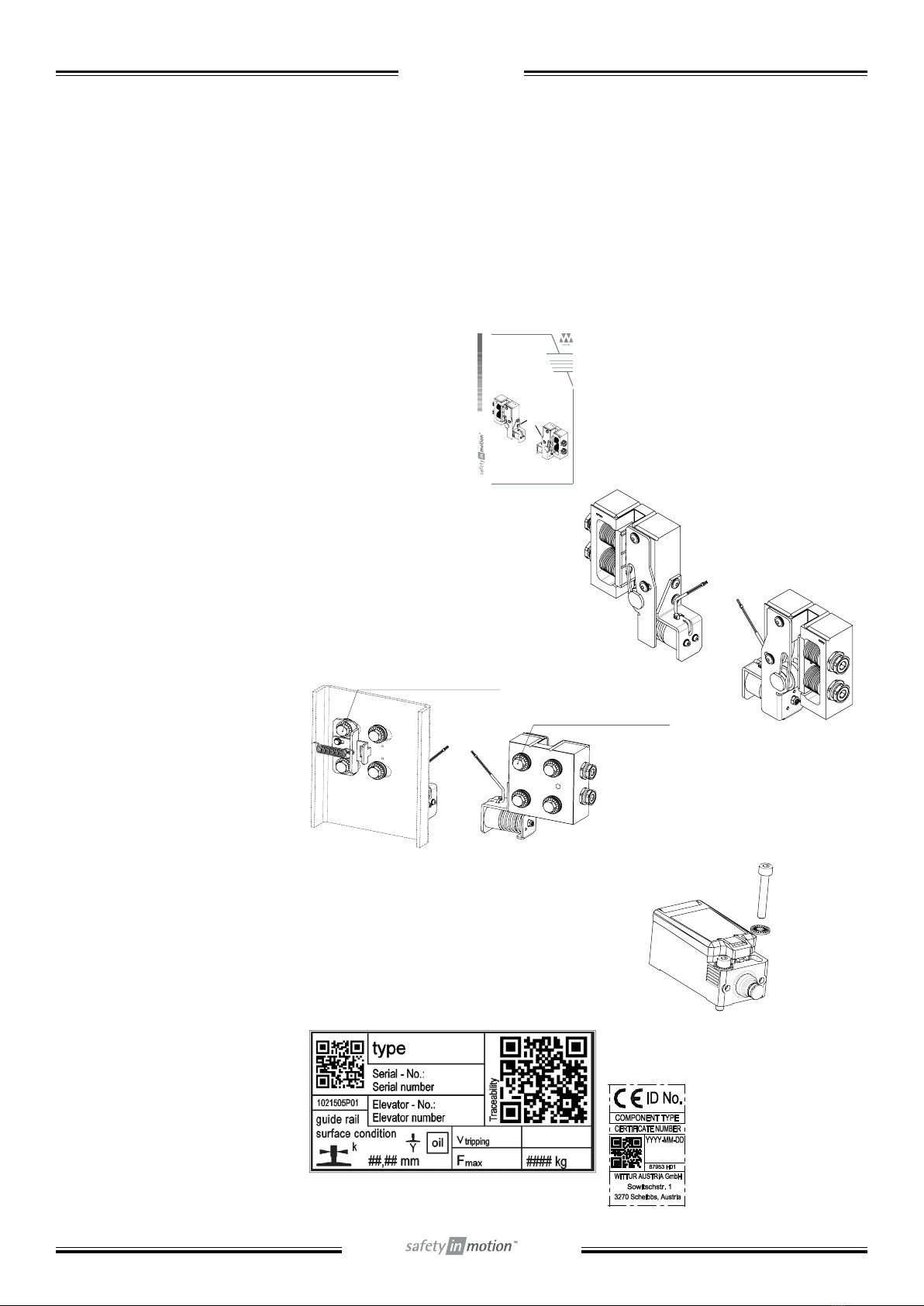
1. Brake lining
2. Safety gear block
3. Seal (sealing wax)
4. Adjustment screw
5. Disk spring assembly
6. Roller
7. Trigger mechanism
8. Magnet unit
1
2
3
4
5
6
7
8
1
2
+
0,50
0
4
±2
A2
1:1
SCALE
PRODUCT CODE
ESG
PRODUCT CATEGORY
7 - SAFETIES
ADD. DESCRIPTION
Safety gear
DESCRIPTION
1019552
DRAWING NUMBER
ESG-25U
GEOM. TOLERANCE SYMBOLS
ISO1101
A
FUNCTIONAL CLASS
GT2
GEN. TOLERANCE WST-00033
ISO1302
AT1DujaZ
DATE
1/1
DESIGNED BY
SHEET
REVISION
FIRST APPROVAL
DATE
DRAWN BY
©WITTUR HOLDING GmbH
A
B
C
D
E
F
12345678
The reproduction, distribution and utilization of this document as well as the communication of its contents to others without express authorization
is prohibited. Offenders will be held liable for the payment of damages. All rights reserved in the event of the grant of a patent, utility model or design.
V5.0
Revision Qty.
Description
Done by
Approved by
Date of issue
9 10 11 12
G
H
SURFACE TEXTURE SYMBOLS
SIZE
Change no.