OPERATION
Safety
12 | TEGREON 265-270 P www.stiebel-eltron.com
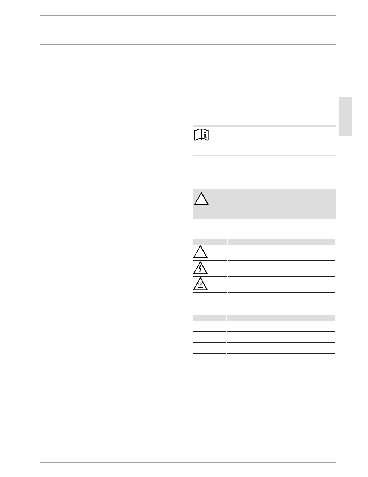
1.2 Other symbols in this documentation
Note
General information is identified by the adjacent symbol.
Read these texts carefully.
Symbol Meaning
Material losses
(appliance damage, consequential losses and environmen-
tal pollution)
Appliance disposal
This symbol indicates that you have to do something. The ac-
tion you need to take is described step by step.
1.3 Units of measurement
Note
All measurements are given in mm unless stated oth-
erwise.
2. Safety
2.1 Intended use
The module is designed for use in photovoltaic systems.
This appliance is intended for domestic use. It can be used safely
by untrained persons. The appliance can also be used in a non-do-
mestic environment, e.g.in a small business, as long as it is used
in the same way.
Any other use beyond that described shall be deemed inappropri-
ate. Observation of these instructions and of instructions for any
accessories used is also part of the correct use of this appliance.
We assume no liability for damage arising from failure to observe
these instructions, in particular the safety instructions, as well as
from misuse of the photovoltaic module.
2.2 General safety instructions
Please observe the following:
- Never use the module near easily combustible gases or va-
pours, as sparks may be produced.
- Never concentrate any sunlight artificially on the module.
- Never apply varnishes, paints or adhesives to the module.
- Never dismantle the module or remove any parts.
- Take into account the statics of the location of use.
- Only work under dry conditions.
- Secure modules to prevent them slipping or falling over.
- Never allow module to fall.
- Never hold modules by their switch panel or by the connect-
ing cables.
- Always lift modules by holding two opposite points of the
frame simultaneously. Never carry modules just by one part
of the frame.
- Never allow any objects to fall on the module.
- Never stand on the module.
- Only use undamaged modules.
- Ensure that no other system components are impairing the
modules mechanically or electrically.
- Never drill holes in the module frame or the glass surface
and never carry out any welding work on or directly near to
the modules.
!WARNING Injury
A second person who can provide help in the event of a
possible accident is required to be present for the entire
installation process.
!WARNING Injury
The appliance may be used by children aged 8 and older
and persons with reduced physical, sensory or mental
capabilities or a lack of experience and know-how, pro-
vided that they are supervised or they have been in-
structed on how to use the appliance safely and have
understood the resulting risks. Children must never play
with the appliance. Children must never clean the ap-
pliance or perform user maintenance unless they are
supervised.
2.3 Instructions, standards and regulations
Note
Observe all applicable national and regional regulations
and instructions.
The module fulfils the following standards:
- IEC/EN 61215 Edition 2
- IEC/EN 61730
2.4 Test symbols
See type plate on the module.
!