Foreseen
Use
Of
The
Tool
-
5062
Thisdie grinder isprimarilydesignedfor usewith
bonded
abrasive mountedpointgrindingwheels. It may also beusedwith steelrotary
filesand carbide
buns
providedtheir speed ratingmatches the speedof the grinder.
This tool should not be fitted withcut offwheels, saw blades, drill bits, etc. Ifthere Isany doubt about the correct use of this product
contactyour supplierfor advice.
Also makesure that the shank sizeof the attachmentto bedrivenmatcheswith thecolletsize fined inthegrinderandthat the maximum
allowedrunningspeed of the attachment exceedsthat marked onthegrinder.
There are special rulesgoverningthe use of bonded abrasivemountedpoint grindingwheels
-
for detailssee section "Operating."
Work
Stations
Thetoolshouldonlybe usedasa handheld, handoperatedtool. Itisalwaysrecommendedthat thetoolisusedwhenstandingona solid
floor.Itcanbeusedinother positions,but beforeany such use, the operatormustbeina secure positionhavinga firm grip and footing
andbe awareof the extra safetyprecautionsthat mustbe observed when usinggrindingmachines.
Putting Into Service
Air
Supply
Usea cleanlubricatedairsupplythat willgivea measuredairpressureat the toolof 90 PSiG(6.2 bar)when the tool isrunningwith the
trigger~leverfully depressed.Use recommendedhose size and length. Itis recommendedthat the tool Is connectedto the air supply as
shownInfigure 1.Do notconnectthetooltotheairlinesystemwithout Incorporatinganeasy to reachandoperateairshut off valve.The
air supplyshould belubricated. It is stronglyrecommendedthat an airfilter, regulator, lubricator
(FRL)
Isusedas shownin Figure
1
as
this will supply clean, lubricatedair at the correctpressureto the tool. Detailsof such equipment can be obtainedfrom your supplier.
If
suchequipmentIsnotused, thenthetoolshouldbelubricatedbyshuttingoff theairsupplyto thetool, depressurizingthelineby pressing
thetriggeronthetool.Disconnecttheairlineandpourintothehoseadaptorateaspoonful(5ml)of asuitablepneumaticmotorlubricating
oilpreferablyincorporatinga rustinhibitor.Reconnecttoolto airsupplyandruntoolslowlyfor a few seconds to allow air to circulatethe
oil. If tool isusedfrequently, lubricateon dailybasisandif tool starts to slow orlose power.
Itis recommendedthat the air pressureat the toolwhile the tool is runningis 90 PSU6.2 bar.
Usinga screwdriver, turnthevalve (8) untiltheslotalignswiththe
center
line
of the tool tor maxlmum speedgnd power and roiate
1
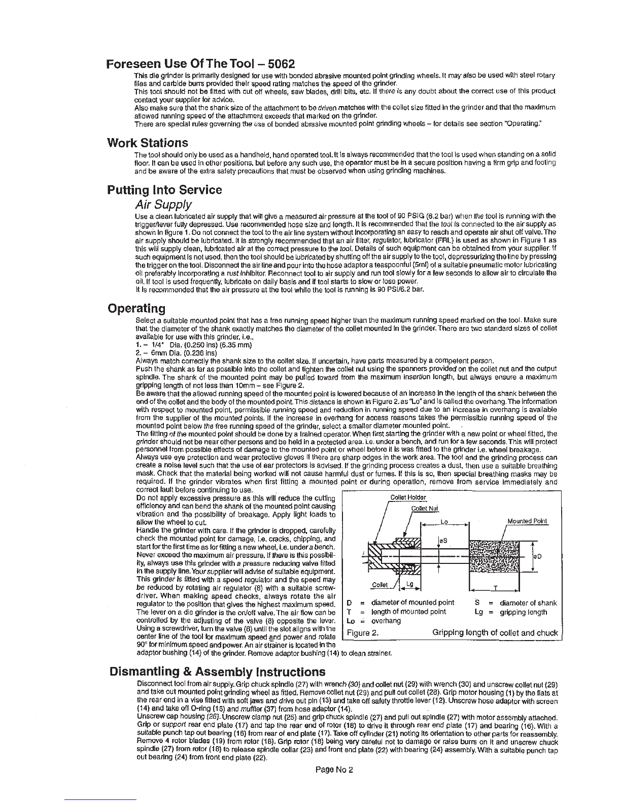
Figure
2'
Gripping length
of
collet
and
chuck
Operating
Selecta suitable mountedpoint that
has
a freerunningspeed higherthan the maximum runningspeedmarked onthe tool.Makesure
thatthe diameterof the shank exactly matches the diameterof thecolletmountedInthe grinder.There are two standardsizes of collet
available for usewiththis grinder, i.e.,
1.
-
114" Dia.(0.250 ins)
(6.35
mm)
2.
-
6mm Dia. (0.236 ins)
Always matchcorrectlythe shank size to the colletsize. Ifuncertain, have partsmeasuredby a competent person.
Pushthe shank
as
far
as possibleintothe colietand tightenthe collet nut usingthe spannersprovidedon the colletnutandthe output
spindle. The shank of the mounted point may be pulledtoward from the maximum insertionlength, but always ensure a maximum
grippinglengthof notlessthan 10mm
-
see Figure2.
Beawarethattheallowedrunningspeedofthe mountedpointisloweredbecauseof anIncreaseInthe iengthof the shank betweenthe
endof thecolletandthe bodyofthemountedpoint.Thisdistance isshowninFigure2.asULo'and iscalledthe overhang.Theinformation
with respectto mountedpolnt, permissiblerunningspeed and reductionin running speed due to an increase inoverhangis available
from the supplier of the mountedpoints. It the Increasein overhang for access reasons takes the permissible running speed of the
mountedpoint belowthe free runningspeedof thegrinder, select
a
smallerdiameter mountedpoint.
The fitting of the mountedpointshould be done by
a
trainedoperator.Whenfirst startingthe grinderwitha newpointorwheel fitted, the
grindershouldnotbenearotherpersonsandbe heldin
a
protectedarea. 1.e. under
a
bench,and runforafew seconds.This willprotect
personnelfrompossibleeffects of damageto the mountedpolntor wheel before itiswas fitted to the grinderi.e. wheel breakage.
Always use
eye
protectionandwear protective gloves
If
there are sharp edges inthework area. Thetool and the grinding process can
create
a
noiselevelsuchthat the useof ear protectorsis advised.If the grindingprocesscreates
a
dust, then usea suitablebreathing
mask. Check that the materialbeingworked will not cause harmfuldust or fumes. If this is so, then special breathingmasks may be
required. If the grinder vibrates when first fitting
a
mounted point or during operation, remove from service immediately and
90'
for minimumspeedandpower.Anairstrainerislocatedinthe
adaptorbushing(14)of thegrinder. Removeadaptorbushing
(14)
to cleanstrainer.
correctfault beforecontinuingto use.
Do notapply excessive pressureas this will reduce the cutting
efficiencyandcanbendthe shankof the mountedpointcausing
vibration and the possibilityof breakage. Apply light loads to
allowthe wheel to cut.
Handlethe grinderwith care. If the grinder is dropped, carefully
check the mountedpolnt for damage, 1.0. cracks, chipping,
and
startfor thefirsttimeasforfittinganewwheel, i.e. underabench.
Neverexceedthemaximumairpressure.Ifthereisthis possibii-
ity, alwaysuse this grinder with
a
pressurereducing
valve
fitted
inthesupplyline.Your supplierwilladviseof suitableequipment.
This grinderIs liltedwith
a
speed regulatorand the speedmay
be reduced by rotating alr regulator (8) with a suitable screw-
driver. When making speed checks, always rotate the air
regulatorto the positionthat gives the highest maximumspeed.
The lever on a die grinder is the ontoffvalve,Thg air flow
can
be
controlled by the adiustino of the valve
(81
ODDOS~~~
the lever.
Dismantling
&
Assembly
Instructions
Disconnecttoolfromairsupply.Gripchuckspindle (27)with wrench
(30)
andcolletnut(29)withwrench
(30)
andunscrewcolletnut(29)
andtake out mountedpointgrindingwheel as fitted.Removecolletnut
(29)
andpulloutcollet (28).Grip motor housing
(1)
bythe flats at
therearendIna vise fittedwithsoftjaws and driveout pin(13)andtake off safetythrottlelever(12).Unscrewhoseadaptorwithscreen
(14)
and
take
offO-ring (15)and muffler (37) from hoseadaptor
(14).
Unscrewcap housing(26).Unscrewclamp nut
(25)
andgripchuckspindle(27)andpullout spindle(27) with motorassemblyattached.
Gripor support rear end plate (17) andtap the rear end of rotor (18) to drive it through rear end plate (17) and bearing (16). With a
suitablepunchlap out bearing
(16)
fromrearof endplate (17).Takeoff cylinder(21) noting
US
orientationto other partsfor reassembly.
Remove
4
rotorblades
(19)
from rotor
(18).
Grip mtor (18) being
very
careful notto damage or raise burrs on it and unscrew chuck
spindle (27)from mtor (18)to releasespindlecollar (23) andfmnf endplate
(22)
with bearing(24) assembly.Witha suitablepunchtap
out bearing(24) fromfront end plate (22).
Collet
Holder
D
=
diarderof~'~~ountedpoint
S
=
diameterof shank
T
=
lengthofmountedpoint Lg
=
gripping length
Lo
=
overhand
Page
No
2


