manuals.online logo
Brands
  1. Home
  2. •
  3. Brands
  4. •
  5. SIP
  6. •
  7. Fan
  8. •
  9. SIP 05634 User manual

SIP 05634 User manual

20
Ref: 23JUL2021
FOR HELP OR ADVICE ON THIS PRODUCT PLEASE CONTACT YOUR DISTRIBUTOR,
OR SIP DIRECTLY ON:
TEL: 01509500400
EMAIL: sales@sip-group.com or technical@sip-group.com
www.sip-group.com
Please dispose of packaging for the product in a responsible
manner. It is suitable for recycling. Help to protect the
environment, take the packaging to the local amenity tip and
place into the appropriate recycling bin.
Never dispose of electrical equipment or batteries in with your
domestic waste. If your supplier offers a disposal facility please
use it or alternatively use a recognised re-cycling agent. This
will allow the recycling of raw materials and help protect the
environment.
1
Drum Fans
05634, 05636 & 05638
Please read and fully understand the instructions in this manual
before operation. Keep this manual safe for future reference.
2
19
Declaration of Conformity
We
SIP (Industrial Products) Ltd
Gelders Hall Road
Shepshed
Loughborough
Leicestershire
LE12 9NH
England
As the manufacturer's authorised representative within the EC
declare that the
24” Drum Fan - SIP Part. No. 05634
30” Drum Fan - SIP Part No. 05636
36” Drum Fan - SIP Part No. 05638
Conforms to the requirements of the following directive/s, as indicated.
2014/35/EU Low Voltage Directive
2014/30/EU EMC Directive
2011/65/EU RoHS Directive
As Amended By
(EU) 2015/863
And the relevant harmonised standard(s),
including:
EN 55014-1:2017
EN 55014-2:2015
EN 61000-3-2:2014
EN 61000-3-3:2013
EN 60335-1+A11:2014+A13:2017
EN 60335-2-80:2003+A1:2004+A2:2009
EN 62233:2008
Signed: …………………………………...
Mr P. Ippaso - Director - SIP (Industrial Products) Ltd
Date: 23/06/2021.
DECLARATION OF CONFORMITY
And Regulation/s.
(EU) 327/2011 Implementing Directive 2009/125/EC with regard to
And ecodesign requirements for fans driven by motors.
(EU) 2016/2282
18
3
CONTENTS
Page No. Description
4. Safety Symbols Used Throughout This Manual
4. Safety Instructions
6. Electrical Connection
8. Technical Specifications
9. Guarantee
9. Contents and Accessories
10. Getting To Know Your Drum Fan - 05634
11. Getting To Know Your Drum Fan - 05636 & 05638
12. Operating Instructions
13. Wiring Diagram
14. Exploded Drawing / Parts List - 05634
15. Exploded Drawing / Parts List - 05636
16. Exploded Drawing / Parts List - 05638
18 & 19.
UK & EU -
Declaration of Conformity
UK - DECLARATION OF CONFORMITY
Declaration of Conformity
We
SIP (Industrial Products Ltd
Gelders Hall Road
Shepshed
Loughborough
Leicestershire
LE12 9NH
England
As the manufacturer within the UK, England, Scotland & Wales, declare
that the
Conforms to the requirements of the following regulation(s), as indicated
Signed: …………………………………...
Mr P. Ippaso - Director - SIP (Industrial Products) Ltd
Date: 23/06/2021
24" Drum Fan - SIP Part. No. 05634
30" Drum Fan - SIP Part. No. 05636
36" Drum Fan - SIP Part. No. 05638
Electrical Equipment (Safety) Regulations 2016
Electromagnetic Compatibility Regulations 2016
The Restriction of the Use of Certain Hazardous Substances in
Electrical and Electronic Equipment Regulations 2012
The Ecodesign for Energy-Related Products and Energy Information
(Amendment) (EU Exit) Regulations 2019
and the relevant harmonsed standards
BS EN 55014-1:2017
BS EN 55014-2:2015
BS EN 61000-3-2:2014
BS EN 61000-3-3:2013
BS EN 60335-1+A11:2014+A13:2017
BS EN 60335-2-80:2003+A1:2004+A2:2009
BS EN 62233:2008
4
When using your fan, basic safety precautions should always be followed to reduce
the risk of fire, electric shock, personal injury and / or damage to the fan.
Read all of these instructions before operating the fan and save this user manual for
future reference.
The fan should not be modified or used for any application other than that for which it
was designed; It was designed to safely and quietly move air in large volumes.
If you are unsure of its relative applications do not hesitate to contact us and we will
be more than happy to advise you.
Before operating the fan always check no parts are broken, that all screws are com-
pletely tight and that no parts are missing.
Always operate the fan safely and correctly.
KNOW YOUR FAN: Read and understand the owner's manual and labels affixed to the
fan. Learn its applications and limitations, as well as the potential hazards specific to
it.
DO NOT USE THE FAN IN DANGEROUS ENVIRONMENTS: Do not use your fan in damp or
wet locations, or expose it to rain. Always provide adequate space around the drum
fan.
STAY ALERT: Always watch what you are doing and use common sense when placing
and operating the fan.
DISCONNECT THE FAN FROM THE MAINS SUPPLY: When not in use.
NEVER LEAVE THE FAN UNATTENDED: During operation.
DO NOT ABUSE THE MAINS LEAD: Never pull the mains lead to remove the plug from
the mains socket, or to move the fan from place to place. Keep the mains lead
SAFETY SYMBOLS USED THROUGHOUT THIS MANUAL
SAFETY INSTRUCTIONS
Important: Please read the following instructions carefully, failure to do
so could lead to serious personal injury and / or damage to the drum
fan.
Note: Supplementary Information.
Danger / Caution: Indicates risk of personal injury and/or the possibility of
damage.
Warning: Risk of electrical injury or damage!
17
NOTES
16
EXPLODED DRAWING / PARTS LIST
05638
1
2 3 4 5 6 7 8 9 10 11 12 13 14
15
16
No. Description SIP Part No. No. Description SIP Part No.
1. Front guard PW10-00113 10. Support A PW10-00116
2. Fan blade PW10-00114 11. Support B PW10-00117
3. Spacer PW10-00092 12. Capacitor PW10-00118
4. Bracket PW10-00093 13. Motor PW10-00119
5. Handle A PW10-00122 14. Rear Grill PW10-00120
6. Drum Body PW10-00115 15. Handle B PW10-00123
7. Switch PW10-00101 16. Frame PW10-00121
8. Switch Knob PW10-00102 N/A Main Lead PW10-00099
9. Switch Box PW10-00098
5
away from heat, oil and sharp edges. If the mains lead is damaged, it must be re-
placed by the manufacturer or its service agent or a similarly qualified person in order
to avoid unwanted hazards.
HAVE YOUR FAN REPAIRED BY A QUALIFIED PERSON: The fan is in accordance with the
relevant safety requirements. Repairs should only be carried out by qualified persons
using original spare parts, otherwise this may result in considerable danger to the user
and void the warranty.
USE RECOMMENDED PARTS ONLY: Unapproved and untested parts may be danger-
ous and will invalidate the warranty.
 DANGER! Check that the fan is in sound condition and good working order. Take
immediate action to repair or replace damaged parts.
 WARNING! Only operate on a level and stable surface.
 WARNING! Do not allow untrained persons to operate the fan and do not operate
the fan without all covers etc. correctly fitted.
 WARNING! RISK OF ELECTRIC SHOCK. Do not expose the fan to water spray, rain,
dripping water or moisture of any kind.
 Do not leave the fan unattended when in use. Switch the fan off and unplug from
the mains supply before leaving the work area.
 Do not allow children or animals near the drum fan, particularly when in use.
 Ensure that the drum fan is correctly turned off when not in use and store in a safe,
dry area, out of reach of children.
 Keep all combustible materials away from this drum fan.
 Never stand on the fan.
 DO NOT dismantle or tamper with the fan, this may be dangerous and will invalidate
the warranty.
WARNING: Risk of Electric Shock!
 Use only the electrical power (voltage and frequency) specified on the model plate
of the drum fan. If in doubt contact the manufacturer.
 Use only a three-prong, grounded (earthed) outlet.
 Do not touch, or operate the fan when your hands are wet.
 Those who are not qualified electricians / engineers should not disassemble, repair or
rebuild the fan.
 DO NOT unplug the fan by pulling the mains lead. Unplug by holding the plug.
 DO NOT use the fan when there is damage to the mains lead or plug.
 DO NOT use the fan close to the fires.
 To reduce the risk of fire or electric shock, do not use this fan with any solid-state
speed control device.
 DO NOT use the fan outdoors.
 Always check all guards to make sure they are secure before starting the fan.
SAFETY INSTRUCTIONS….cont
6
 Never insert fingers or any other object/s through the grill guard when the fan is in
operation.
 Never leave the fan unattended and ensure that children and pets are kept a safe
distance from the fan.
 Turn the fan off and disconnect it from the mains supply when moving from one lo-
cation to another.
 Turn the fan off and disconnect it from the mains supply when carrying out any re-
pairs, maintenance or cleaning.
 Do not use petrol or other corrosive liquids for cleaning as they may damage the fan
or outer casing / grill.
 Do not operate the fan near an open window, such as on a window sill; rain or mois-
ture may create an electrical hazard.
 Never modify the fan in any way.
 Never operate the fan without all guards in place.
 Before each use; always check that the moving parts move freely and do not catch
or bind.
 Stop operation immediately if abnormalities are noticed.
 Always clear the surface around where the fan is to be used to avoid unwanted dust
or debris being pulled through the fan.
If a problem with the drum fan is experienced, or if the mains lead or plug become
damaged, contact your distributor for repair.
If the drum fan is used in a place of work all rules and laws etc. relating to the use of
portable electrical appliances should be followed.
Understand the operating environment; Before each use the operator should assess,
understand and where possible reduce the specific risks and dangers associated with
the operating environment. Bystanders should also be made aware of any risks associ-
ated with the operating environment.
WARNING! It is the responsibility of the owner and the operator to read, understand
and comply with the following:
You must check all electrical products, before use, to ensure that they are safe.
You must inspect power cables, plugs, sockets and any other connectors for wear or
damage.
You must ensure that the risk of electric shock is minimised by the installation of appro-
priate safety devices; A residual current circuit Breaker (RCCB) should be incorporated
SAFETY INSTRUCTIONS….cont
CAUTION: The warnings and cautions mentioned in this user manual can not cover all possible
conditions and situations that may occur. It must be understood by the operator that common
sense and caution are factors which cannot be built into this product, but must be applied.
ELECTRICAL CONNECTION
15
EXPLODED DRAWING / PARTS LIST
05636
1
2 3 4 5 6 7 8 9 10 11 12 13 14
15
16
No. Description SIP Part No. No. Description SIP Part No.
1. Front guard PW10-00113 10. Support A PW10-00116
2. Fan blade PW10-00114 11. Support B PW10-00117
3. Spacer PW10-00092 12. Capacitor PW10-00118
4. Bracket PW10-00093 13. Motor PW10-00119
5. Handle A PW10-00122 14. Rear Grill PW10-00120
6. Drum Body PW10-00115 15. Handle B PW10-00123
7. Switch PW10-00101 16. Frame PW10-00121
8. Switch Knob PW10-00102 N/A Main Lead PW10-00099
9. Switch Box PW10-00098
14
EXPLODED DRAWING / PARTS LIST
05634
1
2
3 4
5
6
7 8 9 10 11 12
13
No. Description SIP Part No. No. Description SIP Part No.
1. Front guard PW10-00090 8. Motor PW10-00097
2. Fan blade PW10-00091 9. Switch Box PW10-00098
3. Spacer PW10-00092 9A. Mains Lead PW10-00099
4. Bracket PW10-00093 10. Capacitor PW10-00100
5. Handle PW10-00094 11. Switch PW10-00101
6. Drum Body PW10-00095 12. Switch Knob PW10-00102
7. Rear Guard PW10-00096 13. Frame PW10-00103
7
in the main distribution board. We also recommend that a residual current device
(RCD) is used. It is particularly important to use an RCD with portable products that are
plugged into a supply.
Connecting to the power supply:
These SIP drum fans are fitted with a standard 230v ~ 13 amp type plug. Before using
the drum fan, inspect the mains lead and plug to ensure that neither are damaged. If
any damage is visible have the drum fan inspected / repaired by a suitably qualified
person. If it is necessary to replace the plug a heavy duty impact resistant plug would
be preferable.
The wires for the plug are coloured in the following way:
Yellow / green Earth
Blue Neutral
Brown Live
As the colours of the wires may not correspond with the markings in your plug, pro-
ceed as follows: The wire which is coloured blue, must be connected to the terminal
marked with N or coloured black. The wire which is coloured brown, must be connect-
ed to the terminal, which is marked L or coloured red. The wire which is coloured yel-
low / green should be connected to the terminal which is coloured the same or
marked
Always secure the wires in the plug terminal carefully and tightly. Secure the cable in
the cord grip carefully.
ELECTRICAL CONNECTION….cont
Warning: Never connect live or neutral wires to the earth terminal of the plug.
Only fit an approved plug with the correct rated fuse. If in doubt consult a quali-
fied electrician.
Note: Always make sure the mains supply is of the correct voltage and the
correct fuse protection is used. In the event of replacing the fuse always
replace the fuse with the same value as the original.
8
Note: The cross section of the extension lead should be checked so that it
is of sufficient size so as to reduce the chances of voltage drops.
Note: If an extension lead is required in order to reach the mains supply;
ensure that this too is rated for the correct voltage and fuse rating.
ELECTRICAL CONNECTION….cont
TECHNICAL SPECIFICATION
Item No. 05634 05636 05638
Supply 220-240V ~ 50Hz
No. of Speed Settings 2
Power Consumption (W) - Low 270 Watts 275 Watts 390 Watts
Power Consumption (W) - High 330 Watts 315 Watts 410 Watts
Input Current (A) - Low 1.17 A 1.24 A 1.77 A
Input Current (A) - High 1.45 A 1.37 A 1.86 A
Overall Efficiency 31.40% 32.15% 31.75%
Measurement Category A
Efficiency Category Static
Efficiency Grade 40.30 41.22 40.21
VSD No
Service Value 0.36 m³/ Min/W 0.54 m³/ Min/W 0.54 m³/ Min/W
Fan Ø 24" (610mm) 30" (762mm) 36” (914mm)
Air Flow - Low 6440 m³/Hour 7620 m³/Hour 9905 m³/Hour
Air Flow - High 7128 m³/Hour 10160 m³/Hour 13205 m³/Hour
Speed - Low 1300 rpm 880 rpm 860 rpm
Speed - High 1420 rpm 960 rpm 950 rpm
Noise Level (Max.) 87 dB(A) 84 dB(A) 84 dB(A)
Protection IP20
Net Weight 19.8 Kg 34.19 Kg 40.5 Kg
13
WIRING DIAGRAM
12
Note: Never Run this fan whilst it`s raining, or in any damp or wet locations,
and never place it on the window sill.
The drum fan has 2 different speed settings:
0 --- Stop
1 --- Low
2 --- High
 Turn the switch to the desired position1 or 2 to start the fan.
 Turn the switch to “0” to stop the fan running.
1 Metre minimum Wall
OPERATING INSTRUCTIONS
Note: Always allow at least 1 metre clearance around the fan, failure to
adhere to this will stop the cooling air flowing through the drum fan, this
could damage the motor and void your warranty.
9
1x Drum Fan.
1x Instruction Manual.
These SIP drum fans are covered by a 12 month parts and labour warranty covering
failure due to manufacturers defects. This does not cover failure due to misuse or op-
erating the fan outside the scope of this manual - any claims deemed to be outside
the scope of the warranty may be subject to charges Including, but not limited to
parts, labour and carriage costs. Consumables items such as fuses are not covered
by the warranty.
In the unlikely event of warranty claims, contact your distributor as soon as possible.
GUARANTEE
Note: Proof of purchase will be required before any warranty can be hon-
oured.
Note: If any of the above are missing or damaged, contact your distribu-
tor immediately.
CONTENTS & ACCESSORIES
10
B
A
GETTING TO KNOW YOUR DRUM FAN
05634
Front
Rear
Ref. Description Ref. Description
A. Speed control knob E. Frame
B. Motor F. Foot
C. Handle G. Wheels
D. Drum Body H. Fan Blade
C
D
E
F
G
H
C
11
GETTING TO KNOW YOUR DRUM FAN
05636 & 03638
A
Ref. Description Ref. Description
A. Speed control knob E. Frame
B. Motor F. Foot
C. Handle G. Wheels
D. Drum Body H. Fan Blade
B
D
E
F
G
H
C
C

This manual suits for next models

2

Other SIP Fan manuals

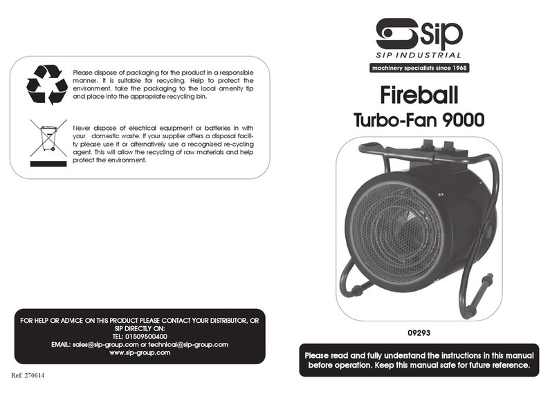
SIP Fireball Turbo-Fan 9000 User manual

SIP

SIP Fireball Turbo-Fan 9000 User manual

SIP 05639 User manual

SIP

SIP 05639 User manual

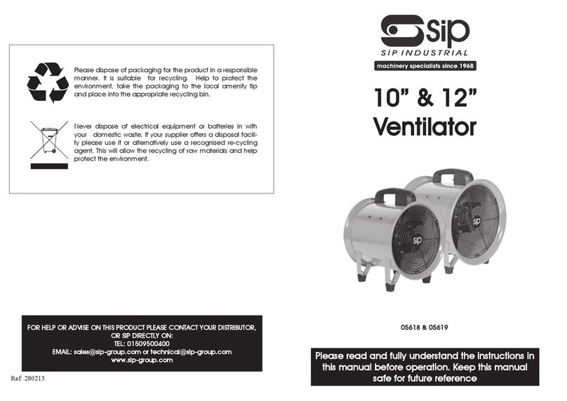
SIP 05618 User manual

SIP

SIP 05618 User manual

SIP 05645 User manual

SIP

SIP 05645 User manual

Popular Fan manuals by other brands

Regulus HR 30W User's installation and operation manual

Regulus

Regulus HR 30W User's installation and operation manual

NuTone InVent AERN110SL Installation and Use & Care Instructions

NuTone

NuTone InVent AERN110SL Installation and Use & Care Instructions

Lasko 2535 operating manual

Lasko

Lasko 2535 operating manual

OSTBERG LPFB Directions for use

OSTBERG

OSTBERG LPFB Directions for use

NuTone Roomside / Flex Series instructions

NuTone

NuTone Roomside / Flex Series instructions

Schuller 168304D installation guide

Schuller

Schuller 168304D installation guide

Click TF-A02 instruction manual

Click

Click TF-A02 instruction manual

Fan-Tastic Vent 3300 Operation guide

Fan-Tastic Vent

Fan-Tastic Vent 3300 Operation guide

Parrot Uncle F6222 Installation & operating instructions

Parrot Uncle

Parrot Uncle F6222 Installation & operating instructions

Patron FL-2 product manual

Patron

Patron FL-2 product manual

Lifebreath HRV Series Homeowner's manual

Lifebreath

Lifebreath HRV Series Homeowner's manual

HELLER HPF50W instruction manual

HELLER

HELLER HPF50W instruction manual

Canarm DELHI 300 Series Operation instructions and parts manual

Canarm

Canarm DELHI 300 Series Operation instructions and parts manual

Monte Carlo Fan Company 5EPR60BRD Series owner's manual

Monte Carlo Fan Company

Monte Carlo Fan Company 5EPR60BRD Series owner's manual

Hunter 43045 installation guide

Hunter

Hunter 43045 installation guide

ECRON RD40 AC user manual

ECRON

ECRON RD40 AC user manual

Moro ES 4 INSTRUCTIONS FOR THE USE AND THE MAINTENANCE

Moro

Moro ES 4 INSTRUCTIONS FOR THE USE AND THE MAINTENANCE

Bionaire BW2300 Instruction leaflet

Bionaire

Bionaire BW2300 Instruction leaflet

manuals.online logo
manuals.online logoBrands
  • About & Mission
  • Contact us
  • Privacy Policy
  • Terms and Conditions

Copyright 2025 Manuals.Online. All Rights Reserved.