Siqura MC 11 Operating instructions

MC 11 EB-2
Power supply cabinet with external bus, AC version
USER/MAINTENANCE MANUAL
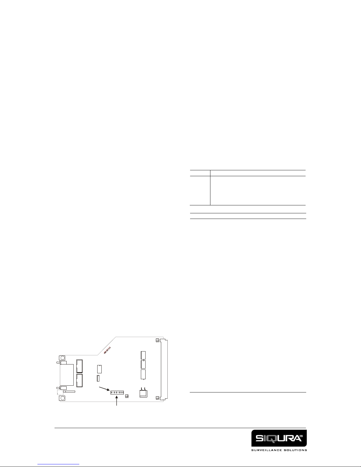
Figures 1a, b, c. Module mounting (a) and fan sides (b) of MC 11 AC EB-2 cabinet, and (c) slot 0 panel.
1. General description
REFER TO SECTION 10 FOR SAFETY AND EMC
RELATED ITEMS FIRST
The MC 11 AC EB-2 19" power supply cabinet
with external bus has 11 free slots for Siqura plug-
in modules (7TE), supplying these with the correct
DC voltages. The 'mains' power connector module
in the remaining, dedicated slot 0 contains a
microprocessor. This processor is used for:
- status monitoring and controlling of SNM
compatible modules and those from the AWS
3000 series in the cabinet;
- controlling two relays;
- reading status information of the cabinet proper.
Two RS-485 serial bus interfaces to the processor
are provided, allowing remote system management
and control. By way of these interfaces, a large
number of MC XX EB-2 cabinets may be linked
with shielded 4(+1 ground)-wire data cable. More
information on system control can be found in
supplementary manuals; the cabinet can be set to
EB compatibility.
The 230 or 120 Vac-powered MC 11 AC EB-2
internals are cooled with two fans. Note that the
cabinet mounting brackets can be put on the module
side or on the fan side (see figures 1a,b).
2. Indicators and connectors
In figure 1a, SLOT 0-SLOT 11 indicate the twelve
module slots. An external earthing point (1) is
provided on one shorter cabinet side.
The front panel of the controller module has two
9-pin D-connectors for serial (external) com-
munications, and two 2-pin relay connections 1 and
2 combined into one connector (see figures 1a, c
and table 1).
The controller module front panel furthermore
provides a mains connector and an access panel for
the mains fuse (figures 1a,c and 4).
(AC connector)
mains connector
(fuse)
power fuse holder
strain relief stud (M4)
CC o
(4-p Combicon)
relay contacts 1, 2
DATA o
, 9-pin fem. D-
connector, 2x
RS-485 serial interfaces
(1 active in EB-1 mode)
Status LEDs
*DC (green)
DC power OK (internal)
*EB (green)
control data I/O
*1 (red)
relay 1 activated
*2 (red)
relay 2 activated
Table 1. Panel layout of module S0. Note: the relay
contacts are open when the MC 11 EB-2 is not powered.
3. Installation instructions for EB-2 mode
1. Choose the mode of operation (EB-2 absolute
addressing, EB-2 local addressing, or EB
compatibility mode, see §5).
2. Mount the MC 11 EB-2 cabinet into a standard
19-inch rack, without modules in the slots. Check
whether the specified power voltage of the cabinet
matches the local power supply voltage.
(a)
(b)
(c)
MC11
SLOT 1 SLOT 2 SLOT 3 SLOT 4 SLOT 5 SLOT 7 SLOT 8 SLOT 9
SLOT 6 SLOT 10 SLOT 11
EB-2
SLOT 0
1
© Siqura 2016
Version 041808-2d
MC11AC EB-2 (MW10)
2
Note: to prevent overheating of the cabinet and
inserted modules, provide air circulation room at
the cabinet front and rear (10 cm) and bottom (1
cm).
3. The chassis should be connected to safety ground
utilising the connection on the side wall of the
cabinet (1 in figure 1a).
4. Fasten the power cord to the strain relief stud
(see the hexagons in figures 1a and c, top).
5. Connect the power cord to the power supply and
switch on power. The electric fans should be
working; if not, disconnect power immediately
and check the power voltage.
6. Power off the cabinet and install the Siqura
modules according to the instructions given in the
user manuals of the modules. Slots not in use
should be covered with 7TE blanking plates (BF
07).
7. Power on the cabinet. Both fans should be
working, blowing outwards.
4. Care, maintenance and safety
For reliable operation of the module, observe the
following:
- prevent dust from collecting on the equipment
- protect the equipment against moisture
- maintain sufficient cooling space around the
equipment (see §3).
- replace the electric fans every 5 years. Consult
section 7 on how to replace fans.
- replace blown fuses only with the types specified.
Consult section 8 on how to change fuses.
For ultimate safety, one should not remove, add or
exchange modules while the power supply cabinet
is operating. If a module causes a DC short on the
secondary (output) side, the MC 11 will turn itself
off; it can be restarted by taking power off for at
least 4 seconds, then connecting it again.
5. Configuring the cabinet
5.1. General
There are two basic operating modes: SNM (also
loosely called EB-2) and EB (the latter providing
compatibility with the older EB protocol; for EB
configuration see §5.3). Dip switches are used to set
modes and parameters, which are not identical for
the two modes. The dip switches for setting the
parameters of MC 11 EB-2 cabinets are located on
the board inside the module in the dedicated slot 0
(the EB-2 board: see figures 1a and 2).
If the cabinet is already installed and filled with
modules, these switches may be accessed - after
powering off - by removing the modules from the
first three or four adjoining slots.
The position of switch no. 8 determines whether the
module is in EB-2 or in EB mode (see table 2).
5.2. SNM (EB-2) mode
In SNM (EB-2) mode, the RS-485 transmission
speed is fixed at 19.2 kbaud.
The address (1-31) of the EB-2 module must be set
if this module is to use EB-2 local addressing mode.
These address switch settings are listed in table 3.
Switch
Set(s)
1-5
EB-2 address if set to local addressing using
dip switches (see table 5)
6&7
off-off: EB-2 absolute addressing
6&7
on-off: EB-2 local (manual) addressing
8
compatibility mode: must be 0 (off) for EB-2
Table 2. Dip switch assignments in EB-2 mode.
Switch
1
2
3
4
5
Address
-
-
-
-
-
Reserved
default
on
-
-
-
-
01
-
on
-
-
-
02
on
on
-
-
-
03
-
-
on
-
-
04
on
-
on
-
-
05
-
on
on
-
-
06
on
on
on
-
-
07
-
-
-
on
-
08
on
-
-
on
-
09
-
on
-
on
-
10
on
on
-
on
-
11
-
-
on
on
-
12
on
-
on
on
-
13
-
on
on
on
-
14
on
on
on
on
-
15
-
-
-
-
on
16
on
-
-
-
on
17
-
on
-
-
on
18
on
on
-
-
on
19
-
-
on
-
on
20
on
-
on
-
on
21
-
on
on
-
on
22
on
on
on
-
on
23
-
-
-
on
on
24
on
-
-
on
on
25
-
on
-
on
on
26
on
on
-
on
on
27
-
-
on
on
on
28
on
-
on
on
on
29
-
on
on
on
on
30
on
on
on
on
on
31
Table 3. Setting the communication address of an MC 11
RS-485 interface in EB-2 local addressing
mode or in EB mode. - = off.
Figure 2. Dip switches on the EB-2 controller
board (details left out for clarity)
1
2
3
4
5
7
6
8
ON
DIP SWITCH BANK
ON

3
5.3. Configuration for EB mode
In EB (= EB-1) compatibility mode, switches 1-5
set the cabinet address, while switches 6 and 7
control the transmission rate (see tables 3-5).
Switch
Set(s)
1-5
5-bit address of cabinet in EB mode
6-7
baud rate (see table 5)
8
always 1 (on) for EB mode
Table 4. Switch assignments in EB mode
Switch
6
7
Transmission rate (baud)
-
-
2400
-
on
4800
on
-
9600
on
on
19.2 k
Table 5. Setting the transmission rate of the
RS-485 interface in EB mode.
5.4. Cabinet programming
For more information on EB mode, consult the 'MC
EB Users Manual for Remote Control'.
SNM/EB-2 programming is taught in the SNM/EB-2
Programming Manual.
6. D-connector pin assignments
The pin assignments of the 9-pin D-connectors are
given in table 6 below. In EB-1 mode, only the
leftmost D-connector (front view) is active.
Pin
Description
1
not connected
2
Btx' inverting output o
(- out)
3
Atx' non-inverting output o
(+
out)
4
Brx' inverting input o
(- in)
5
Arx' non-inverting input o
(+ in)
6
not connected
7
not connected
8
not connected
9
not connected
Table 6. Pin assignment of the 9-pin D connectors
7. Replacing the electric fans
(Qualified service personnel only)
The two electric fans must be changed every five
years (replacements may be obtained from Siqura).
The procedure for mounting a new fan is as follows
(see also figure 3):
1. Power down the MC 11 EB-2 cabinet and wait
>3 minutes.
2. Remove the black cover with the mounted fans.
3. Disconnect fans to be replaced from their power
supplies (see figure 3: these two connectors sit
side by side). Since the wires run between circuit
board and panel, it will usually be necessary to
loosen the screws holding the wires in the
connectors. Do not disconnect the wires of the
similarly shaped, single mains voltage
connector at the opposite corner of the board.
4. Remove disconnected fans and replace them with
new ones. Make certain the blowing direction is
outwards. Please use the washers and nuts as
indicated for one of the fastening screws.
5. Reconnect the fan power supply wires, observing
correct polarities. Tighten the screws carefully.
6. Replace the cover.
7. Reconnect the power cabinet to the mains. Check
whether the fan is blowing outwards.
8. Replacing and checking the primary fuses
1. Power down the MC EB-2 cabinet by
disconnecting it from the power supply.
2. The primary fuse (1 in figure 4) is located right
under the mains socket. Table 7 lists fuse data.
Power voltage
fuse value
type
230 Vac
250 V/1.6 A, time-lag
glass, 5x20 mm
120 Vac
250 V/3.15 A, time-lag
glass, 5x20 mm
Table 7. Replacement fuses
3. Reconnect power to switch on the cabinet.
1
Figure 4. Replacing the fuse of the MC 11 AC EB-2
Figure 3. Replacing a fan (view from above, left fan). A
fan's power connector has two fastening screws for the
fans' power supply wires; polarities are indicated on the
circuit board.
1circuit
board
supply wires
to second fan
2
4
9. Technical specifications
MC 11 AC EB-2 technical specifications are
detailed in table 8 below.
Electrical
...Power:
AC voltage nominal
220-240
Vac
AC voltage working
195-264
Vac
optional AC voltage nominal
120
Vac
optional AC voltage working
102-132
Vac
frequency
40 ... 100
Hz
maximum drop-out time
10
ms
Secondary maximum load, continuous
+15 V±5% max. current.
7.0
A
15 V±5% max. current
2.0
A
+15 V±5% operational
5.5
A
15 V±5% operational
2.0
A
AC input current
1.0
A
AC input current 120 V model
2.0
A
Power efficiency (, full load)
83
%
Max. output power (see fig. 5)
105
W
Max. output power up to 74°C
83
W
Primary fuses
fuse type
5 x 20 (glass)
mm
230 Vac version
250 V/1.6 A, time-lag
115 Vac version
250 V/3.15 A, time-lag
...Relays 1 and 2
Switching current
100
mA
Switching voltage (AC/DC)
100
V
"on" resistance
100
RS-485 interfacing
Data rate (selectable): EB
EB-2
2.4 (4.8, 9.6, 19.2)
19.2
kb/s
Protocol
EB-1 or SNM (EB-2) (1)
Environmental & safety
Temperature range
Full load (11 slots x 9W)
-40 ... +65
oC
Operational (max 83W)
-40 ... +74
oC
Relative humidity (no cond.)
95
%
MTBF
hrs
Electrical safety
IEC 60950-1
UL Listed I.T.E.
E 242498
Surge protection AC mains
2 kV (IEC 61000-4-5)
EMC emission
IEC 61000-6-3
EN 55022 Class B
FCC pt. 15 Class B
EMC immunity
IEC 61000-6-2, EN 50130-4
ESD
6 kV contact, 8 kV air
(IEC 61000-4-2)
Mechanical
Housing
3 HE, 19" (84TE), 24 cm
AC connector type
IEC 60320, male
RS-485 connectors
9-p sub-D socket
Weight (approx.)
4.5
kg
Max. number of modules
11
(1) see Supplementary user manuals for remote control (EB) and
SNM/EB-2 programming guide
Table 8. Technical specifications of the MC 11 AC EB-2
10. EU Declaration of Conformity
The EU Declaration of Conformity for this product is
available at www.siqura.com/support-files.
Accessories:
MC 11 EB-2 AC: - power cord
- mounting kit
- 4-pin Combicon connector
11. Safety and EMC information
The equipment described in this manual has been designed and
tested according to the IEC 60950-1 safety requirements. It is an
IEC safety class 1 product; the ground wire in the line cord must
be connected when operating.
The equipment has been tested and found to meet the EG-
regulations relating to EMC, and complies with the limits for a
Class B device, pursuant to Part 15 of the FCC rules. These limits
are designed to provide reasonable protection against interference
to radio communications in any installation. The equipment does
use radio frequencyenergy; improper useor special circumstances
may cause interference to other equipment or a performance
decrease due to interference radiated by other equipment. In such
a case, the user will have to take appropriate measures to reduce
such interactions between this and other equipment.
The equipment described in this manual is designed for use by
properly trained personnel. This means that adjustment,
maintenance and repair of the equipment should only be carried
out by qualified personnel aware of the hazards involved. For
correct and safe use of the equipment and in order to keep the
equipment in a safe condition, it is essential that both operating
and servicing personnel follow standard safety procedures in
addition to the safety precautions and warnings specified in this
manual.
If there is any doubt regarding the safety of the equipment, do
not put it into operation.
This might be the case when the equipment shows physical
damage or is stressed beyond its tolerable limits (e.g. during
storage and transportation).
Before opening the equipment, disconnect it from all power
sources. After disconnection from its power sources, the
capacitors in the equipment may remain charged for some
(typically 2-3) minutes.
When removing covers or other parts of the equipment, live parts
or terminals may be exposed. If the opened, live equipment needs
calibration, maintenance or repair, only trained personnel, who
are aware of the risks, may perform this.
Any interruption of the ground wire inside or outside the
equipment, or disconnection of the protective earth terminal,
couldmake the equipment dangerous.
Before any connections are made, the equipment must be
connected to safety ground.
Electrostatic discharge (ESD) can damage or destroy electronic
components. Proper precautions should be taken against ESD
when opening the equipment.
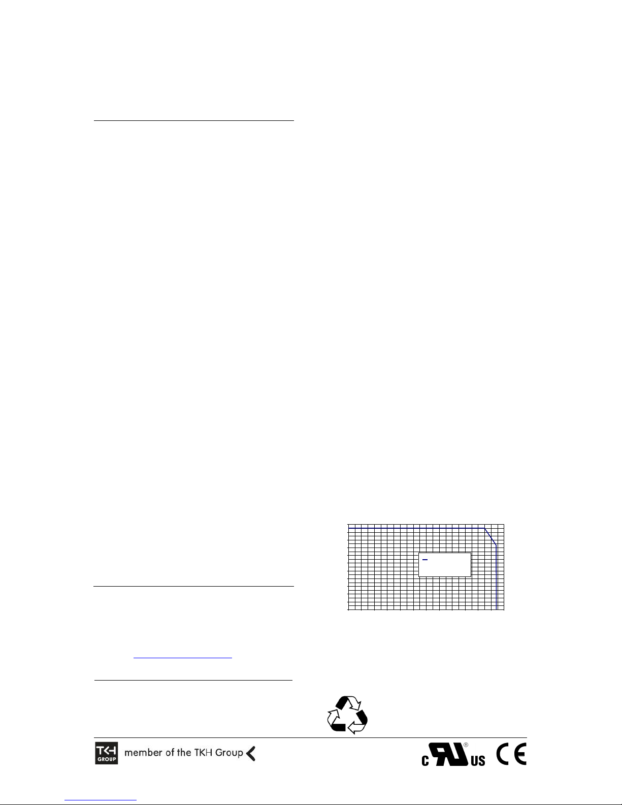
Figure 5. Power loading of the power supply cabinet
11 slots loaded with 9W modules: Max. ambient 65°C
11 slots loaded with 6W modules: Max. ambient 74°C
12. Product disposal
Recycling
This product contains valuable materials which
qualify for recycling. In the interest of protecting
the natural environment, properly recycling the
product at the end of its service life is imperative.
MC10-11 Power supply - Output Power Derating
0
10
20
30
40
50
60
70
80
90
100
110
-40 -30 -20 -10 0 10 20 30 40 50 60 70 80
Ambient Temperature [°C]
Total output power [W]
Total output power
+15V and -15V load
combined
Table of contents
Popular Power Supply manuals by other brands

Antec
Antec NeoPower 650 Blue specification

Superior Electric
Superior Electric STABILINE Installation, operation and maintenance manual

CAB
CAB Battery Pack 2 EOS1 Operator's manual

LenelS2
LenelS2 LNL-400XA quick reference

OSAKA VACUUM
OSAKA VACUUM TC163H Operation manual

Extron electronics
Extron electronics P/S 150 user guide


