Siro ERBS25LE Series User manual
Battery Motor – Radio Drive
ERBS25LE – Series
Compatible with:
Control Station SI7002
Remote Controller SIS1600, SIS1602, SIS1605
Solar Panel SI1288H
Sun Sensor SIS1187
05-2020

1
1. General safety guidelines
Notes on the product
Check the drive for intactness. Do not use the product if you discover any damage.
In this case, contact the point of sale.
Only use the drive to open and close suitable hangings.
Read this manual completely before starting the installation.
Make sure that the roller blind’s tube, in which you intend to use the drive, is
undamaged.
Check that the blind can be opened and closed smoothly.
Replace damaged parts if you find any defects.
Inform all persons in safe use of the controls and the drive.
Observe the blind during the operation and keep people away until the blind is
fully opened or closed.
Do not allow children to play with the control unit.
2. Installation of the motor
Do not hit the motor with hard objects – not even to push it into the winding shaft.
This can cause damage to the drive and roller blind’s shaft.
Avoid installing the tubular motor in damp places or places where it comes into
contact with water.
Installation
Place the tubular motor into the roller blind’s shaft.
The driver and adapter must be completely recessed into the winding shaft. The adapter must
be first pushed into the groove provided for this purpose on the crown of the motor head.
The drive head of the motor can be installed on the right or left side.
During installation, make sure that the drive head can be reached at any time after installation
in order to charge the drive via the external power supply.
2
3. Electrical connection
The distance between the drive and the transmitter should be at least 300 mm.
The distance between the two radio receivers should be at least 500 mm.
Strong, local transmitters (e.g. radio headphones) whose transmission frequency is identical
to the control (433MHz) can influence the function.
It is recommended to fully charge the drive before the initial installation using the included
micro USB charging cable (ca 2 hours). Only then will the motor reach full power.
The engine can also be operated and programmed during charging.
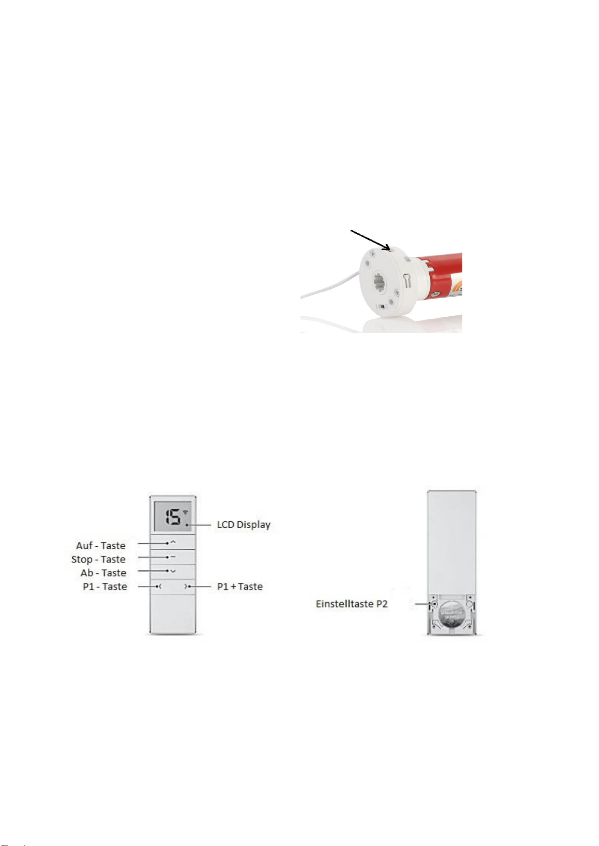
Mains connection at motor head:
4. Programming of the remote control (radio) transmitters
4.1 Check the connection between the engine and transmitter
1. First set the switch on the motor head from 0 to 1.
2. Test the connection between the handheld transmitter (remote controller) and the motor by
pressing the up or down button to move the drive up or down. If the connection exists,
please go directly to point 4.3.
3. If the motor does not move, you must first establish the connection between the motor and
the transmitter.
Important: For all programming, please only use the left P2 button as shown.

3
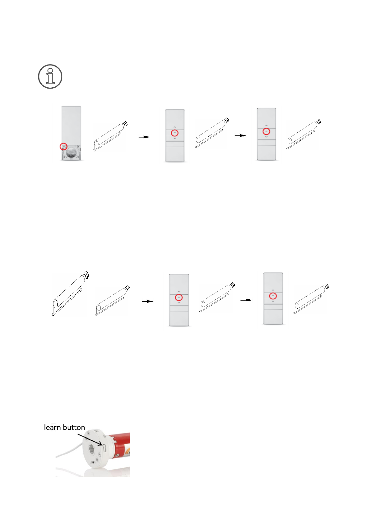
4.2 Establishing the connection between the motor and the remote controller
Establish connection:
The connection from the drive to the remote controller is thus established. You can now
control the drive by pressing the up and down buttons on the remote controller.
Initially, the drive moves only step by step when the up/down button is pressed briefly.
If you press the button for a long time, the drive then moves permanently. Once the end
positions have been set, the mode of operation then changes automatically to permanent
mode.
Delete connection:
If the end positions are already set (important!), the connection between motor and remote
controller can be deleted by completing the same operations as for Establish connection.
4.3 Check and change the direction of rotation of the drive
If the direction of rotation is reversed, the following explains how to change it.
Important: Please note that this change must be made before setting the end positions.
2. Specify a channel. Press and hold
the stop button on the remote
controller, up to 10 seconds, until
the drive responds with two
up/down movements and three
beeps.
1. Press and hold the learn button on the
motor head with an object until the drive
reacts only once (usually after 3 seconds) with
a short up/down movement and a beep.
Release the learn button immediately.
Keep the up and down buttons pressed
simultaneously until the drive reacts with
short up/down movements. Release the
buttons again. This changes the direction
of rotation of the motor.

4
5. Setting the end positions
You need to define the upper and lower end positions, when reaching these, the
drive switches off automatically. To do this, the drive system must be fully inserted.
You can choose whether to set the lower or upper end position first.
The time between each button combination should not exceed 6 seconds.
Otherwise, the setting status is aborted.
With some roller blind fabrics, enormous temperature fluctuations cause the fabric
length to change. Depending on the fabric and overall length, in extreme cases, there
can be a shortening in cold weathers and a lengthening at high temperatures, which
can even be in the centimetre range. Especially for cassette systems, it is necessary
not to parameterize the upper end position up to the stop but to leave at least 1 cm
clearance!
Setting the end position: In the following, the settings of the end positions are described,
starting with the upper end point. You can also start with the lower end point here.
Thus, the upper end position is set. The setting of the lower end position is analogous by
replacing the up button with the down button. If both end positions are set, the drive will
automatically stop at the respective end positions during operations.
Please note that saving the setting is only effective if both end positions are set.
Changing the end position (option): The following shows how to change the upper end position.
Thus, the upper end position is changed. You can also change the lower end position in the
same way by replacing the up button with the down button.
1. Press the up button and let the drive
move upwards. Press the stop button
when the motor has reached the desired
upper end position.
2. Press and hold the up and stop
buttons simultaneously until the motor
reacts with two up/down movements and
three beeps. Release the buttons again.
1. Press and hold the up and
stop buttons simultaneously
until the drive reacts with a
singe up/down movement and
a long beep. Release the
buttons again.
2. Then move the
drive to the new
desired end position
using the up and
down buttons.
3. Press and hold the up
and stop buttons
simultaneously again until
the drive reacts with two
up/down movements and
three beeps. Release the
buttons.
5
6. Setting a desired middle position (optional)
You can set a middle position of your choice as an option.
The middle position can only be set after the two end positions have been set.
Setting the desired middle position:
The middle position is now set. You can move your drive to this position by pressing and holding
the stop button.
Deleting the middle position:
The middle position is hereby deleted.
7. Reset to factory settings
Press and hold the learn button on the motor
head with an object until the drive reacts only
4 times with a short up/down movement and
4 beeps. Release the learn button again. The
motor is now set to the factory settings. All
previous connections and settings are deleted.
1. Move the drive to the
desired middle position.
Press the P2 button
once. The drive confirms
with an up/down
movement and a beep.
2. Then press the stop
button once. The drive
confirms with an up/down
movement and a beep.
3. Press the stop
button again. The
drive confirms with two
up/down movements
and three beeps.
1. Move the drive to the
middle position. Press the
P2 button once. The
drive confirms with an
up/down movement and a
beep.
2. Then press the stop
button once. The drive
confirms with an
up/down movement and
a beep.
3. Press the stop
button again. The
drive confirms with one
up/down movement
and a long beep.

6
8. Technical data
Technical data
Power supply:
USB DC 5V 2A
Protection class:
IP22
Operating temperature:
0°C to +50°C
Definition
Diameter
D
(mm)
Length
L
(mm)
Torque
(Nm)
Rotational
speed
(U/min)
Power
input
(mA)
Weight
(g)
ERBS25LE
26
490
1,1
28
940
435
9. Bug fixing
Problem
Possible cause
Solution
Drive does not run
Battery weak
Charge the drive via the mains
connection on the motor head with
the charger.
Remote controller without
function
Change to a new battery.
Transmitter is not set up
Establish the connection between the
motor and the transmitter (see 4.2).
Drive is very slow,
even with charged
battery
Incorrect installation
Make sure that the shaft, materials
and drive can move freely.
Overloading
Check the loaded weight.
Drive stops in-
between both end
positions
Adapter or roller capsule
not positioned correctly
Check that the adapter is correctly
seated on the groove provided in the
crown and, if necessary, screw the
roller capsule into the shaft with a
locking screw.
The end position
changes marginally
Fabric changes due to
temperature differences
Reset end position (see 5).
10. Warranty conditions
SIRO Antriebs- und Steuerungstechnik offers a 2-year warranty on new drives that have been
professionally installed and properly operated in accordance with the installation instructions.
The warranty covers all design faults, material defects and manufacturing faults.
Any defects occurring within the warranty period will be remedied by SIRO free of charge by
supplying an equivalent or new product. Replacement delivery for warranty reasons does not
result in general extensions of the original warranty period.
Any claims for compensation beyond this are excluded.
Table of contents
Other Siro DC Drive manuals


Popular DC Drive manuals by other brands

KB Electronics
KB Electronics PENTA KB POWER KBRG-225D Installation and operating instructions

Powtran
Powtran PI9000 series quick guide

SOMFY
SOMFY sonesse 30 rts installation guide

Allen-Bradley
Allen-Bradley Series B Service manual

ABB
ABB ACS320 series Supplemental manual

FnL
FnL CRD Series Quick installation guide

YASKAWA
YASKAWA SI-EN3 installation manual

Shihlin
Shihlin SS2 Series installation guide

Wavelength Electronics
Wavelength Electronics QCL OEM Series DATASHEET AND OPERATING GUIDE

Beckhoff
Beckhoff ELX Series Documentation

Lenze
Lenze L-force 8400 HighLine C Push Through Series Mounting instructions

ABB
ABB ACS880 Series user manual


