SiMUaA
®
Sew Reach Introduction
CONTENTS
1. SPECIFICATIONS .........................................................................................................
05
2.
PREPARATION
OF
THE
SEWING
MACHINE
......................
..
.............................
..
.......
05
2·1
. Installation.......................................................................................................................................
05
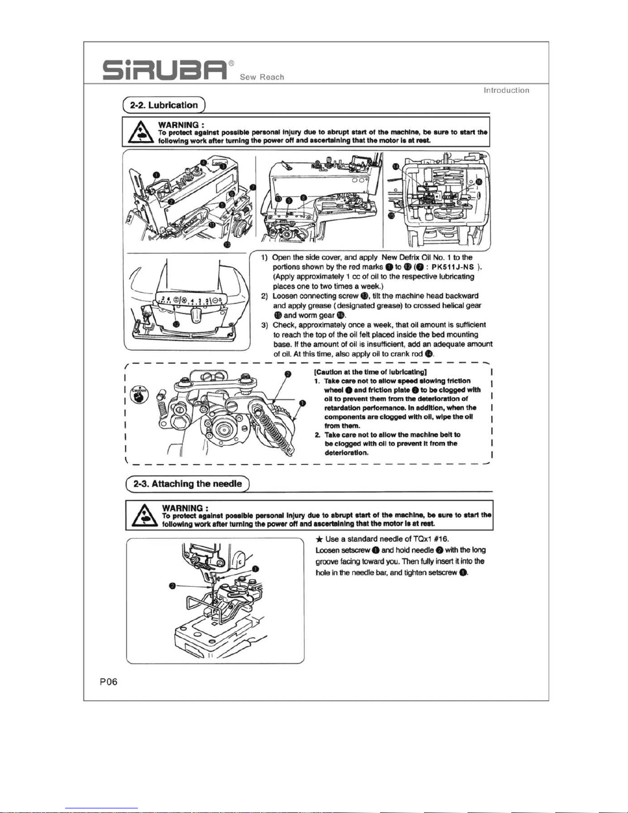
2·2. Lubrication.......................................................................................................................................
06
2-3. Attaching
the
needle.......................................................................................................................
06
2-4. Attaching
the
needle
bar
cover
......................................................................................................
07
2-5. Attaching the button
tray
assembly..............................................................................................
07
2-6. Threading
the
machine...................................................................................................................
07
3. ADJUSTMENT
OF
THE
SAWING
MACHINE ..............
..
...............................................
08
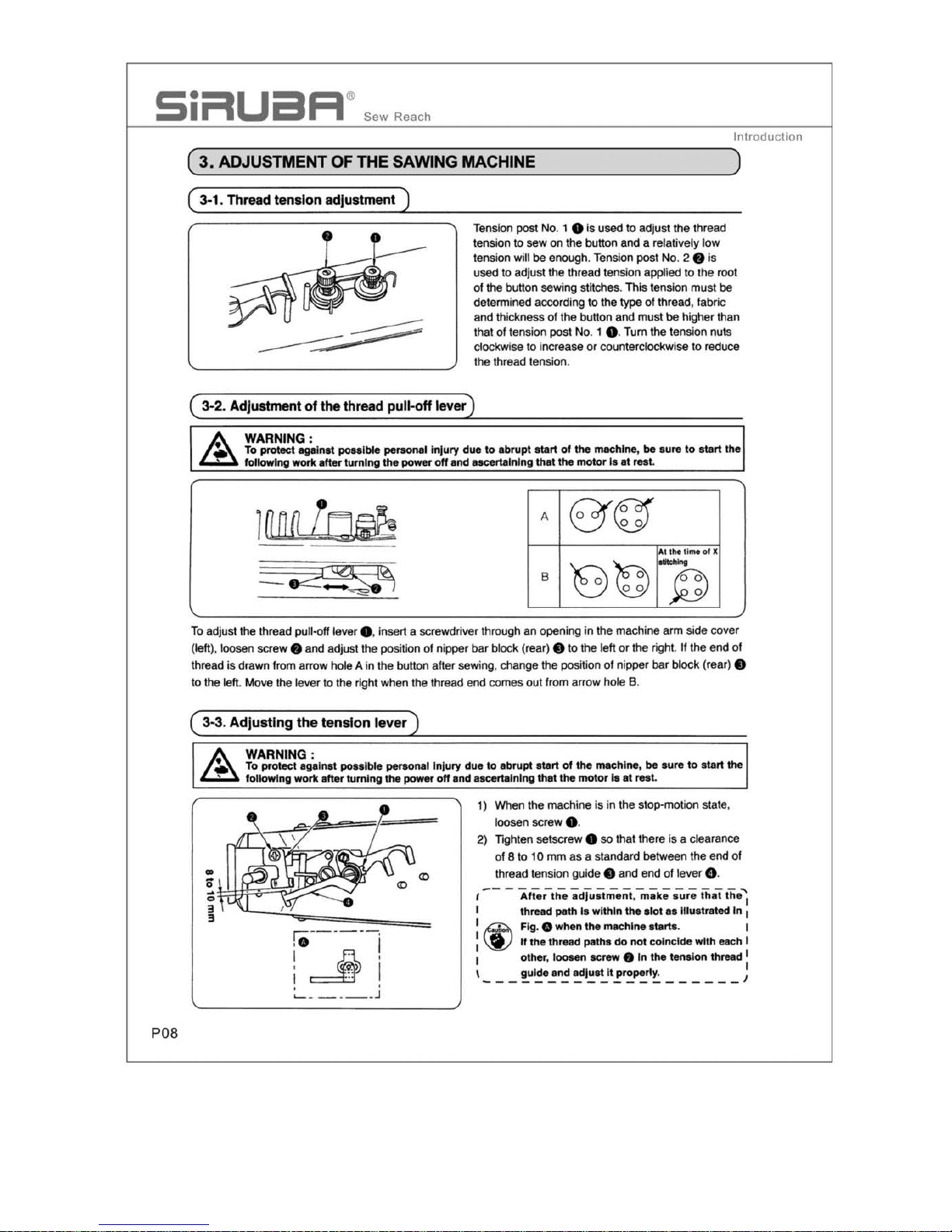
3·1. Thread tension adjustment.....................................................................................................................
08
3-2. Adjustment
of
thethread pull-offlever.................................
..
.................................................._..........
08
3-3. Adjusting
the
tension lever............................................................................................................
08
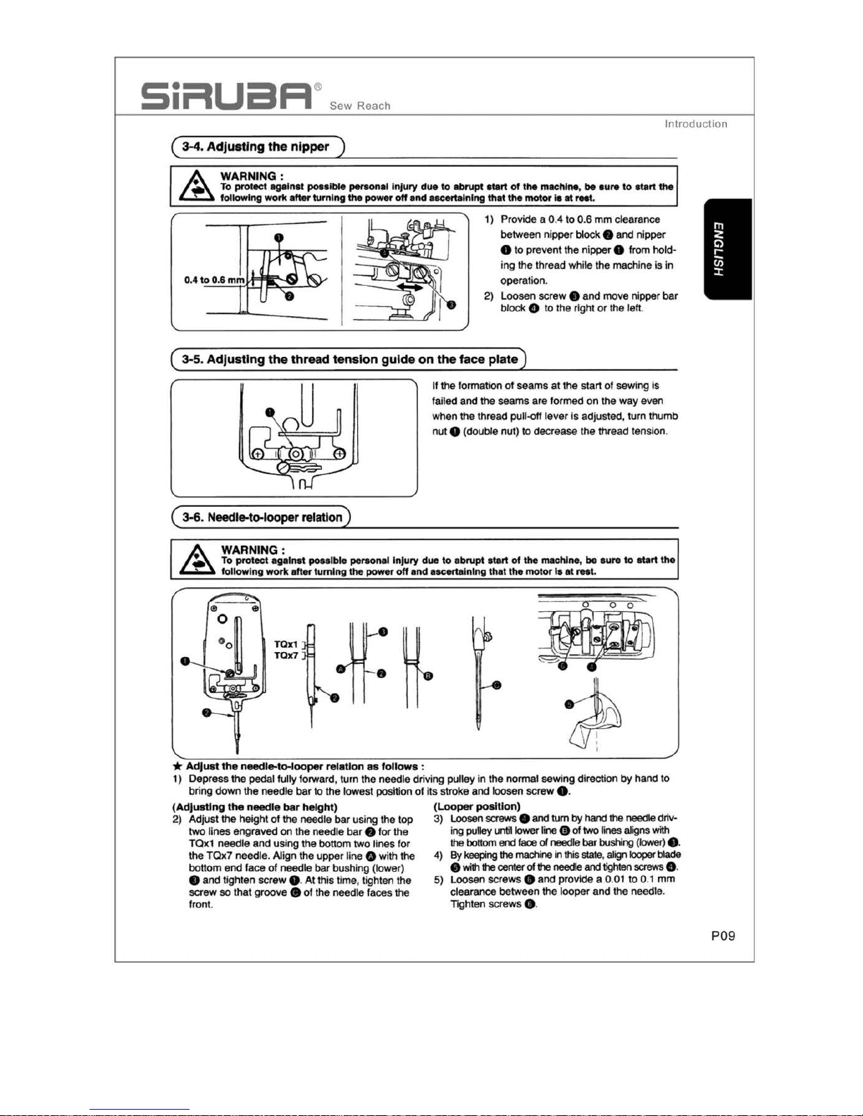
3-4. Adjusting
the
nipper.......................................................................................................................
09
3-5. Adjusting
the
thread tension
guide
on
the
face
plate
..................................................................
09
3-6.
Needle-to-looper
relation............................................................................................
..
...................................O9
3-7. Po
sition
of
the needle
guide
.........................................................................................................
..
10
3-8. Height
of
the button
clamp
............................................................................................................. 10
3·9. Work pressing force........................................................................................................................10
3-10. Adjustment
of
the
button clamp
stop
lever..................................................................................1O
3-11.
Timing
of
thread tension release..............................................................................................
...
11
3-12.Setting
for
2-or 4-hole
buttons
............................................................................
...
..................... 11
3-13. Settinga
number
of
stitches
.......................................................................................................
..
12
3-14.
Adjusting
the
position
of
the stop-motlon.................................................................................
..
12
3-15. Automatic thread
trimmer
...........................................................................................................
..
13
(
1)
Adjusting the position of
the
moving knife
....
............................................................................... 13
3-16. Clearance
between
the
button clamp
lifting
lever
and
the
adjusting screw ............................
13
3-17. How
to
set
the
L-shaped
lifting
rod
...............
..
..............................................................-.............
13
3-18.
Knot-tying
mechanisms
..............................................................................
..
................................
14
(1)
Adjusting the knot•tying connecting plate....................................................................................
14
(2)
Adjusting
the
knot-t
ying
arm
stopper...................................................................
....
..
......
..
..........
14
(3)
Adjusting
the
knot-tying notch...........................................
..
............................
..
....
..
...
.......
..
.........
14
(
4)
Changeover
of
with
/without knot-ty
ing
..................
..
...
....................
....
.
....
....
..
...............................
15
4.
MAINTENANCE
, SUBCLASS
MODELS
AND
ATTACHMENTS
.......
..
.....................
..
..
15
4-1.
How
to
connect
the
metal
fittings ofthe belt ...........................
..
...................................................
15
4-2
. Subclass models ..........................................................................................................................
..
.15
4-3.
Attachments
..........................................................................
..
..........................................................
16
(1)
Attachments for shank buttons
(Pearl
buttons)
(2033) .............................
..
.................................
17
(2)Attachment for the first process of
wrapped-around
buttons (2041)......
....
..
.........
....
...................17
(3)
Attachment for the
second
process of
wrapped-around
buttons (2035)....................................
..
18
(4)
Attachment for snaps (2037).............
..
.........................................................................................
18
(5)
Attachment for metal buttons (2038)................................................................
..
..........................
19
4-4
. Motorpulley
and
belt
............................................................................................................
..
.........
19
5.
TROUBLES
AND
CORRECTIVE
MEASURES
...................................
..
......
..
..........
......
20
P04