Siruba DT8200 Series User manual

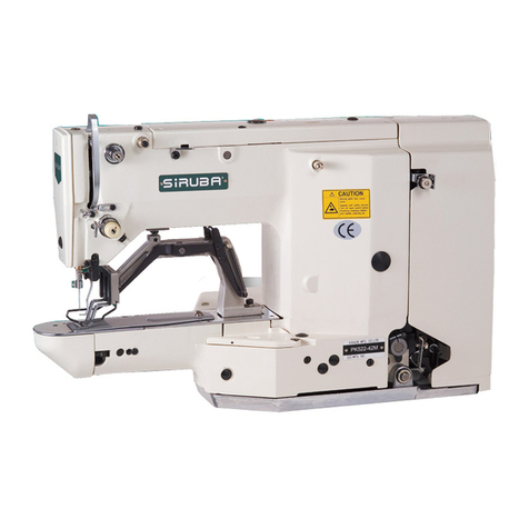
Siruba DT8200 series
Contents
1.
Installation Introduction.................................................................... 1
1.1
Product specifications..................................................................... 1
1.2
Interface connection ...................................................................... 1
2
Operation Panel Instruction.............................................................. 4
2.1
Operation panel display instruction ............................................... 4
2.2
The operation panel keysof description… .....................................5
3
System parameter setting................................................................. 9
3.1
Technician mode........................................................................... 9
3.2
Administrator mode .....................................................................14
3.3
Monitoring Mode..........................................................................20
3.4
Safety switch warning mode........................................................20
3.5
False alarm mode........................................................................21
4
Special function operating instructions........................................22
4.1
Upper stop position adjust...........................................................22
4.2
A key recovery machine manufacturersparameter value ...........23
4.3
Pedal sensitivity adjustment ........................................................23
4.4
Electromagnet performance adjustment......................................24
4.5
Start/ end back tacking sewing mode set....................................25
4.6
Start/ end back tacking sewing and Four-segment sewing is set long
needle................................................................................................ 26
4.7
H-70 operating panel count needle number / piece number function
27
i
Siruba DT8200 series
1. Installation Introduction
1.1
Product specifications
Product Type: AHU58A-55;AHD58A-55;Supply Voltage: AC 220 ± 20% V;
Power frequency: 50Hz/60Hz; Maximum output power: 550W;
1.2
Interface connection
The foot pedal and the head of each connecting plug into the socket on the
corresponding controller behind, each socket name as shown in Figure 1-2.Attached,
please check whether the plug is inserted.
1
Safety Instruction
·Please read this manual carefully, also with related manual for the
machinery before use the controller.
·For installing and operating the controller properly and safely, qualified
personnel are required.
·Please try to stay away from arc welding equipment, in order to avoid
electromagnetic interference and malfunction of thecontroller.
·Keep in room bellow 45° and above 0°
·Do not humidity below 30% or above 95% or dew and mist ofplaces.
·Install the control box and other components, turn off the power and unplug
the power cord.
·Toprevent interference or leakage accidents, please do the ground work,
the power cord ground wire must be securely connected to an effective way
to earth.
·All parts for the repair provided by the Company or approved beforeuse.
·Performing any maintenance action, you must turn off the power and unplug
the power cord. There are dangerous high voltage control box, you must
turn the power off after one minute before opening the controlbox.
·This manual marked with the symbol of the Department of Safety
Precautions must be aware of and strictly adhered to, so as not to cause
unnecessary damage.

Siruba DT8200 series
Fig.1-1 AS series Control Box
①:the motor power supply socket; ②: the pedal socket; ③:the motor encoder socket;
④:the operation panel switch socket socket;⑤:the turn table;⑥:the automatic
electromagnet socket; ⑦:the presser foot lifting electromagnet socket; ⑧:the head
lamp socket (black); ⑨:the external synchronizer socket.
⑨Synchronizer
①Motor Power
② pedal
③Encoder
④Operation panel
⑤Safety SW.
⑥Machine head solenoid
⑦Press foot lifter
⑧Lamp
Fig.1-2 AH series control box outlet backplane
2
:The use of the normal force are not inserted into the plug and socket, please check whether the
matching, direction or needle insertion direction is correct! Lighting interface and presser foot lifting
electromagnet interface is a 1*2 interface, head lamp interface using black interface, please pay attention to
the distinction between.

Siruba DT8200 series
Fig.1-3 Controller interface definition
■
1.3 Power Connection and Grounding basic parameters
Please electrical engineer must do construction to the system grounding
engineering. Electricity and put into use, must ensure that the power supply socket AC
input has been safe and reliable grounding. System ground is yellow-green line, the
line must be connected to the power grid safe reliable grounding protection, to ensure
the safe use, and can prevent the abnormal situation.
3
:All the power line, signal line, ground wire connection not by other objects or excessive
pressure to distort, in order to ensure the safe use!

Siruba DT8200 series
2
Operation Panel Instruction
2.1
Operation panel display instruction
According to the operating condition of the system, LCD module of operation panel
will display the sewing patterns, various parameters, front / back fixed seam to set the
current, and the presser foot, stop needle position, trimming thread, slow up the joint
character of the LCD.
Fig.2-1 H-70 appearance
Fig.2-2 H-70 LCD screen icon
Table 2-1LCD Icon Display Description
Index
Icon
Description
Index
Icon
Description
Automatic trimming
W sewing
Soft-start function
Multi-segment sewing
start back tacking
Multi-seam trigger function
End back tacking
Automatic test
Sewing segments
index
Clamp function
4

Siruba DT8200 series
Numeric character
display (pin number /
parameter)
Four –segment sewing
Foot lifter after
trimming
Count needle number
Middle stop foot lifter
Count piece number
Intermediate stops
down stop position
Count display
Intermediate stops
up stop position
Speed mark
needle and piece
number of base line
2.2
The operation panel keys of description
Table 2-2 Each key function introduction
No
Appearance
Name
Description
1
Function key
The key is parameters confirm key, and back to the previous menu
until the operator sewing mode state. In addition, work with other
key to set a higher level of theparameter.
2
Start back tacking key
It is called start back tacking function selection keys, every
effective press the key once, system will be in accordance with the
11B parameter set none and single start back 、, double
start back tacking , four start back tacking , LCD icon
is lit at the same time. Show is start back tacking
interface, Select the key and the key can set
needle(C、D) default range 1~F corresponds to the 1~15 pin.
5

Siruba DT8200 series
No
Appearance
Name
Description
3
End back tacking key
It is called end back tacking function selection keys, every effective
press the key once, system will be in accordance with the 11B
parameter set none and single end back tacking , double end
backtacking , four end back , LCD icon is lit at the
same time. Show is end back tacking interface, Select the
corresponding
key and the key can set needle(C 、D) default
range 1~F corresponds to the 1~15 pin.
4
Free sewing mode key
Press this key, the system into free sewing mode. LCD icon
is lit, step on the pedal to start sewing.
5
W sewing mode key
Press this key, system into w sewing mode, LCD
is lit,
shown is w sewing interface, Select the
corresponding
key and the key can set needle(A、B、D)
default range 1~F corresponds to the 1~15 pin.
6
Multi-segment sewing
mode key
It is called constant sewing, you press the key, the system enters
to the multi segment sewing mode, LCD icon is lit, shown
is multi –segment sewing interface, is
total segment, key and the key to adjusting, the default
maximum 24 segments, as the current setting section,
as the sewing needle number of the current section, they are
used
key and the key toadjusting.
Press this key, system into the four segment sewing mode, LCD
7
Four-segment sewing
mode key
icon is lit, shown is four-segment sewing interface,
Select the key and the key can set needle( E,
F, G, H) default range 1~F corresponds to the 1~15 pin.
6

Siruba DT8200 series
No
Appearance
Name
Description
8
Soft start key
Press this key, LCD icon is lit, show soft start function
effectively, then press the icon is off, indicates close soft start
function.
9
Clamp string key
Press this key, LCD icon is lit, show clamp function
effectively, then press the icon is off, indicates close clamp
function.
10
Stop position key
When sewing midway stop, system upper / lower needle stop
position by pressing the
is lit, that is up needle stop
position, then press the key, is lit, show down needle stop.
the sewing complete trimming, the system will stop up needle
position. Note: the H-43 panel without the key, the key
+combination to achieve the function.
11
Stitch compensation
key
In the free sewing midway stop or multi segment sewing section
stop, press the key can realize stitch compensate function. One
shot the button to fill half needle, press a long time to fill a needle,
keep the continuous stitch compensate.
12
Trimming key
Press this key, LCD icon is lit, indicate that the automatic
trimming function effectively, then press the icon is off, indicates
close trimming function.
13
Press foot lifting key
Each press once, system presser foot model will not automatically
presser foot, trimming back automatic presser foot ,
sewing to automatic presser foot ,sewing end and stop
press foot lifting four modes, corresponding LCD icon is lit up at
the same time
7

Siruba DT8200 series
No
Appearance
Name
Description
14
One-Shot-Sewing key
In the multi segment sewing mode, press the key, LCD icon is
lit
, suggesting that trigger mode effectively, the pedal can be
accomplished once the current period of setting needle sewing;
then click the icon out, show that multi segment joint triggered off.
15
Lamp
H-43 and H-70 panel support machine headlight dimming function,
in order to press the key, can get close and from dark to bright four
stage light modulation effect.
16
Custom functions
key
Custom extension function keys, and according to the situation
can work with other key combination function
17
Speed increase and
decrease key
The highest speed of system can be fast adjustment. In the multi
segment sewing mode, also as the total segments of the adjust
button. In addition, the parameter setting, can be used as keys
corresponding to the adjustment parameter.
18
Parametric increase
and decrease key
Adjust the parameter values increase and decrease
19
Switch key
Fast switching operation, the retention, not being used (H-43 panel
without this key).
20
Counting switch key
Counting switch meter needle number model and the piece
number model (H-43 panel without this key).
21
Count zero clearing
key
Count needle mode and piece mode current count the clear button
(H-43 panel without this key).
8

Siruba DT8200 series
3
System parameter setting
3.1
Technician mode
1
、
Press
key and key can modify the technician parameter table.
2、The LCD will display .Type the password for the technician, the initial password is 0 0
0 0,press the corresponding key and key can change the password value;
3
、
key,If the password is correct, enter into the technician parameter setting mode,shown
,
4 、Press the corresponding to key and the key, select the parameter and change the
corresponding parameter.
5
、
key, exit parameter setting mode, return to sewing mode.
NO.
Range
Default
Description
Comment
100
100~800
200
Start sewing speed
Speed
101
200~5000
3500
Maximum sewing speed
102
200~5000
3000
Maximum constant sewing speed
103
200-5000
3000
Maximum manual back tacking speed
104
100- 600
200
Manual compensation stitch speed
105
100~500
250
Trimming speed
106
0-1
0
Soft tart set up 0 :soft star only after trimming 1 both stop and Tr
107
1~99
2
Soft start stitch number
108
100~800
200
Soft start speed
110
200~2200
1800
Start back tacking speed
Back tacking
Para.
111
200~2200
1800
End back tacking speed
112
200~2200
1800
W-type sewing speed
113
1~70
24
Start back tacking, No.1 stitch compensation profile A
114
1~70
20
Start back tacking, No.2 stitch compensation profile B
115
1~70
24
End back tacking, No.1 stitch compensation profile C
116
1~70
20
End back tacking, No.2 stitch compensation profile D
11A
10~359
170
Stitch compensation reference angle(optimum actuation angle of
backstitch electromagnet)
9

Siruba DT8200 series
11B
0-4
0
Start and end back tacking type (CD and AB)
0:B->AB->ABAB->none
1:B->none
2
:
B->AB->none
3:AB->none
4:AB->ABAB->none
11C
0000-
0
Corresponding to A/B/C/D pins of ten bit, start and end back
tacking interface under the A/B/C/D digits together constitute the
two digit pin number, each section of pin number 1~99 needle.
11D
0000-
0
Corresponding to E/F/G/H pins of ten bit, start and end back
tacking interface under the E/F/G/H digits together constitute the
two digit pin number, each section of pin number 1~99 needle.
130
0
/
1
/
2
/
3
2
Pedal speed-control profile mode:
0:Auto linear ramp (auto calculation according to max. speed)
1:Two segment liner Curve.
2:Power law curve
3:S-type curve
Pedal
Para.
131
200~4000
3000
Sub-Para. Of two-stage speed control: mid-turning-point speed
RPM (two-stage ramp turning point speed)
132
0~1024
800
Sub-para. Of two-stage speed control ramp: Pedal analog value
of mid-turning-point (in 138 to 139 parameters)
133
1
/
2
1
Sub-para. Of power speed control curve:
1: Square 2:Radiation
134
0~1024
0
Trimming pedal-position
Figure 4-1shows the
specific setting method.
135
0~1024
300
Foot lifting pedal-position
0~1024
4 0
Pedal back to Mid position
137
0~1024
480
Pedal start running position
138
0~1024
580
Pedal low speed running position
139
0~1024
2
Pedal max. Analog value
13A
0~800
100
Pedal foot lifting confirming time
10

Siruba DT8200 series
13C
0
/
1
1
Foot lifting position, foot lifting function selection:
0: without 1:with
13E
1~800
0
Trimming after, foot lifting delay time(clamp)
140
0
/
1
1
Run to up needle position after Power on:
0: no action
1: action
141
0
/
1
1
Automatically reinforcing functions chose :
(the machine head is not automatically reinforcing functions, the
best way is prohibit)
0:prohibit 1:allow
142
0
/
1
0
Function mode selection when manually push back tacking
0:Jukimode. During sewing or stop sewing both have this action.
1:Brother mode. Only acts during sewing.
143
0
/
1
/
2
/
3
0
Special operation mode:
0: Operator selection
1: Simply sewing mode
2: Motor initial angle measurement (not necessary to remove the
belt)
3: Ratio mode calculation (synchronize encoder is necessary and
belt can not be removed)
Customize
Set up
144
0~31
0
Motor torque increase function in low speed on & off:
0: Normal functions
1-31: low speed torque increase level
148
0
/
1
/
2
0
Fill needle mode:
0: the time control;
1:fill half needle;
2:fill a needle
The presser foot lowering speed slowed down: slow release
149
0
delay coefficient, bigger down more slowly
14A
0~10
0
Pedal acceleration curve filtering coefficient
150
1
~
100
1
Stitch counting proportion set up
151
1
~
1
Stitch counting value set up
11

Siruba DT8200 series
152
0
~
4
0
Stitch counting mode selection: 0: no counting
1: Counting up according to stitch number, after reaching set
value then restart.
2: Counting down according to stitch number, after reaching set
value then restart.
3: Counting up according to stitch number, after reaching set
value ,motor automatically stop, by the reset button set or the P
key on the panel to start counting again.
4: Counting down according to stitch number, after reaching set
value ,motor automatically stop, by the reset button set or the P
key on the panel to start counting again.
5: Counting up according to stitch number, after reaching set
value ,alarm, motor lock after trimming thread.
6: Counting down according to stitch number, after reaching set
value ,alarm, motor lock after trimming thread.
Count
Mode
153
1
~
100
1
Cunting piece proportion set up
154
1
~
1
Counting piece value set up
155
0
~
4
0
Trimming counting mode selection:
0: no counting
1: Counting up according to piece number, after reaching set
value then restart.
2: Counting down according to piece number, after reaching set
value then restart.
3: Counting up according to piece number, after reaching set
value, motor automatically stop, by the reset button set or the P
key on the panel to start counting again.
4: Counting down according to stitch number, after reaching set
value, motor automatically stop, by the reset button set or the P
key on the panel to start counting again.
12

Siruba DT8200 series
P
156
0
~
0
Corresponding to 1/2/3/4, an electromagnet chopper duty time
selection (0 in MS, 1 in 0.1ms)
157
0
~
0
Corresponding to 5/6/7/8, an electromagnet chopper duty time
selection (0 in MS, 1 in 0.1ms)
158
0
~
1
0
Counting adjustable switch (gauge needle number and piece
number (0) adjustable, 1 non adjustable)
161
0
/
1
/
2
Para. transmission method:
0: no action;
1: Para. Download (from operation panel to controller);
2: Para. Upload (from controller to operation panel).
Operation
162
1, 2
Recover to default parameter
163
1, 2
Save current para. As User custom para.(recoverable)
164
-
Password
165
-
Recovery controller factory parameters, and covering the head
factory parameter or user defined mechanical parameters. The
original parameters can not be restored.
Note: Such “16x "parameter to operate is saved, you need press key, about 3-5 seconds, it is saved.
13

Siruba DT8200 series
3.2
Administrator mode
1、Press key and key can modify the administrator parameter table.
2、The LCD will display .Type the password for the administrator, the initial password is
0 0 0 0,press the corresponding key and key can change the password value;
3、key,If the password is correct, enter into the administrator parameter setting mode,shown
,
4 、Press the corresponding key and key,select the parameter and change the corresponding
parameter.
5、key, exit parameter setting mode, return to sewing mode.
NO.
Range
Default
Description
Comment
200
0
/
1
/
2
0
Trimming motor operation mode selection:
0:lockstitch sewing machine
1:interlock machines(ordinary flat seaming shearing line: stop to
the needle position after the trimming)
2:The over-lock type: manual trimming
202
0
/
1
/
2
/
3
/
4
/
5
/
1
Trimming time sequence selection:
0: The parameter 203 set angle[TS] start trimming, until the
parameter 206 upper needle stop position is reached, then time
delay to [T2] set value.
1: The parameter 203 set angles [TS] start trimming, until the
parameter 204 set [TE] angle.
2: The parameter 203 set angle [TS] start trimming, time delay to
the parameter 206 set [T2] value.
Trimming
Mode
3: After lower needle stop position is reached, time delay to the
parameter 205 set value [T1] then start trimming, time delay to the
parameter 206 set value [T2].
14

Siruba DT8200 series
4: After upper needle stop position is reached, time delay to the
parameter 205 set value[T1] then start trimming, time delay to the
parameter 206 set value [T2], most applications are for interlock
machines.
5: find the needle position signal started first stop pin stop
tangent action. Tangent time delay [T2] and 205parameters of
the set time [T1] after the 206 parameter set.(most generally used
for car models, while T1 and T2 setting value most are set to 0)
6:203 parameters that are set at [TS] of the
tangent ,Toshiba first stop pin stop. Tangent
time delay [T2] and205 parameters of the set time [T1] after
the 206 parameter set.
203
5-
10
Trimming start angle TS (relate to down needle stop position
angle)
204
10-35
120
Trimming finish angle TE (relate to down needle stop position
angle, the value should be bigger than TS)
205
1-
10
Trimming start time delay T1(ms)
206
1-
120
Trimming finish time delay T2(ms)
20 A
10- 0
20
trimming force coefficient (motor force)
210
0
/
1
/
2
/
3
/
4
/
5
/
0
Thread slack electromagnet sequential selection:
0:211 parameter set point of [LS] after loose line, untilthe needle
position to delay 214 parameter set time [L2].
1:211 parameter set point of [LS] after loose line, until
the 212 parameter set angle [LE].
2:211 parameter set point of [LS]
after loose line, 214parameters set by the [L2] until the time delay.
3: bit signal delay [L1] set the time
to loose line, 214parameters set by the [L2] until the time delay.
15

Siruba DT8200 series
4: needle position signal delay [L1] set the time
to looseline, 214 parameters set by the [L2] until the time delay.
Under 5: bit signal started loose line first stop pin stop.Then the
delay parameter 213 set time [L1] after
the 214parameter set loose line time [L2].
6: 211 parameter set point of [LS] after loose line, first stop
pin stop. Then the delay parameter 213 set time [L1] after
the 214 parameter set loose line time [L2].
Thread
slack/
Thread
sweeping/
String
nipping
Mode
211
5-
25
Thread slack electromagnet start angle LS (relate to down needle
stop position angle)
212
10-35
350
Thread slack electromagnet finish angle LE (relate to down needle
stop position, the value should bigger than LS)
213
1-
1
Thread slack electromagnet start time delay T1(ms)
214
1
~
10
Thread slack electromagnet time delay T2(ms)afterupper needle
stop position is reached
215
0
/
1
1
Selection for wiper function
0: off 1:on
216
1
~
10
Thread wiping /Thread sweeping time delay ms
217
1
~
70
Thread wiping/Thread sweeping time delay ms
218
1
~
50
Thread wiping/Thread sweeping recover time ms
219
0
/
1
0
Thread nipping function selection
0: off 1: on
21 A
10-35
120
Thread nipping initial angle
21 B
11-35
318
Thread nipping finish angle
21 E
11-35
1
0
Lower angle after foot lifting when thread nipping
22 0
200
~
3
0
3
0
Stop position after trimming(can implement pull back function after
trimming)
16

Siruba DT8200 series
224
0/1/2/3
0
Emergency Stop Mode:
0: Turn off the emergency stop function
1: Emergency stop at any position
2: Emergency stop at upper needle stop position
3: Emergency stop at lower needle stop position
Stop
Mode
225
0
~
0
Continue stitch No. before emergency stop (according to different
set speed and stitch No., the actual value might be bigger)
226
0/1
0
Restart after emergency stop:
0: Can not be restart, it’s necessary to restart the power.
1: When the alarm is canceled, can be restarted.
231
0
/
1
0
Auto test mode selection:
0: With certainstitch number 1: With certain time
232
0
~
1000
300
Safety alarm confirming time ms (for flat sewing machine safety
tilting switch and overlock sewing machine safety knife protection
switch are same, use the same solution)
233
0
~
1000
50
Safety switch recover confirm time ms
234
0
/
1
0
Motor resolving direction:
1: C.C.W 0: C.W.
240
0
~
1000
Motor/machine ratio:0.001
(If ratio has been calculated automatically, the para. In the
controller might be different with HMI)
Machine
Para.
241
-
-
Retain
244
0
~
0
Adjustment angle of upper needle stop position (relate to angle
difference of upper needle stop position encoder)
243
0
~
175
Mech. Angle of lower needle stop position
244
0~800
200
Foot lifting release time delay (ms)
245
0
~
Torque increase initial angle of over thick material
246
0
~
57
Torque increase finish angle of over thick material
17

Siruba DT8200 series
247
0
~
2000
0
Oil refill time alarm (hour. 0: function deactivated)
248
0
~
4000
0
Oil alarm, stop operation time (hour. 0: function deactivated)
250
As
follows
1
No.1 input definition
Input
function
definition
25 1
1
No.1 active input level 0/1
25 2
0
No.2 input definition
253
0
No.2 active input level 0/1
254
0
No.3 input definition
255
0
No.3 active input level 0/1
256
0
No.4 input definition
257
0
No.4 active input level 0/1
250
-
25B
0:Disable 1:Manual back tacking 2:Safety switch 3:Emergency stop 4:Material side detection 5:Pedal
trimming input 6:Pedal foot lifting input 7:Stitch compensation 8:Front-end/rear-end back tacking reverse
9:Presser foot alternation lifting 10:Air-tight joint 11:Counter reset 12:OP input 13:Presser foot alternation
input 1 14:Presser foot alternation input 2 15:Needle lifting lock 16:Edge joint presser foot control input 17:
Double needle machine left input;18:Double needle machine right input;19:Deputy tension control input
260
As follows
1
No. 1 electromagnet output definition
Output
Definition
261
3
No. 2 electromagnet output definition
4
No. 3 electromagnet output definition
No. 4 electromagnet output definition
2
No. 5 electromagnet output definition
No. 6 electromagnet output definition
-
0:Output disable 1:Trimming 2:Thread wiping 3:Back stitch 4:Foot lifting 5:Thread slack 6:Thread nipping
7:Air sucking 8:Air blowing 9:Needle cooling 10: Presser foot alternation lifting 11: Air-tight joint 12:Back
tacking reverse hanging mode 13:Alternation lifting mode 14:Air-tight joint mode 15:OP output 16:Bottom
thread counter full condition 17:Trimming short thread head output 18: Edge joint presser foot control output
19:Double needle turn left needle bar actuation ;20:Double needle turn right needle bar actuation ;21:
Double needle turn left state 22:Double needle turn right state 23:Deputy tension control output;24:Deputy
tension control state
18

Siruba DT8200 series
270
1
~
500
50
No.1 electromagnet fully output time ms
No.1
Electrom
agnet
271
1
~
100
1
No.1 electromagnet chopping on time ms(Reserved)
272
1
~
100
1
No.1 electromagnet chopping off time ms(Reserved)
273
0
~
00
0
No.1 electromagnet protection time 100ms
274
1
~
500
70
No.2 electromagnet fully output time ms
275
1
~
100
1
No.2 electromagnet chopping on time ms(Reserved)
27
6
1
~
100
1
No.2 electromagnet chopping off time ms(Reserved)
277
0
~
00
0
No.2 electromagnet protection time 100ms
278
1
~
500
150
No.3 electromagnet fully output time ms
2 79
1
~
100
1
No.3 electromagnet chopping on time ms(Reserved)
27 A
1
~
100
1
No.3 electromagnet chopping off time ms(Reserved)
27 B
0
~
00
0
No.3 electromagnet protection time 100ms
27 C
1
~
500
100
No.4 electromagnet fully output time ms
27 D
1
~
100
1
No.4 electromagnet chopping on time ms(Reserved)
27 E
1
~
100
1
No.4 electromagnet chopping off time ms(Reserved)
27 F
0
~
00
0
No.4 electromagnet protection time 100ms
280
1
~
500
40
No.5 electromagnet fully output time ms
No.2
Electrom
agnet
281
1
~
100
0
No.5 electromagnet chopping on time ms(Reserved)
282
1
~
100
0
No.5 electromagnet chopping off time ms(Reserved)
283
0
~
00
0
No.5 electromagnet protection time 100ms
284
1
~
500
100
No.6 electromagnet fully output time ms
285
1
~
100
0
No.6 electromagnet chopping on time ms(Reserved)
286
1
~
100
0
No.6 electromagnet chopping off time ms(Reserved)
287
0
~
00
0
No.6 electromagnet protection time 100ms
19
Table of contents
Other Siruba Sewing Machine manuals

Siruba
Siruba 700KT User manual

Siruba
Siruba ASP-PTA100 User manual

Siruba
Siruba 747L User manual

Siruba
Siruba 700L-BKF1 User manual

Siruba
Siruba Siruba HSO-747 User manual

Siruba
Siruba 700DFT User manual

Siruba
Siruba ASP-BST100 User manual

Siruba
Siruba 700F User manual

Siruba
Siruba BH9820 User manual

Siruba
Siruba DL7200D-NM1 User manual

Siruba
Siruba C007K User manual

Siruba
Siruba BH780 Datasheet

Siruba
Siruba C007KD User manual

Siruba
Siruba C007K User manual

Siruba
Siruba ASP-JBL100 User manual

Siruba
Siruba ASP-EBJ100 User manual

Siruba
Siruba ASL-JBH200C User manual

Siruba
Siruba L818F-BM1 User manual

Siruba
Siruba LKS-1900AN User manual

Siruba
Siruba 700K/988 User manual