Sisis DART User manual

DART
INSTRUCTION MANUAL
SP20015_REV3
OCTOBER 2017
2
CERTIFICATE OF CONFORMITY
Variseeder 1300 CN Code: 84323011
Manufacturer:- Howardson Ltd, Howardson Works, Kirk Langley, Derby, DE6 4NJ. UK
Owner of Technical Document:- Mr I.D. Howard, Howardson Ltd, Howardson Works Kirk Langley, Derby, DE6 4NJ, UK
I the under signed Declare that these machines:-
Model: DART Measured Sound Power Level: 79dB Lwa Guaranteed Sound Power Level: 98dB Lwa
The reliability and quality of performance of the SISIS DART depends upon some simple care maintenance
carried out regularly. This manual has been prepared to allow the user to carry out all such work.
It is advisable to read the instructions carefully. Proper care and attention will enable the machine to give a continuous,
satisfactory, and reliable service. Failure to carry out regular lubrication and maintenance as outlined in this manual may
render any guarantee or warranty invalid.
In the case of any difficulty, or if further information or advice is required, our Service Department is always at your call. In
the interests of speed and accuracy of information please quote the serial numbers of the machine and engine when
making enquiries.
For the machine, this is to be found on a plate attached to the side frame. The engine number is stamped
on either the crank case or the gear casing facing towards the front of the machine. We suggest you write
the numbers on the front page of this book.
INTRODUCTION
SERIAL NUMBERS
Tested at:- Howardson Works test site September 2012
Complies with the applicable requirements of:-
- Machine Directive 2006/42/EC
- Noise Directive 2000/14/EC (annex VI Procerure 1)
Ian Howard
Managing Director
MACHINE SERIAL NUMBER
NOTE:- MAKE A NOTE OF THE SERIAL NUMBER OF YOUR MACHINE AND ALWAYS
QUOTE IT IN ANY COMMUNICATION WITH PERSONNEL AT DENNIS.
ENGINE SERIAL NUMBER
SP20015_REV3
OCTOBER 2017

3
CONTENTS
IMPORTANT SAFETY INTRODUCTIONS
TECHNICAL DATA
CAUTION:- READ THE INSTRUCTIONS. We want you to obtain the best performance from this
machine. If you have any difficulty in carrying out the following instructions please contact
your local SISIS dealer.
NEVER
•Carry out adjustments whilst the machine is running.
•Allow any unauthorised person to handle machines in any way at any time.
ALWAYS
•Read the operating instructions carefully and understand the controls before commencing work.
•Be extra careful to avoid spillage, when using petrol or diesel fuel. DANGER no smoking or naked flames.
•Use safety guards and make sure they are correctly in position. They are supplied for your protection.
•Before starting work always visually check machine for damage or wear to parts.
•Look behind before starting to reverse and watch out for children or pedestrians.
•Respect powered machines. Always keep hands and feet clear of moving parts and remember that tine cylinders or
drums can continue to rotate even after the power unit is switched off.
•Switch off the power before making adjustments or repairs and never lift or carry a machine whilst any parts are moving.
EYE PROTECTION
In dry, dust or windy conditions it may be necessary to wear eye protection to protect your eyes from flying debris.
FIRE HAZARD
Always clean the machine. Remove all debris from around the engine. Blocked engine cooling fins can cause the engine to
over heat.
Page
Declaration of Conformity...................................................................................................................................................... 2
Serial Numbers...................................................................................................................................................................... 2
Introduction............................................................................................................................................................................ 2
Technical Data....................................................................................................................................................................... 3
Important Safety Instructions...............................................................................................................................................3-4
Operating Instructions............................................................................................................................................................ 5
Maintenance …………………................................................................................................................................................. 6
Tines …………………………………………………………………………………………………………………………………..….7
Parts Listings.................................................................................................................................................................. P0-P9
MODEL DART
WIDTH (mm) 680
LENGTH (mm) 1550
HEIGHT (mm) 1180
ENGINE GX160
WEIGHT (Kg) 217
WORKING WIDTH (mm) 16” (430mm)
Wheels –Rear
Wheels –Front (2) 13 x 6.50-6 slick
(2) 260 x 85-3.00-4 ribbed
Hand Arm Vibration (𝑚/𝑠𝑒𝑐2) 9.5
Measured Sound Power Level (dB(A)) 80
Guaranteed Sound Power Level (dB(A)) 98
SP20015_REV3
OCTOBER 2017

4
IMPORTANT SAFETY INSTRUCTIONS
in order to operate the machine safely please follow these health and safety guidelines.
TRAINING
CAUTION -Read the instructions contained in this manual with care. If you are in any doubts ask
your employer or contact us direct at SISIS.
•Be familiar with the controls and the proper use of the equipment.
•Never allow children or people unfamiliar with these instructions to use the machine. Local regulations or insurance may
restrict the age of the operator.
•Never operate while people, especially children, or pets are nearby.
•Keep in mind that the operator or the user is responsible for accidents or hazards occurring to other people on their
property.
PREPERATION
•While operating always wear substantial footwear and long trousers. Do not operate the machine in bare foot or in open
sandals.
•Thoroughly inspect where the equipment is to be used and remove all stones, sticks, wire, bones and other foreign
objects
WARNING - petrol is highly flammable and will damage grass if spilt.
A. Store fuel in containers specifically designed for this purpose
B. Refuel outdoors and do not refuel whilst smoking.
C. Add fuel before starting the engine. Never remove the cap of the fuel tank or add petrol while the engine is running or
when the engine is hot.
D. If petrol is spilled do not attempt to start the engine but move the machine away from the area of spill and avoid creating
any sources of ignition until the vapours have dissipated.
•Replace damaged or faulty silencers
•Before using the machine always inspect the safety devices including the cut off switch and the blades for excessive wear
or damage. Replace if necessary.
OPERATION
•Do not operate in daylight or good artificial light.
•Operate only in daylight or good artificial light.
•Always be sure of your footing on slopes.
•Walk. Never run.
•Exercise extreme care on slopes when changing direction.
•Do not operate on excessively steep slopes.
•Use extreme caution when reversing or pulling the machine towards you.
•Stop the tines when transporting the machine.
•Never operate the machine with defective guards or shields or without the safety devices, for example without the
deflector plate or grass box in place.
•Do not change the engine governor settings or over speed the engine.
•Disengage all blades and drive clutches before starting.
•Start the engine carefully following the instructions with feet well away from the blades.
•Do not tilt the machine when starting the engine.
•Do not put hands or feet near or under moving parts.
•Never pick up or carry the machine while the engine is running.
SP20015_REV3
OCTOBER 2017
5
OPERATING INSTRUCTIONS
CAUTION –Please read these operating instructions carefully before commencing work.
We want you to obtain the best performance from this machine. If you have any difficulties in carrying out the following
instructions please contact SISIS direct or your local SISIS territory manager or SISIS dealer.
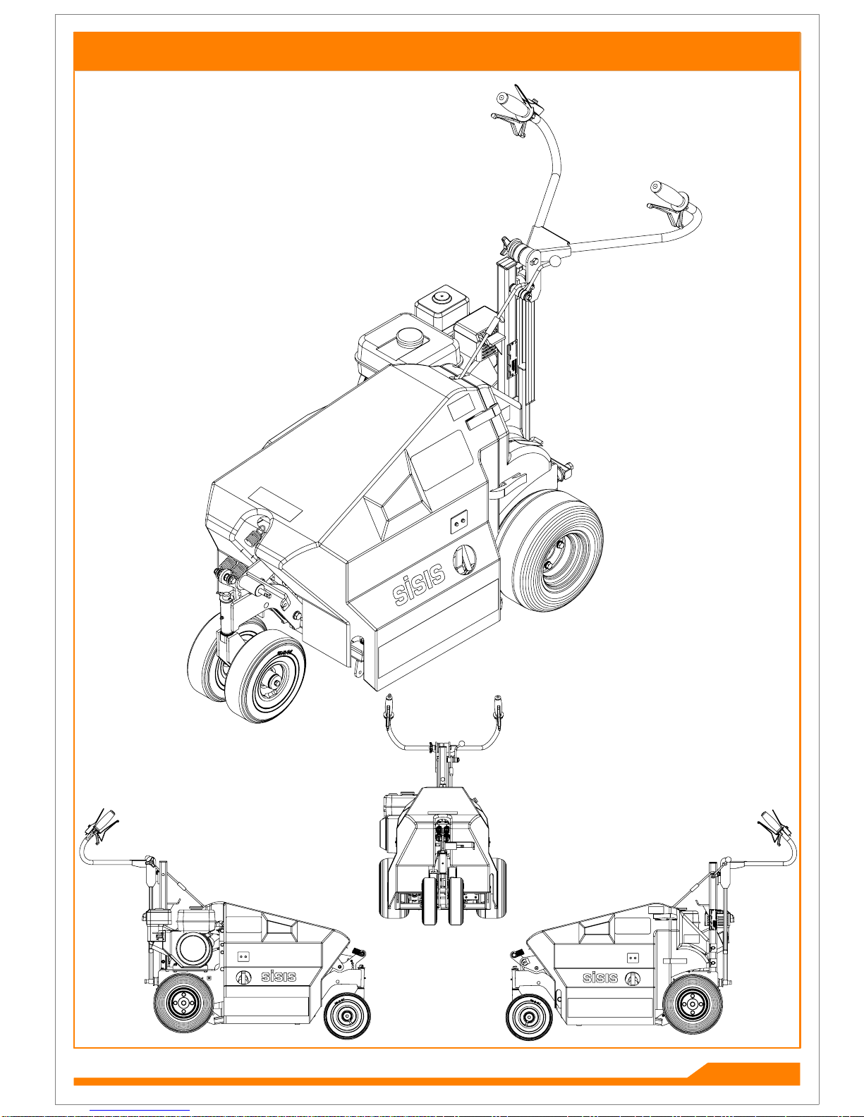
OPERATING PRINCIPLE
The SISIS DART is an engine driven vertical aerator for the use on fine turf areas such as bowling greens, tennis courts and all
areas of fine turf.
Offering clean vertical action of larger tractor mounted machines, the DART is easy to use and highly manoeuvrable. It has an
effective working width of 42cm and is powered by a Honda GX160 5.5hp engine. A wide range of tines are available (see
listings). Maximum working depth is 10cm (4ins).
All controls, including the balanced depth control are on the handles. The SISIS DART has been designed to require minimal
maintenance with sealed bearings throughout the mechanism and an easily removable cover.
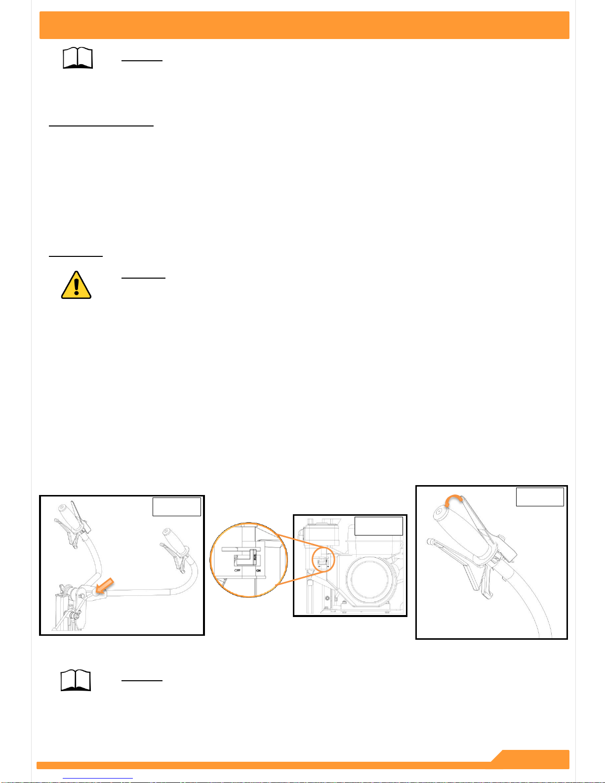
OPERATING
WARNING –The deadmans lever must be kept depressed whilst the engine is running or when starting
the engine. If the lever is released the engine will stop and will not restart until the lever is
depressed again.
1. Firstly ensure that the over centre lever to the tine drive is disengaged and that the tines are clear of the ground (see image
1)
2. Move the choke lever on the engine to start ( see image 2).
3. Ensure the isolator switch in the engine is on.
4. Depress the deadmans handle lever (see image 3)
5. Set the revs to the engine to approximately half way and pull the recoil starter.
6. When the engine is running smoothly, keeping the deadmans lever depressed, line up the machine for the first run,
7. Engage the over centre lever so that the tines are in drive.
8. Pull the drive clutch lever into operation and with the machine moving forwards pull the depth selection lever until the
desired depth is achieved. This is visible on the depth setting indicator.
9. When nearing the end of the run, lift the tines clear of the ground and take the tines out of drive with the tine drive over
centre lever.
10. Manoeuvre the machine into position for the next run and continue to proceed as previously described.
CAUTION - If the machine begins to bounce or the engine tries to stall, the ground is too hard for the
chosen depth. Select a shallower depth and the treat the ground at this depth until
conditions allow deeper penetration.
Image 1
Image 2
Image 3
SP20015_REV3
OCTOBER 2017

6
ROUTINE MAINTENACE
TO CHANGE A DRIVE BELT
Loosen the nuts on the bearing block and slide back until the belt may be slipped over the edge of the toothed pulley.
When fitting a new belt do not over tension. 10mm of deflection should be left at the centre of the new belt.
TIMING OF TOOTHED BELTS
When fitting a new belt it is important to rest timing.
Looking from the front of the machine, the right hand cam should be at 12 o’clock.
The left hand cam should be at 15 minutes past the hour. (See image below)
FOR THE ENGINE MAINTENANCE SEE MANUFACTURERS HAND BOOK WHICH IS SUPPLIED WITH THE MACHINE
Image 4
10mm
15 minutes past
12 o’clock
SP20015_REV3
OCTOBER 2017

TINES
1 2 3 4 5
NOTE Tine spacing = 50mm
The tines above are available for use with the dart. Maximum depth for all tines is 100mm.
1.) & 2.) Hollow Coring Tines –1 - D2107 (12.5mm Dia), 2 –F36447 (16mm Dia)
These remove cores of soil to relieve compaction caused by play and rolling and to exchange soil. In areas where compaction
is severe use round solid tine treatment say 4-6 weeks before hollow tining to allow moisture to penetrate the compacted layer.
3.) Chisel Tine –D2109
These encourage new root growth and permit the entry of fertilisers and dressings.
4.) Round Pointed Solid Tines –D6728
Used to assist moisture and air getting to the grass roots during the growing season.
5.) Pencil Tine –F34257
Has all the benefits of the solid tine, but is more acceptable on greens because of the smaller surface hole. These tines are not
as strong as the tapered tine so care must be taken on outfield turf or where stony ground is prevalent.
7
SP20015_REV3
OCTOBER 2017

NOTES
SP20015_REV3
OCTOBER 2017
DART - PARTS BOOK
P0
SP20015_REV3
OCTOBER 2017
6
23
10
6
29
33
2819
36 51 51 46
18
26
6
4151
1
1
36 51 46
31
22
30
27
41 51 51 46
40
505653
5
365146 16
8
7
6515549
34
18
32 32
3
20
11
12
13
475353
17
29
Main chassis removed for clarity
14
44
2
54 54
5
26 4
41515146
29
41515146
35
40
50
56
53
53
56
50
50
56
53
16 31
22
25
21
54
48
41 51 51 46
8
13 53 53 47
18
25
24
4354
38 51 51 46
43 54
9
9
39 15 52
45 52
45 52
37 52 52 45
42 16
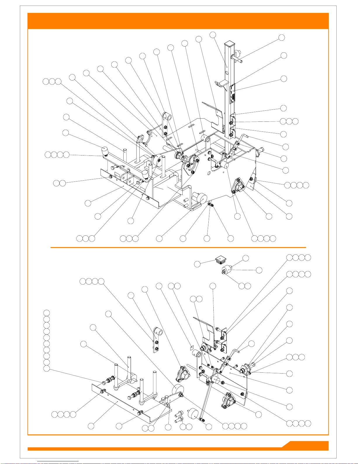
FRAME
P1.01
SP20015_REV3
OCTOBER 2017

FRAME
ITEM NO.
PART NUMBER
DESCRIPTION
CHASSIS/QTY.
1
401646_REV0
GUARD BRACKET
3
2
401820_REV0
HANDLE SPACER
1
3
402054_REV0
COLLAR
2
4
402077_REV0
TENSIONER ARM
1
5
402081_REV0
BLOCK CLAMP
2
6
402102_REV2
MAIN FRAME (DART)
1
7
402119_REV0
SPACER
1
8
402120_REV0
TENSIONER BLOCK
2
9
402125_REV0
AXLE SPACER
2
10
D1871_REV1
RIVET 3.2 X 6
2
11
D1947_REV1
GREASE NIPPLE M6
1
12
D8068_REV0
GRUB SCREW M6 X 6
4
13
D8522_REV0
CAP HEAD M10 X 35
2
14
D8955_REV1
INSERT 40MM SQUARED
1
15
E1-1061_REV0
WASHER M6 SPRING
4
16
F20080_REV0
RUBBER STOP
2
17
F21711_REV0
BUSH NYLON 008 0600 000 02
3
18
F21739_REV1
RUBBER BUFFER
3
19
F21872_REV1
BEARING BPFT5-16
2
20
F21885_REV1
BUSH AL2026 - 15
2
21
F21922_REV1
VIBRATION MOUNT (METALASTIK NO 17/1386/01 )
2
22
F22321_REV0
CLIP
2
23
F36000_REV2
SERIAL NO PLATE (SISIS)
1
24
F36369_REV4
REAR GUARD
1
25
F36474_REV2
BARREL NUT
2
26
F36502_REV1
BOTTOM BRUSH
1
27
F36669_REV1
REAR GUARD STRIP
1
28
F36670_REV1
RUBBER STRIP
1
29
F37184_REV3
TOP MOUNT
2
30
F37274_REV3
CONNECTING ROD
1
31
F37275_REV3
POINTER
1
32
F37276_REV2
LINK
1
33
F37279_REV3
GUARD STRIP
1
34
F37286_REV1
BELT FINGER
1
35
HUEO-004-81_REV1
STICKY CABLECLIP SMALL
2
36
SP01009_REV0
HEX SET SCREW M8 X 20
14
37
SP01015_REV0
HEX SET SCREW M6 X 25
2
38
SP01023_REV0
HEX SET SCREW M8 X 60
2
39
SP01028_REV0
HEX SET SCREW M6 X 20
4
40
SP01032_REV0
HEX SET SCREW M10 X 80
2
41
SP01045_REV0
HEX SET SCREW M8 X 25
10
42
SP01105_REV0
HEX SET SCREW M10 X 30
2
43
SP01120_REV0
CAP HEAD M12 X 35
8
44
SP01130_REV0
CAP HEAD M12 X 45
1
45
SP02004_REV0
NUT M6 NYLOC
5
46
SP02006_REV0
NUT M8 NYLOC (T)
28
47
SP02008_REV0
NUT M10 NYLOC (T)
4
48
SP02010_REV0
NUT M12 NYLOC (T)
2
49
SP02012_REV0
NUT M8 LOCK (THIN)
3
50
SP02013_REV0
NUT M10 LOCK (THIN)
6
51
SP03008_REV0
WASHER M8 FORM A
52
52
SP03010_REV0
WASHER M6 FORM A
15
53
SP03011_REV0
WASHER M10 FORM A
10
54
SP03012_REV0
WASHER M12 FORM A
12
55
SP03029_REV0
WASHER M8 SPRING LOCK
3
56
SP03034_REV0
WASHER M10 SPRING LOCK
6
P1.02
SP20015_REV3
OCTOBER 2017

183315
9
7
32
13
14
4
3411
20303026
1
1
6
19 31 31 24 29
8
11
20303026
2531312429
2
25
5
21
12
1217272723
35
16 28
3
3
10
34
28 22
CHASSIS
P2.01
SP20015_REV3
OCTOBER 2017

CHASSIS
ITEM NO.
PART NUMBER
DESCRIPTION
CHASSIS 2/QTY.
1
402086_REV0
UPPER LINK ARM
1
2
402089_REV0
LINK ARM
1
3
402096_REV1
LOWER FRAME
1
4
402098_REV0
FRONT WHEEL SHAFT ASSY
1
5
402101_REV0
BUSH
2
6
402126_REV0
PLUNGER
1
7
D1947_REV1
GREASE NIPPLE M6
1
8
D5622_REV0
SPLIT PIN DIA5 x 50
1
9
D8733_REV0
WHEEL
2
10
F21338_REV0
SPRING
1
11
F21466_REV0
BUSH NYLON 008 1207 000 02
4
12
F21872_REV1
BEARING BPFT5-16
2
13
F21885_REV1
BUSH AL2026 - 15
2
14
F21928_REV0
THRUST BEARING
1
15
F36351_REV1
WASHER
2
16
SP01004_REV0
HEX SET SCREW M5 X 20
1
17
SP01009_REV0
HEX SET SCREW M8 X 20
6
18
SP01045_REV0
HEX SET SCREW M8 X 25
2
19
SP01047_REV0
HEX SET SCREW M10 X 60
1
20
SP01102_REV0
HEX SET SCREW M12 X 70
2
21
SP01141_REV0
SHOULDER BOLT 12 X 20 M10
1
22
SP02002_REV0
NUT M5 NYLOC (T)
1
23
SP02006_REV0
NUT M8 NYLOC (T)
6
24
SP02007_REV0
NUT M10 STD
2
25
SP02008_REV0
NUT M10 NYLOC (T)
2
26
SP02010_REV0
NUT M12 NYLOC (T)
2
27
SP03008_REV0
WASHER M8 FORM A
12
28
SP03009_REV0
WASHER M5 FORM A
1
29
SP03011_REV0
WASHER M10 FORM A
2
30
SP03012_REV0
WASHER M12 FORM A
4
31
SP03016_REV0
WASHER M10 FORM C
4
32
SP03022_REV0
WASHER M20 FORM A
1
33
SP03029_REV0
WASHER M8 SPRING LOCK
2
34
SP13006_REV0
SPRING EXTENSION
2
35
SP14019_REV0
P CLIP 10MM NYLON
1
P2.02
SP20015_REV3
OCTOBER 2017

38
34
35
36
9
27
27
27
33
18
24
66
65
63
25
57 57
58
34
34
53535339
20 29 20
48
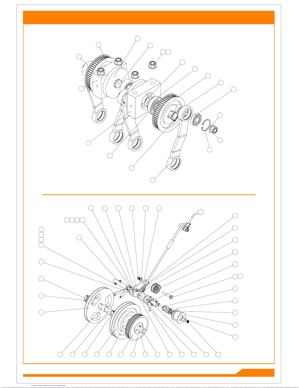
DRIVE SYSTEM
ITEM NO.
PART NUMBER
DESCRIPTION
DRIVE/QTY.
1
062276_REV0
BEARING 6207-2RS 3
4
2
229636_REV0
BUSH AM2530 - 25
2
3
401870_REV0
PULLEY BODY 38MM
1
4
402022_REV0
TIMING CRANK
2
5
402023_REV1
DRIVE CRANK
2
6
402031_REV1
CRANK
4
7
402051_REV1
SPACER
1
8
402052_REV0
SPACER
1
9
402069_REV1
PULLEY
1
10
402075_REV0
WASHER
4
P3.01
SP20015_REV3
OCTOBER 2017

DRIVE SYSTEM
ITEM NO.
PART NUMBER
DESCRIPTION
DRIVE/QTY.
11
402076_REV0
SPACER
2
12
402080_REV0
BEARING BLOCK
2
13
402118_REV0
TOP SHAFT
1
14
402121_REV0
TENSION PIVOT
1
15
402122_REV0
TENSION PIVOT
1
16
402123_REV1
SPRING RETAINER
1
17
403080_REV0
LAYSHAFT
1
18
D1558_REV1
CHAIN
1
19
D1792_REV1
EXTENSION SPRING
2
20
D1873_REV1
CHAIN
1
21
D1947_REV1
GREASE NIPPLE M6
3
22
D1986_REV0
HEX SET SCREW M5 X 20
1
23
F20184_REV1
TAPERLOCK 2517 25
1
24
F21150_REV1
BEARING BPFT5-25
2
25
F21862_REV1
HTD TOOTHED BELT
2
26
F21885_REV1
BUSH AL2026 - 15
2
27
F21890_REV1
V BELT
3
28
F21923_REV0
BUSH AM2026 - 25
2
29
F36340_REV2
SPROCKET 08B SPECIAL 13T 55T
1
30
F36344_REV1
PULLEY SPA-2 TYPE 8
1
31
F36345_REV1
SPROCKET & PULLEY SPECIAL 08B 15T
1
32
F36346_REV6
SPACER
2
33
F36375_REV1
SPROCKET 08B1 50T
1
34
F36510_REV1
DRIVE LEVER
1
35
F37284_REV1
OVER CENTRE ROD
1
36
F37285_REV3
ROD
1
37
HUGT108_REV0
CLEVIS ASSY M8 SHORT
1
38
J20017_REV1
KNOB - RED
1
39
J20406_REV0
SPLIT PIN 3/32" X 1"
2
40
J20467_REV0
GRUB SCREW M8 X 8
4
41
J209006_REV1
CIRCLIP 47 M1308-0470
4
42
J209012_REV0
WASHER M16 FORM B
4
43
J209040_REV1
BEARING 6005-2RS
4
44
J209047_REV0
TENSIONER PULLEY
1
45
SP01013_REV0
HEX SET SCREW 3/8" UNF X 2"
1
46
SP01054_REV0
HEX SET SCREW M6 X 35
2
47
SP01068_REV0
HEX SET SCREW 3/8" UNF X 2 1/2"
1
48
SP01114_REV0
GRUB SCREW M6 X 20
2
49
SP02002_REV0
NUT M5 NYLOC (T)
1
50
SP02004_REV0
NUT M6 NYLOC
2
51
SP02018_REV0
NUT 3/8" UNF NYLOC (T)
2
52
SP02028_REV0
NUT M16 NYLOC (T)
8
53
SP03008_REV0
WASHER M8 FORM A
2
54
SP03009_REV0
WASHER M5 FORM A
2
55
SP03010_REV0
WASHER M6 FORM A
4
56
SP03011_REV0
WASHER M10 FORM A
2
57
SP03012_REV0
WASHER M12 FORM A
2
58
SP05010_REV0
SPLIT PIN 1/8" X 1"
1
59
SP06012_REV0
BEARING 6200-2RS
3
60
SP07009_REV0
CIRCLIP D1400 - 035
2
61
SP07010_REV0
CIRCLIP D1400 - 032
2
62
SP07012_REV0
CIRCLIP D1300 - 030
2
63
SP10002_REV0
KEY 8 X 7 X 40 RD END
3
64
SP10006_REV0
KEY 8 X 7 X 30
4
65
SP11025_REV0
PULLEY 56-8M-20 HTD (TAPERED)
2
66
SP11026_REV0
TAPERED BUSH 2012 - 25MM
2
P3.02
SP20015_REV3
OCTOBER 2017
6
43
41
10
52
64
61
4
1
11
12
6
4
12
5
5
52 42
60
65 66 63 51
3
62
59
45
44
47 56
51 56
31
30
22
32
40
32
46
55
55
50
19
21 15
37
37
16
15 15
14 14
13
1723
22545449
26
26
7
8
DRIVE SYSTEM
P3.03
SP20015_REV3
OCTOBER 2017

25
10
5
9
23
12
18
7
243432
16
1
11
1115
16
10
7
21 4
19
9
29 26
18
7
7
23
23
21
2
2533
2533
9
5
10
26
29
9
12
301720
21
19
16
6
7
1 152016 11
243432
21
3
13 8
13 8
27 1428
32
3 2
TINE DRIVE
P4.01
SP20015_REV3
OCTOBER 2017

TINE DRIVE
ITEM NO.
PART NUMBER
DESCRIPTION
TINE DRIVE/QTY.
1
400496_REV0
PLATE
8
2
402034_REV0
SPACER
8
3
402035_REV0
SPACER
16
4
402036_REV0
SPACER
8
5
402037_REV0
LINK ARM PLATE
4
6
402038_REV0
LINK ARM PLATE
4
7
402039_REV0
PIVOT PIN
12
8
402040_REV0
WASHER
12
9
402111_REV1
TINE HOLDER
4
10
402112_REV0
BEARING HOUSING
4
11
402113_REV1
SPRING FORK
4
12
D1947_REV1
GREASE NIPPLE M6
4
13
E1-1066_REV0
WASHER SPRING M16
12
14
F21739_REV1
RUBBER BUFFER
4
15
F21987_REV1
COMPRESSION SPRING
4
16
F35946_REV7
SHAFT SWIVEL
4
17
F36407_REV3
SPACER
4
18
J20430_REV0
CAP HEAD M6 X 30
8
19
J209006_REV1
CIRCLIP 47 M1308-0470
4
20
J209012_REV0
WASHER M16 FORM B
12
21
J209040_REV1
BEARING 6005-2RS
20
22
J209085_REV1
BUSH AM1216 - 20
8
23
SP01037_REV0
HEX SET SCREW M16 X 30
12
24
SP01045_REV0
HEX SET SCREW M8 X 25
16
25
SP01120_REV0
CAP HEAD M12 X 35
8
26
SP01139_REV0
SHOULDER BOLT 12 X 55 M10
4
27
SP02004_REV0
NUT M6 NYLOC
8
28
SP02006_REV0
NUT M8 NYLOC (T)
4
29
SP02008_REV0
NUT M10 NYLOC (T)
4
30
SP02028_REV0
NUT M16 NYLOC (T)
4
31
SP02029_REV0
NUT M16 LOCK (THIN)
4
32
SP03008_REV0
WASHER M8 FORM A
20
33
SP03012_REV0
WASHER M12 FORM A
8
34
SP03029_REV0
WASHER M8 SPRING LOCK
16
P4.02
SP20015_REV3
OCTOBER 2017

5
8
1
6
7
4
1
5
3
2
9
10
ITEM NO.
PART NUMBER
DESCRIPTION
Handle Bars/QTY.
1
229754_REV0
CLUTCH LEVER
2
2
E1-1728_REV0
HEX BOLT M10 X 110
1
3
F21063_REV1
LOCK KNOB
1
4
F21905_REV0
DEADMAN LEVER
1
5
F22019_REV1
HANDLE GRIP
2
6
F36320_REV5
BACK FRAME
1
7
F36405_REV1
LABEL FORWARD DRIVE
1
8
F37288_REV1
HANDLE BARS
1
9
SP03011_REV0
WASHER M10 FORM A
1
10
SP03034_REV0
WASHER M10 SPRING LOCK
1
HANDLE BARS
P5.01
SP20015_REV3
OCTOBER 2017

5
3
71110
6
2
1
4 9 9 8
ITEM NO.
PART NUMBER
DESCRIPTION
WHEELS/QTY.
1
401650_REV0
AXLE DIFF M/C
1
2
402055_REV0
AXLE SPACER
2
3
D8733_REV0
WHEEL
2
4
E1-1116_REV0
HEX BOLT M8 X 70
2
5
F21061_REV0
WHEEL
2
6
F33607_REV1
WHEEL HUB
2
7
SP01034_REV0
HEX SET SCREW M10 X 20
8
8
SP02006_REV0
NUT M8 NYLOC (T)
2
9
SP03008_REV0
WASHER M8 FORM A
4
10
SP03011_REV0
WASHER M10 FORM A
8
11
SP03034_REV0
WASHER M10 SPRING LOCK
8
WHEELS
P6.01
SP20015_REV3
OCTOBER 2017
Table of contents
Other Sisis Lawn And Garden Equipment manuals


Popular Lawn And Garden Equipment manuals by other brands

Jonsered
Jonsered J208F24 Operator's manual

Jata hogar
Jata hogar mosquitoTRAP MELI0620 Instructions of use

ILESTO
ILESTO GUARDI GARTENBOX L BENJAMIN Construction manual

VegeBox
VegeBox Growlight HGLITE instruction manual

Toro
Toro 41339 installation instructions

Gardena
Gardena EVC 1000 operating instructions


AquaScape
AquaScape 78241 Instructions & maintenance

Superior
Superior Country Accents Arch Top Assembly instructions

SNOWJOE
SNOWJOE AJHN102-RM manual

Grouw!
Grouw! 98046 instruction manual

aidapt
aidapt VL125 Usage and maintenance instructions

New England Arbors
New England Arbors Urbanscape Raised Planter Box Assembly instructions