3Wolly2 12/12-V01
English
1.5 Safety and security precautions
Read carefully any information written in this user guide regarding installation, use and maintenance of the
central vacuum unit.
Never use inappropriately the central vacuum unit.
Never let the children get near the central vacuum unit when it is working and never let the children play with
the suction inlets or with the vacuum unit.
This tool should not be used by persons (children included) with reduced psychical, sensorial or mental
skills, or by persons without experience or knowledge, unless they are controlled or trained for the use of
the tool by people responsible of their safety.
Children have to be supervised in order to assure they don't play with the tool.
Unplug the central vacuum unit when:
The central vacuum unit has been exposed to the inclemency of the weather or to excessive moisture.
The central vacuum unit has been damaged by an impact or the external container has been damaged
The central vacuum unit requires any repairing or overhauling.
Always wear protection gloves and mask when carrying out any maintenance operation and when unloading
the dust container or replacing/cleaning the filter.
Use only original spare parts.
Never use the vacuum unit to remove textile stuff, big-size bits and pieces of any material, burning coals or
ashes.
Never vacuum liquids.
Dont use the unit without the dust collection bag and the safety filtering cartridge.
Never block the air exhaust pipes and the cooling inlets of the motor.
Never touch the suction accessories with any part of the body.
Use only one inlet at a time.
Do not let the central vacuum unit running if you are not utilising it and put the switch on the "OFF" position if
you are not going to use it for a long period.
DONT use never the unit if MOTOR COVER and BAG COVER are not assembled.
DONT unhook the unit, only qualified operators can make it for repair intervention
DONT NEVER obstruct the unit upper board when the unit is prearranged for the frontal direct air discharge,
not carried in pipe.
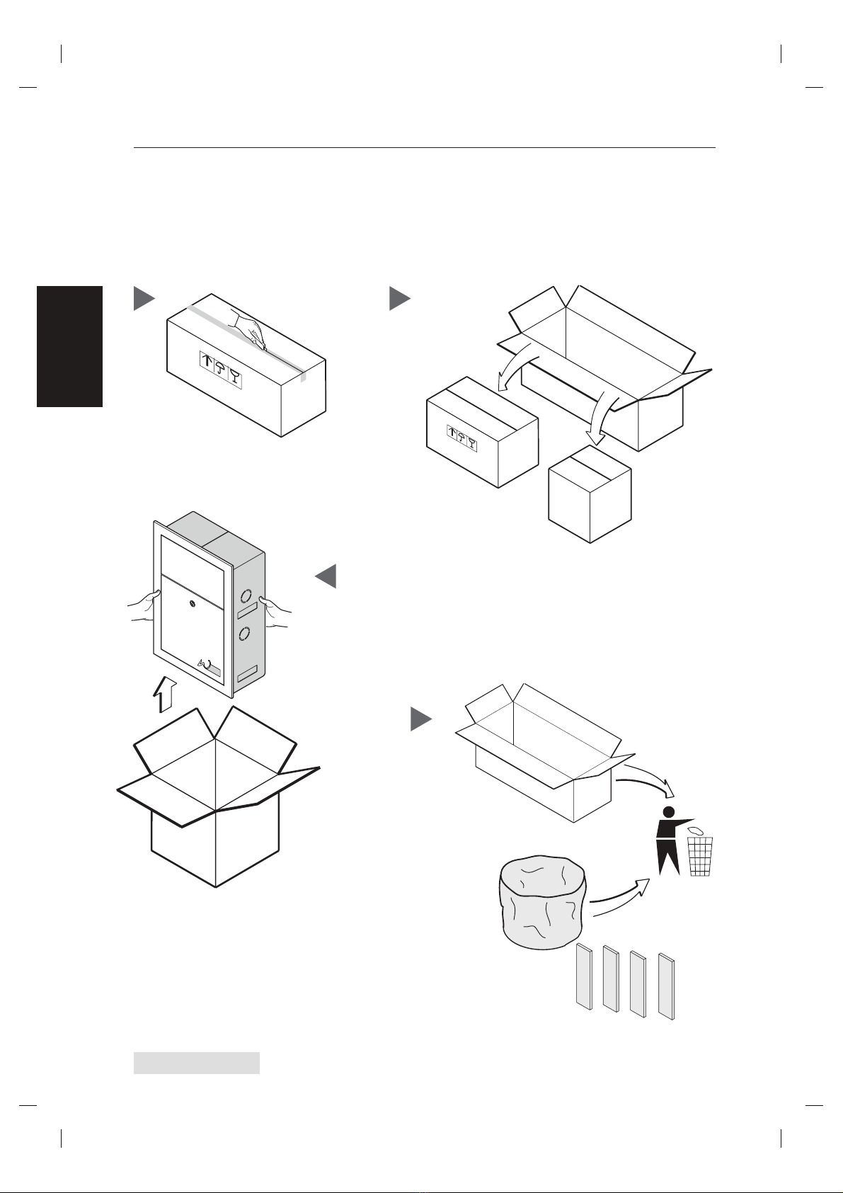
2 - HANDLING AND UNPACKING
- ATTENTION -
THE FOLLOWING OPERATIONS MUST BE CARRIED OUT
BY QUALIFIED STAFF
ALWAYS WEAR PROTECTIVE SHOES
AND GLOVESI
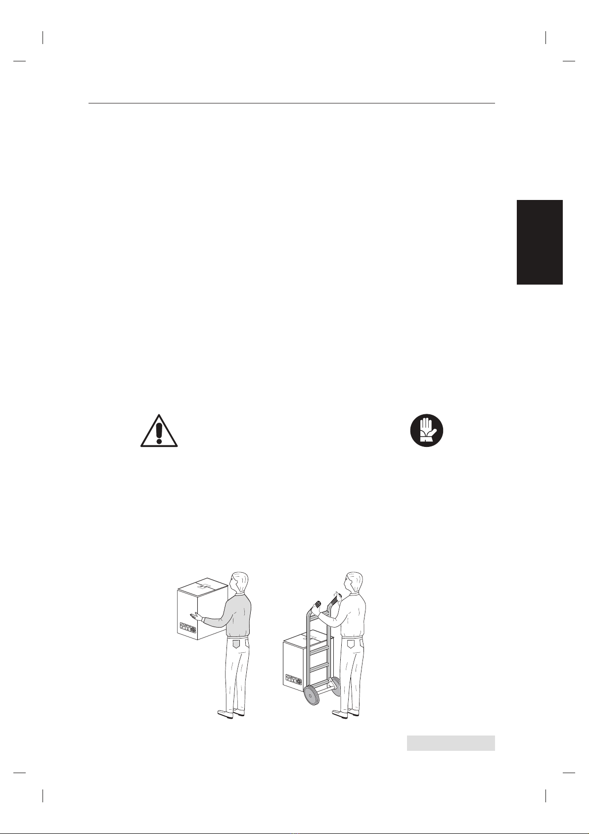
2.1 Handling and transport
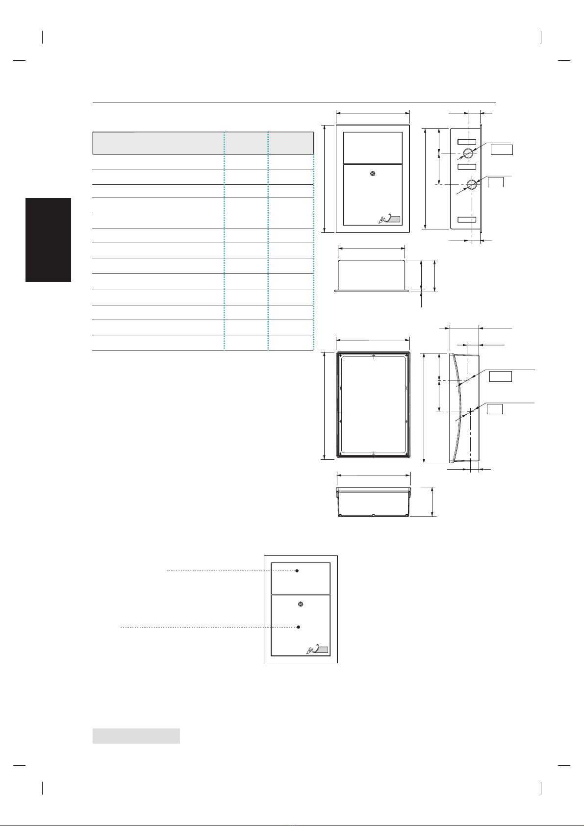
GROSS WEIGHT: kg XX
PACKING DIMENSION: cm XX x XX x H XX
CENTRAL UNIT WEIGHT: kg XX.X
Place the central unit still packed near the location of installation.
The small dimensions and the light weight do not require any special handling system. If necessary, use a trolley
or ask for somebody's help.