Sit 849 Sigma MOD-S Technical manual

9.957.113 C00
ONLY FOR VERSIONS WITH VENT DIAMETER LARGHER THAN 0.56 mm
SIT code: 0.xxx.xxx
849 Sigma MOD-S
USE AND INSTALLATION INSTRUCTIONS
Read the instructions before use. This control must be installed in accordance with the rules in force.

2
849 Sigma mOD-S USE aND iNSTaLLaTiON iNSTRUCTiONS
1
3
7
7
Fig. 1
4
6
2
5

3
849 Sigma mOD-S USE aND iNSTaLLaTiON iNSTRUCTiONS
MAIN FEATURES
•
Inlet filter (FL)
•
Inlet and outlet pressure test points with “captured” screws (Pin, Pout)
•
Servo pressure regulator (PR)
•
Current controlled modulating device (MD)
•
Gas flow sensor (SENS)
DESCRIPTION
See Fig. 1:
1. Inlet pressure test point (Pin)
2. Outlet pressure test point (Pout)
3. Modulating device terminals
4. Gas flow sensor terminals
5. Gas inlet with protective dust cover
6. Gas outlet with protective dust cover
7. Valve mounting holes
GAS
INLET
FLI
EV1
RP
EV2
MAIN
BURNER
PILOT
BURNER
FLP
FLO
PA
GAS
INLET
FL PR
PILO
T
BURNER
FLP
PA
MD
Pin
RESTRICTOR
GAS
OUTLET
SENS
Pout
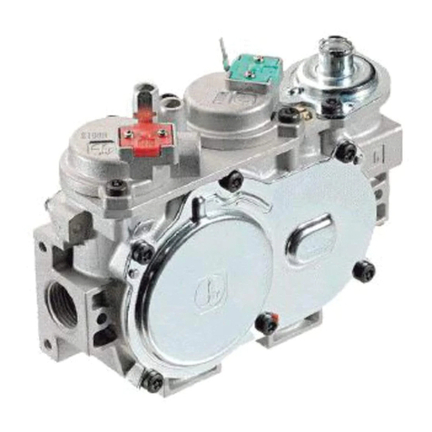
Multifunctional gas control with a pressure regulator, a current controlled modulating device and a
gas flow sensor. The location for gas orifice (restrictor) is on the outlet of the multifunctional control.
The control is designed for use in domestic gas appliances using 2nd and 3rd gas families.
The designed lifetime* of this product is 500 000 cycles or 10 years (based on date code)
according to the standard EN 126 and the table on designed lifetime as stated in the Afecor
document, see http://www.afecor.org/news.html.
This lifetime is based on the use of the control in accordance with the appliance manufacturer’s
instructions.
Regular inspection of the control by authorized personnel in accordance with guidelines of the
appliance manufacturer is required.
After reaching the designed lifetime the product has to be replaced by authorized personnel.
*The warranty as opposed to the designed lifetime is described in the delivery terms.

4
849 Sigma mOD-S USE aND iNSTaLLaTiON iNSTRUCTiONS
TECHNICAL DATA
The technical data specified below refers to the European standards EN 126 “Multifunctional
controls for gas-burning appliances”.
Gas families 2nd, 3rd
Maximum inlet pressure 60 mbar
Ambient temperature range 0 to 60 °C
Storage temperature range -30 to 70 °C
Torsion and bending resistance Group 2
Maximum Humidity 95% RH at 40 °C
Assembly position All positions except upside down
Inlet gas connection Suitable for nut compliant with male G3/4 B ISO 228
Outlet gas connection Suitable for nut compliant with male G3/4 B ISO 228
Pressure test point ∅9 mm
Pressure regulating function
This is obtained by means of the servo regulator type with pressure compensation connection.
Pressure regulator Class B
Minimum gas flow 0.03 m3/h for 2nd family gas (G20)
Capacity @ 5 mbar pressure drop More than 1.6 m3/h (G20)
Modulating function
The pressure Pint is function of the modulator dc current. The reference of the pressure regulator is
the pressure at GAS OUTLET, internally connected.
Therefore the differential pressure across the gas orifice DP (= Pint – GAS OUTLET) is function of
the modulator current, see graph below.
α=0
α
α=π/2
Response time Less than 2 seconds
Maximum modulator voltage @20°C [V]10
Modulator modulator current @20°C [mA]40
Modulator resistance @20°C [W] 176 ± 6%
Offset [mbar] , see Fig. below 4.35 ( cosa - 1)

5
849 Sigma mOD-S USE aND iNSTaLLaTiON iNSTRUCTiONS
0
2
4
6
8
10
12
14
16
Modulator current [mA]
∆P [mbar]
Modulating characteristic with vertical modulator axis (α=0)
a
a=0
OFFSET
Gas Flow Sensor diagram
Output sensor [reading as decimal fixed point].
0
3000
6000
9000
12000
15000
18000
0100 200 300 400 500 600
MASS FLOW [Nl/h]
OUTPUT VALUE
G31
G271
G21
G20
Gas Flow Sensor
Supply voltage 3.3 Vdc
Output I2C protocol

6
849 Sigma mOD-S USE aND iNSTaLLaTiON iNSTRUCTiONS
INSTALLATION
849 Sigma MOD-S conforms to current safety standards. Installation on appliances must
nevertheless be checked with respect to the specific installation requirements for the appliance.
All the installation and adjustment operations must be carried out exclusively by qualified
personnel and on the basis of the specific characteristics of the user appliance and following the
instructions given in this booklet. All other operations are absolutely forbidden.
The control is not suitable for outdoor operation.
WARNING
CONDENSATION, FORMATION OF ICE AND INGRESS OF WATER ON
THE GAS VALVE ARE NOT PERMITTED.
WARNING
849 SIGMA MOD-S MUST BE USED SO THAT THERE CAN BE NO
GAS DEMAND IF THERE IS NO AIR FLOW.
IMPORTANT
Do not tamper with sealed parts
Do not remove labels
Only remove dust caps when installing (dust caps do not guarantee
sealing)
Do not exceed recommended torques
Use only the specified spanner grips shows in Fig.3 when making the
connections
Turn off gas supply before starting installation
WARNING
DO NOT SLACKEN ASSEMBLY SCREWS
WARNING
AVOID BLOWS (KNOCKS, FALLS ETC.)
WARNING
ENSURE THAT THE GAS FLOWS IN THE DIRECTION SHOWN BY
THE ARROW ON THE VALVE BODY
WARNING
DO NOT IMMERSE IN WATER OR SUBJECT THE MULTIFUNCTIONAL
GAS CONTROL TO TEMPERATURES EXCEEDING 70°C
WARNING
IF A SINGLE VALVE FALLS, DO NOT USE FOR PERFORMANCE AND
SAFETY REASONS

7
849 Sigma mOD-S USE aND iNSTaLLaTiON iNSTRUCTiONS
WARNING
DO NOT SUBJECT THE VALVE TO BENDING IN EXCESS OF 35 NM
AND TORQUE IN EXCESS OF 25 NM
WARNING
IN CASE OF OVERPRESSURE OF THE INPUT GAS ON THE VALVE
GREATER THAN 1 BAR, REPLACE THE VALVE.
WARNING
DO NOT OPEN, INTERFERE WITH OR MODIFY THE VALVE.
WARNING
IN GENERAL, USE NEW GASKETS AFTER REMOVING AND PUTTING
BACK OF ANY PARTS.
Gas restrictor fitting
See the figures below and follow the sequence (a) - (b). Insert completely the restrictor into the
outlet gas connection. Make sure that the restrictor does not interfere with the reference pressure
opening located inside the gas outlet, see the detail in the enlarged picture below.
(a)
(b)
Restrictor
Reference pressure opening
Restrictor

8
849 Sigma mOD-S USE aND iNSTaLLaTiON iNSTRUCTiONS
Gas inlet Gas outlet
Pipe
Connection with gasket
Locking ring
Gasket
Pipe
Connection with gasket
Locking ring
Gasket
Inlet and outlet gas connections with gasket
Use gas pipes with a suitable flat annular surface to allow the use of a sealing gasket, see Fig 2.
In particular for outlet connection, make sure that the gasket does not interfere with
the fitted restrictor and make sure that the surface of the gasket does not obstruct the
space beetwen the restrictor and the outlet pipe, see enlarged view in Fig.2.
The locking ring thread shall comply with ISO 228.
Ensure the gasket is suitable for the application.
Apply the proper torque to the locking ring, according to the washer characteristics, in order to
ensure the seal.
Fastening torque: maximum 50 Nm
minimum 30 Nm
WARNING
DO NOT OVER-TIGHTEN THE LOCKING RING. COUNTERBALANCE
THE TORQUE (SEE EXAMPLE IN FIG. 3).
Fig. 3
Fig. 2
Restrictor Gasket
41 mm

9
849 Sigma mOD-S USE aND iNSTaLLaTiON iNSTRUCTiONS
Electrical connections
All electrical connections must be made in accordance with current electrical standards. Check
that the voltages given to the modulator and to the sensor are correct. Disconnect the power
supply before starting installation. Check that all connections are made properly
The modulator is supplied with a male contact Molex compatible, suitable for female Molex series
70066 connector.
The gas flow sensor is supplied with a male contact Molex compatible, suitable for female Molex
series 87369 connector.
Check that the polarity of the connections are made properly as shown in Fig. 4.
Make the connections as specified in the technical instructions for the automatic burner control
used and/or in the specific standards for the appliance.
Wiring diagram
The connection diagram is given in Fig. 4.
1
2
3
4
EV1
EV2
MD
Fig.4
WARNING
CONDENSATION, FORMATION OF ICE AND INGRESS OF WATER ON
THE COIL TERMINALS ARE NOT PERMITTED.
CLK
V+
GND
DATA

10
849 Sigma mOD-S USE aND iNSTaLLaTiON iNSTRUCTiONS
SETTINGS AND ADJUSTMENTS
There are not any adjustments in this multifunctional control. Check inlet and intermediate
pressure using the pressure test points provided. To open the pressure test points use a 4.9 mm
screwdriver for slot-head screws. After setting, carefully seal test points ensuring gas soundness.
Recommended torque: 1.0 Nm.
At the end of all checking operations, check electrical insulation, gas seals and
the safety of the appliance. Finally ensure that the burner operates properly at
the minimum and maximum power of the appliance.
IMPORTANT

11
849 Sigma mOD-S USE aND iNSTaLLaTiON iNSTRUCTiONS
DIMENSIONAL DRAWING OF THE MULTIFUNCTIONAL GAS CONTROL

Table of contents
Other Sit Control Unit manuals
