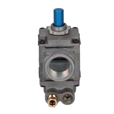
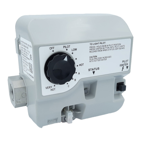
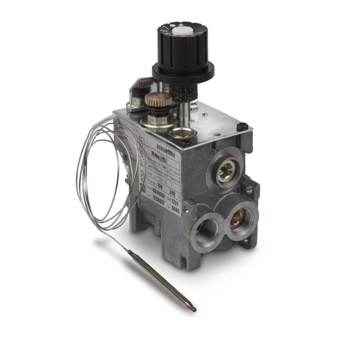
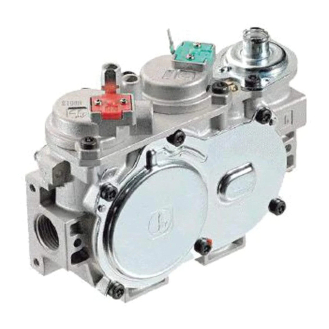
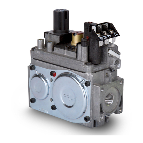
Sit 650 DELTA Technical manual

9.957.059 04
650 DELTA
USE AND INSTALLATION INSTRUCTIONS
Read the instructions before use. This control must be installed in accordance with the rules in force.

650 DELTA USE AND INSTALLATION INSTRUCTIONS
MAIN FEATURES
•
Inlet filter (FL)
•
Control knob for off, pilot and temperature selection (MS)
•
Thermoelectric flame supervision device (GM)
•
Non-resettable safety thermostat (TL)
•
ON/OFF adjustable thermostat (TH)
•
Pressure regulator on main burner (PR)
•
Pilot filter (PFL)
•
Pressure regulator on pilot burner (PPR)
•
Outlet pressure test point
650 DELTA is a combination gas control with thermoelectric flame supervision device and ON/OFF
thermostatic control.
650 DELTA is designed and intended for gas fired storage water heaters.
2
TECHNICAL DATA
Inlet gas connection 1/2” NPT
Main burner outlet 0.7500 - 18 - UNS 2B inverted flare
Pilot outlet 7/16”- 24 - UNS 2B
Mounting shank 3/4” NPT
Thermocouple connection 11/32” ASA
Outlet pressure test point 1/8” NPT
Installation position any position with shank in horizontal position
Gas families Natural Gas or Liquefied Petroleum Gas
Maximum inlet pressure 1/2 PSI
Main outlet pressure setting range 3"... 5" w.c. for NG and 8"...12" w.c. for LPG
Pilot outlet pressure setting range 3"... 6" w.c. for NG and 8"...12" w.c. for LPG
Ambient temperature range 32...175 °F
GM
INLET
MAIN
PILOT
BURNER
BURNER
TH
PR
PPR
PFL
TL
MS
FL
GAS

650 DELTA USE AND INSTALLATION INSTRUCTIONS
3
VALVE DESCRIPTION
1 Ignition button for thermoelectric flame
supervision device
2 Control knob
3 Reference arrow mark
4 Gas inlet with protective dust cap
5 Main gas outlet with protective dust
cap
6 Pilot outlet
8 Outlet pressure test point
9 Thermocouple connection
10 Mounting flange
11 Thermostat Rod
12 ECO Well
13 Piezoelectric igniter (Optional)
14 Plastic cover (Optional)
10
2
11
8
5
9
THERMOSTAT REGULATION SPECIFICATIONS
Thermostat Features
•
Regulating thermostat
Differential (a) 16 +/-5.5 °F
•
ECO
Type one-shot
Calibration 196 +0/-9 °F
TEMPERATURE
a
GAS FLOW
a
A B
MIN position MAX position
control knob at control knob at
STOP
Do not install, replace, or in any way modify the gas valve or the appliance. Always
use a QUALIFIED Gas Appliance Service Technician to service appliances this valve is
installed on. ALWAYS READ AND FOLLOW ALL THE ENCLOSED INTRUCTIONS.
12
4
14
2
4
13
96
13
3
1
4
11
12

650 DELTA USE AND INSTALLATION INSTRUCTIONS
4
INSTALLATION
When installation of this product begins…
1. Read all of these instructions carefully. Failure to follow these instructions could damage the
product or cause dangerous conditions.
2. Check the ratings given in the instructions and on the appliance to make certain that the control
is suitable for your application.
3. All operations of installation, setting and adjustments must be undertaken exclusively
by a qualified Gas Appliance Service Technician following the instruction specified in this
catalog and those in the instruction manual of the appliance in which the valve is installed.
4. After installation is complete, verify that the appliance is operating as indicated in these
instructions.
WARNING!
Oxygen Depletion Hazard.
Can cause injury or death by asphyxiation.
Do not use valves for vented appliances on unvented or vent free appliances. Do not use
valves for unvented or vent free appliances on vented appliances.
WARNING!
Fire or Explosion Hazard.
Can cause property damage, severe injury or death.
Follow these instructions completely.
1. Turn off gas supply to the appliance before installation, and perform Gas
Leak Test after the installation is completed.
2. Always install the sediment trap in the gas supply line to prevent contamination of the
gas control.
3. Do not force the control knob. Use only your hand to turn the knob. If the knob does
not move by hand, the valve should be replaced by a qualified service technician.
CAUTION!
Electrical shock or equipment damage hazard.
Can shock individuals or short equipment circuitry.
Make sure to disconnect all electrical supplies before beginning the installation process.
IMPORTANT
•
These gas controls are shipped with anti-contamination seals over inlets and outlets.
•
Do not remove the seals until ready for connection to piping; remove dust caps only
when installing.
WARNING!
Avoid any foreign matter getting into the device, check inlet and outlet pipes for cleanness.
WARNING!
In case of overpressure of the input gas on the valve greater than 14.5 PSI, replace the valve.

650 DELTA USE AND INSTALLATION INSTRUCTIONS
INSTALLING THE VALVE
1. Install the valve using the provided mounting flange.
Screw using using the specific tool SIT code 0.999.996,
suitable as accessory. Tighten to 45 ÷ 60 ft·bs torque.
2. Mount the valve so the flow of gas is consistent with
the gas flow arrows on the valve.
3.Apply a moderate amount of quality
pipecompound to the pipe only, leaving two end
threads bare. On LP installations, use compound
that resists exposure to LP gas.
4. Remove seals over inlet and outlet if necessary.
5. Connect pipe to valve inlet and outlet. Place wrench on
valve in position
(see Fig. 2). Tighten inlet connection
to 30 ft
·
lbs torque, outlet connection to 20 +/-10 ft
·
lbs
torque.
6. Thread pipe into the valve until a gas tight seal is
achieved. Typically, for NPT thread, penetration is
usually no more than the diameter of the pipe or 2
and 1/4 turns thread. Valve distortion or mechanical
failure can result if the pipe is inserted too deeply.
7. Connect pilot tubing to valve with appropriately
sized fittings. Recommended torque 40 ÷ 70 lbf·in.
8. Confirm gas tight seals with gas leak test.
9. Connect thermocouple to safety magnet. Hand tighten, and then rotate 1/4 turn with wrench
appling a torque not higher than 10 ÷ 20 lbf·in.
5
INSTALL PIPING TO GAS VALVE
All piping must comply with local codes and ordinances or with the National Fuel Gas code (ANSI
Z223.1 NFPA No. 54) whichever applies. Tubing installation must comply with approved standards
and practices. Use appropriately sized fittings when
connecting aluminum tubing to the pilot outlet.
1. Use new, clean and correctly reamed pipe free from
burrs, chips, debris and any foreign matter. When
tubing is used, make sure the ends are square
and clean. All tubing bends must be smooth and
without deformation.
2. Run pipe or tubing to the valve. If tubing is used,
obtain a tube-to-pipe coupling to connect the tubing to the valve.
3. Install sediment trap (Drip Leg) in the supply line to the gas valve.
3” MIN.
GAS SUPPLY
TO CONTROL
INLET
DRIP LEG (DOWN)
WARNING!
Do not immerse in water or subject the control to temperatures exeeding 175 °F
operating ambient temperature..
28 mm
29 mm
Fig. 2
Fig. 1

650 DELTA USE AND INSTALLATION INSTRUCTIONS
6
WARNING!
DO NOT OPERATE THE DEVICE WHEN THE STORAGE WATER HEATER IS NOT FILLED WITH WATER.
WARNING!
•
Do not tamper with sealed parts.
•
Do not loosen assembly screws.
•
Do not remove labels and marking.
WARNING!
Observe recomended torques.
Use only specified spanner grips when making the connections (see Fig. 1 and Fig. 2).
WARNING!
AVOID ANY DAMAGE TO THE DEVICE (KNOCKS,FALLS,ETC.). IN CASE OF FALL OF THE
VALVE, IT IS RECOMMENDED NOT TO USE IT.
OPERATION
STOP!
It is imperative that you read and follow all safety warnings before lighting the pilot burner.
Refer to ANSI Z21.10 and ANSI Z21.78.
WARNING!
If you do not follow these instructions exactly, a fire or explosion may result causing property
damage, personal injury, or loss of life.
WARNING!
Make certain that the water heater is completely filled with water before attempting to ignite the
pilot burner or otherwise operate the gas control.
Note:
All knob settings referenced to the reference arrow marks (a) in
Fig. 3.
IMPORTANT:
Always start operation from the OFF position of the control knob.
Pilot flame ignition
Start from the OFF position (Fig.3). Rotate the control
knob
counter-clockwise
to the PILOT position (Fig.4).
Press and hold the ignition button PILOT (b) for thirty (30)
seconds or more and simultaneously press several times
the Piezo Igniter button (c) to light the pilot flame (Fig.5).
Release the ignition button PILOT and make sure that the
CAUTION!
Wait a minimum of (5) five minutes before attempting to re-light the
pilot burner after the gas control has been switched to the OFF position
and/or the pilot flame has been extinguished. Repeat the pilot ignitionRepeat the pilot ignition
sequence starting from the OFF position. (Fig. 3)
(a)
Fig. 3: OFF position
WARNING!
THE 650 DELTA VALVE IS DISPOSABLE. THE VALVE ALREADY MOUNTED ON A STORAGE WATER HEATER
MUST NOT BE REMOVED FROM THE STORAGE WATER FOR REUSE ON ANOTHER WATER HEATER.

650 DELTA USE AND INSTALLATION INSTRUCTIONS
7
Main burner ignition
Turn the control knob counter-clockwise to the ON
position (Fig.6).
Gas will flow to the main burner when the
water temperature stored within the appliance is lower than
the set-point temperature.
Temperature setting
To increase the water temperature set-point rotate the control
knob counter-clockwise to the desired temperature
setting
(Fig.7)
. The gas path to the main burner opens when
the water temperature within the appliance is lower than the
temperature set-point.
To decrease the water temperature set-point, rotate the
control knob clockwise to the desired temperature
setting
(Fig.8)
. The gas path to the main burner opens when
the water temperature within the appliance is lower than the
temperature set-point.
Stand-by position
To maintain a flame at the pilot burner with the main burner
off, turn the control knob
clockwise
to the PILOT
position (Fig.9).
Turning off
Turn the control knob
clockwise
to the OFF position
(Fig.10).
Fig. 6: ON position
Fig. 4: PILOT position
Fig. 7: LOW position
Fig. 8: VERY HOT position
Fig. 9: PILOT position
Fig. 10: OFF position
pilot flame remains lit. If it goes out, repeat the ignition process, starting from the OFF position.
Fig. 5: Ignition button PILOT
and Piezo Igniter button
(b)
(c)

650 DELTA USE AND INSTALLATION INSTRUCTIONS
PERFORM GAS LEAK TEST
GAS LEAK TEST
•
Using a solution of soapy water, paint the piping connections, which are upstream of the
control.
The presence of bubbles indicates a gas leak.
If a leak is detected, tighten the pipe connections and repeat leak test.
•
Light the main burner following the lighting instructions..
•
With the main burner in operation, paint all piping connections from the valve with a soap and
water solution.
•
If another leak is detected, tighten the connection.
•
If after tightening the connections the leak is still present, replace the leaky part or valve. Shut
off the main gas supply before attempting replacement of parts or the valve.
WARNING!
Stand away from the main burner while lighting.
Hidden gas leaks can cause flashbacks in the appliance area. Check for gas leaks with rich
soap and water solution any time work is done on a gas system.
WARNING!
Fire or Explosion hazard.
Can cause damage to property and severe injury or death.
Do not force the control knob. Use only your hand to turn the knob. If the knob does not move
by hand, the valve should be replaced by a trained service technician.
FINAL CHECKS
SETTINGS AND ADJUSTMENTS
The valve is preset at the factory, and is not field
adjustable.
Verify the outlet pressure via the 1/8”NPT outlet pressure
test plug (8 in Fig. 11). Upon completion of testing, the
sealing plug must be reinstalled using a 3/16” hex key,
with 22 lbf·in of torque and a gas leak test must be
performed.
8
8
Fig. 11

650 DELTA USE AND INSTALLATION INSTRUCTIONS
WARNING!
Fire or Explosion Hazard.
Can cause severe injury or death.
Perform the safety shutdown check any time work is done on a gas system.
1. Place the appliance in operation. The pilot and main burners should be lit.
2. Place gas control knob in PILOT position. Main burner should extinguish and pilot should
remain lit.
3. Extinguish pilot flame. Pilot gas safety shutoff proves complete shutdown due to the fact the
safety shutoff valve prohibits main burner and pilot gas flow.
4. Wait at least five minutes for the safety magnet to reset and residual gas to clear from the
combustion chamber.
5. Relight pilot burner and operate the system through one complete cycle to ensure all functions
operate correctly.
SHUTDOWN PERFORMANCE TEST
9

650 DELTA USE AND INSTALLATION INSTRUCTIONS
10
WARNING!
The piezoelectric igniter should be replaced by a qualified service technician.
The appliance and the gas valve may be hot: wait until the temperature has dropped before
touching the appliance or the gas valve.
1.Turn the control knob of the gas valve
clockwise
to the OFF position.
2. Turn off gas supply at the appliance service valve.
3. Remove the female cable connector from the male igniter connector.
4. Remove the old igniter from the gas valve making lever with a flat screwdriver of appropriate
size, as shown in Fig.12 & 13. Discard the old igniter.
5. Position the new igniter, available as spare part SIT code 0073002, into his seat of the gas
valve, as shown in Fig.14. Apply by hand a maximum force of 44 lbf (20 Kgf ) on the button of
the igniter. The applied force makes operating the igniter which will generate one click and one
spark in air. Continuing to apply the force, a second click is made. The second click confirms
full insertion and the mechanical locking of the body of the new igniter into its seat, as shown in
Fig. 15. Once inserted, do not remove the igniter.
6. Reconnect the female connector of the electric cable to the male igniter connector.
7. Relight pilot burner and operate the system through one complete cycle to ensure all functions
are correct.
PIEZOELECTRIC IGNITER REPLACEMENT
Fig. 13
Fig. 15
Fig. 12
Fig. 14

650 DELTA USE AND INSTALLATION INSTRUCTIONS
11
DIMENSIONAL DRAWING
Dimensions are in millimeters.

Other Sit Control Unit manuals
Popular Control Unit manuals by other brands

Pentair
Pentair ERICO CADWELD PLUS Operation instructions

AUZA
AUZA WAVE PACKETS quick start guide

jcm-tech
jcm-tech RB3 TGLA868 user manual
resideo
resideo Braukmann BA295D-3/4WH installation instructions

ICPDAS
ICPDAS HRT-710 user manual
Power Computing
Power Computing PowerCenter Pro Low Profile 180/210 manual

Eaton
Eaton XN300 manual
Mitsubishi Heavy Industries
Mitsubishi Heavy Industries SC-SL2N-E installation manual
Realtek
Realtek UWB BG13 HMC user guide

Johnson Controls
Johnson Controls GS-20 Series Installation Sheets Manual
Becker
Becker Centronic SunWindControl SWC445-II Assembly and operating instructions
National Instruments
National Instruments NI 9423 operating instructions
