Sititek GROM E20 User manual
SITITEK GROMЕ20 BIRD REPELLER
Manual

CONTENTS
1
Device description and operation
1.1
Device purpose
1.2
Technical specifications
1.3
Device configuration
1.4
Device operation
2
Intended use
2.1
Operating restrictions
2.2
Device usage
3
Maintenance
4
Typical problems
5
Packaging, storage and transportation
6
Manufacturer warranty

This User Manual includes key features, operating instructions (intended use, maintenance, repair,
storage and transportation) of SITITEK GROM E20 Bird repeller (hereinafter –device).
Before using the device, please, carefully read the supplied User Manual.
The device has a long service life and works efficiently if used according to the Manual’s recommenda-
tions.
1 DEVICE DESCRIPTION AND OPERATION
1.1. Device purpose
1.1.1 The device is an acoustic bird repeller designed for protection of agricultural facilities (crops,
grain fields, vineyards, gardens), air fields, fishing vessels, etc. against birds.
Most birds (sparrows, starlings, blackbirds) bring serious harm to gardeners, winegrowers and farmers
damaging the significant part of crops during the harvest season. At the same time, during the nesting
period they kill a huge number of plant pests, so the complete elimination of birds is not acceptable.
The operating principle is based on the birds’ instinctive reaction to loud sounds. The sound brings no
physical damage to birds, but it scares them away and makes them escape the area.
Propane gas is supplied from a gas tank to a combustion chamber, where the spark plug ignites it and
causes a shot. The cannon significantly enhances the sound and the sound pressure level reaches 130 dB.
1.1.2 Features:
•Large protection range (more than 215 000 ft²(20 000 m²) allows to protect large farms, agricultural
fields, production facilities territories, hangars, granaries, etc.
•Reliable protection against precipitation.
•Flexible settings of repelling modes (day, night, 24/7; single shots/series of shots; adjustable
pauses).
•External power source.
•Remote control capability.
•Battery level monitoring feature.
1.1.3 Device operating conditions:
- Surrounding air temperature, .............................................……from -4 to 104 ℉(from -20 to 40 ◦С)
- Relative air humidity at 77 ℉(25 ◦С), .......................................................………………. up to 98%
- Atmospheric pressure, ...........................… ……….from 66,6 to 106,6 kPa (from 500 to 800 mmHg)
1.2. Technical specifications
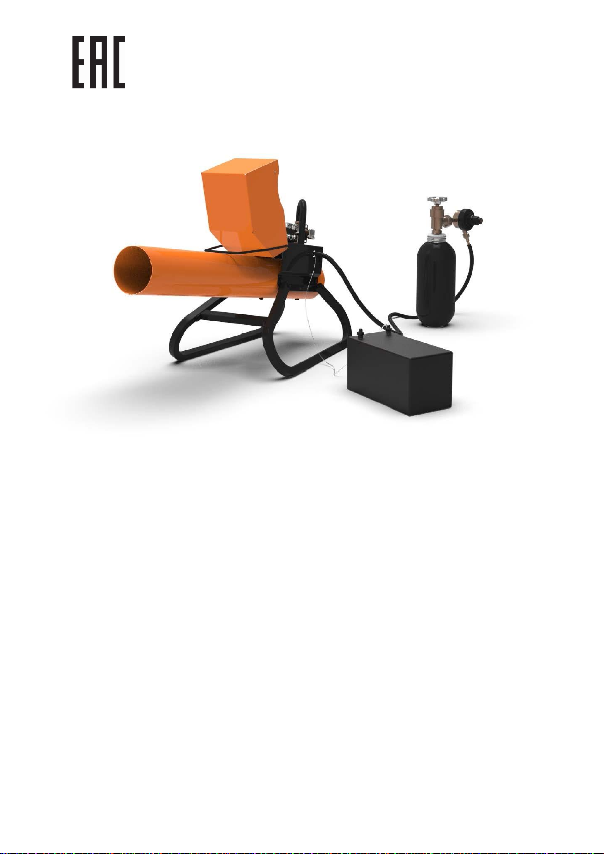
1.2.1 Visual appearance of the device is shown on Figure 1.
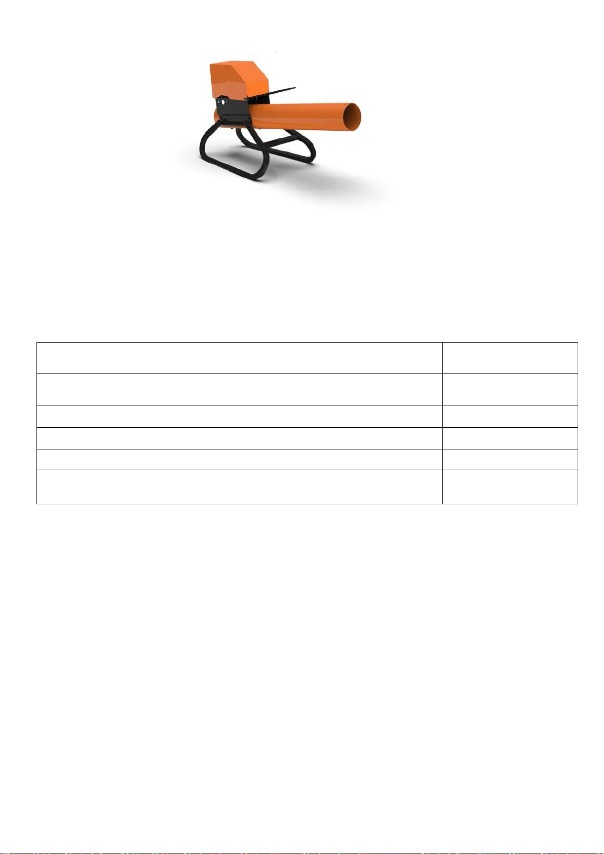
Figure 1 - Visual appearance of the device
1.2.2 Technical specifications are shown in Table 1.
Table 1
Dimensions
39 x 22 x 18 in
(990х550х450 mm)
Device weight
15,4 lb (7 kg)
Weight of packed device with gas reducer
20 lb (9 kg)
External source of power supply
12±1,5V
Gas type
Propane/butane
Gas consumption
22 lb (10 kg) of propane
for 17000 shots

Current consumption:
- in standby mode
- during shot
0,05A
1,5A
Modes
remote control, day,
night, 24/7
Random pauses between shots
Yes
Number of shots in series
1, 2, 3, 4
Length of pauses between the series of shots
From 1 to 60 min
Sound pressure level at 1 m distance (3.3 ft)
Up to 130
Maximum protection area
Up to 215 000 ft² (20000
m²)
1.2.3 IP code 54 (protection from dust and water splashes).
1.3 Package content
1.3.1 Package content is shown in Table 2.
Table 2
№
Description
Quantity
1
SITITEK GROM Е20 bird repeller
1
2
Propane gas reducer
1
3
Stands
2
4
Spacer
1
5
М6х40 screw
4
6
М6х12 screw
2
7
Individual package
1
8
Manual
1
1.3.2 The device’s configuration is shown on Figure 2.

Figure 2 –The device’s configuration
1–Cannon
2–Protective visor
3–Handle
4–Stands
5–Main body
6–Control unit
7–Control unit cover
8–Pneumatic valve
9–Light sensor
10 –М6х12 screw
11 –М6х40 screw
12 –Gas hose
13 –Gas reducer
14 –Gas tank (not included)

15 –Spacer
16 –Battery (not included)
17 –Power cable
18 –Spark plug
19 –High-voltage cable
20 –Spark plug cap
1.4. Operation
1.4.1 The gas is supplied from a gas tank to the combustion chamber, where the spark plug ignites gas
and causes a loud shot.
1.4.2 The device is managed by control unit.
1.4.3 The device is powered by 12V external power supply (e.g. car battery).
2. INTENDED USE
2.1 Operating restrictions
2.1.1 Please, carefully read the Manual and rules of operation and storage of gas tanks before using the
device.
2.1.2 Outdoor use only.
2.1.3 Use only propane or butane gas.
2.1.4 Wear protective earmuffs while the device is operating.
2.1.5 Do not look inside the cannon!
2.1.6 Do not smoke next to the cannon!
2.1.7. Do not put anything inside the cannon!
2.1.8 Use the device and gas tank far from heaters and fire.
2.1.9 The gas tank must be installed in an upright position only.
2.1.10 Do not use the device in pits and hollows. In case of a leak, the gas will accumulate in low places.
2.1.11 Install the device at a safe distance from explosive and inflammable materials to avoid fire.
2.1.12 In case of fire, close the gas tank valve and put out the fire with fire extinguisher.
2.1.13 If you smell the gas, close the gas tank valve and turn off the device, disconnect the battery. Find
out the reason of a leak.
2.1.14. Inspect the hoses and replace them in case of cracks and damages.
2.1.15 Keep the device out of children.
2.1.16 Do not open, repair and adjust gas reducer on your own.
2.1.17 Use the device with closed protective visor as water can damage the device.
2.2 Device usage
2.2.1 Assembling.
Open the box. Install the stands (4, Figure 2) to th e ma in b od y ( 5 , F ig ur e 2) us in g 4 М 6х 40

screws. Connect the spacer (15, Figure 2) between the stands (4, Figure 2) using
2 М6 х1 2 sc re ws .
Make sure O-ring is on the connecting parts of the gas reducer. Connect the reducer (13, Figure 2) to a
gas tank (14, Figure 2) (not included). Turn the connecting (cap) nut of the reducer with a wrench
counter-clockwise.
The device is ready to use.
2.2.2 Assembling the device and preparing for operation.
ATTENTION! Do not open the gas supply and do not connect the device with battery until assembling is
finished.
2.2.2.1 Use the switch panel to adjust the device (Figures 3, 4).
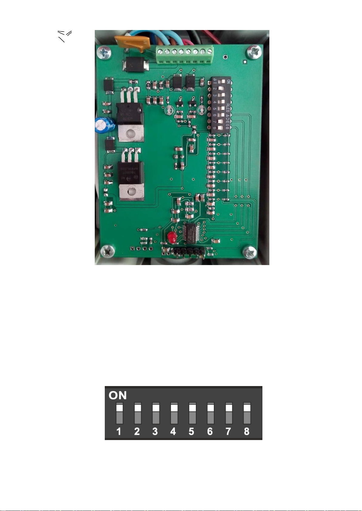
Figure 3 –Control unit
1–Power and battery charge LED indicator
2–Gas supply LED indicator (opening of pneumatic valve)
3–Spark plug operation LED indicator
4–Switch panel
5–Screw terminal
Figure 4 –Switch panel
5
2
3
4
1
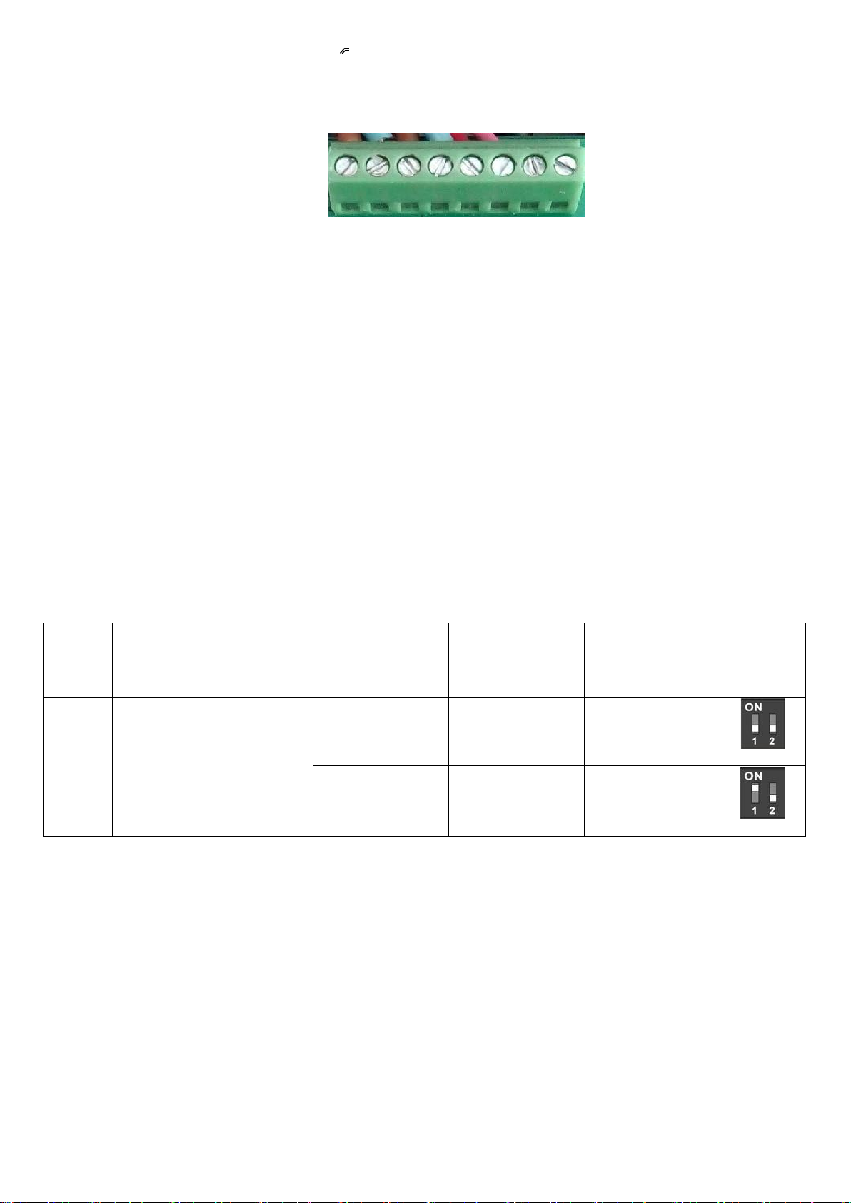
Figure 5 –Screw terminal (for remote control connection)
2.2.2.2 External control device (e.g. wired remote control) connects with a use of screw terminal. Control
device connects to the retention screws according to the Figure 5. When external control device connects +
and –contacts, the device makes shots according to the settings on switch panel. ATTENTION! Set the
switch panel for remote control operation (2.2.2.4) .
2.2.2.3 Switch panel: 1) switches “1” and “2” set the number of shots in the series (from 1 to 4 shots in a
row);
2) switches “3” and “4” set the mode: external control, day, night, 24/7;
3) switches “5”, “6”, “7” and “8” set the pauses between shots and series, two random pause modes are
possible.
2.2.2.4 Mode settings. Raise the visor (2, Figure 2). Unscrew 4 screws and take off the control unit cover (7,
Figure 2).
Set the mode using switches. Switch positions and meanings are in the Table 3. NOTE: The switch is set when it
reaches “ON” position. The switch is not set when it reaches its number position (from 1 to 8).
Table 3
№
Function
(parameter)
Regulator 1
Regulator 2
Number of
shots
Scheme
1,2
Number of shots in the
series
OFF
OFF
1
ON
OFF
2
+
-
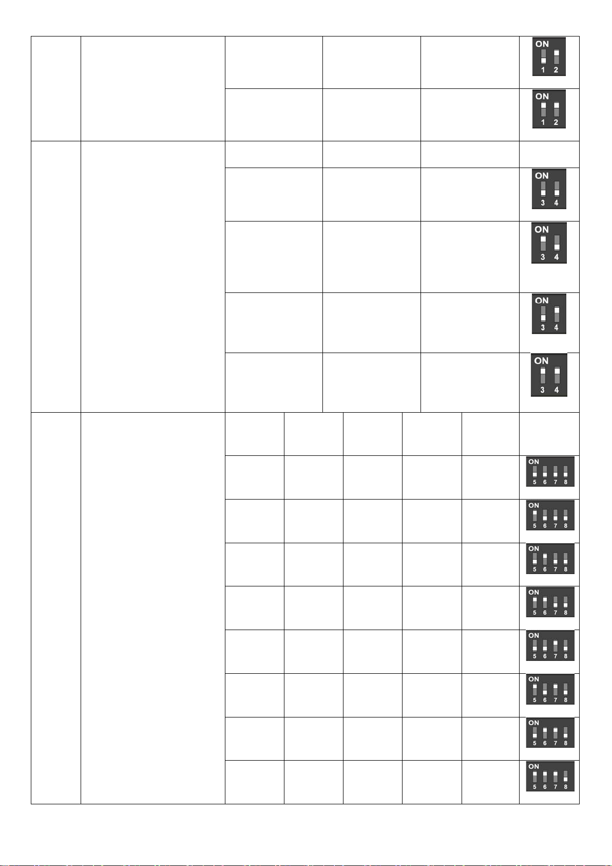
OFF
ON
3
ON
ON
4
3,4
Mode: external control,
day, night, 24/7
Regulator 3
Regulator 4
Operating mode
Scheme
OFF
OFF
RC command
only
ON
OFF
Day operation
only
OFF
ON
Night operation
only
ON
ON
24/7
5,6,7,8
Pauses between
shots
Regulator
5
Regulator
6
Regulator
7
Regulator
8
Time,
min
Scheme
OFF
OFF
OFF
OFF
1
ON
OFF
OFF
OFF
2
OFF
ON
OFF
OFF
3
ON
ON
OFF
OFF
5
OFF
OFF
ON
OFF
7
ON
OFF
ON
OFF
10
OFF
ON
ON
OFF
13
ON
ON
ON
OFF
16
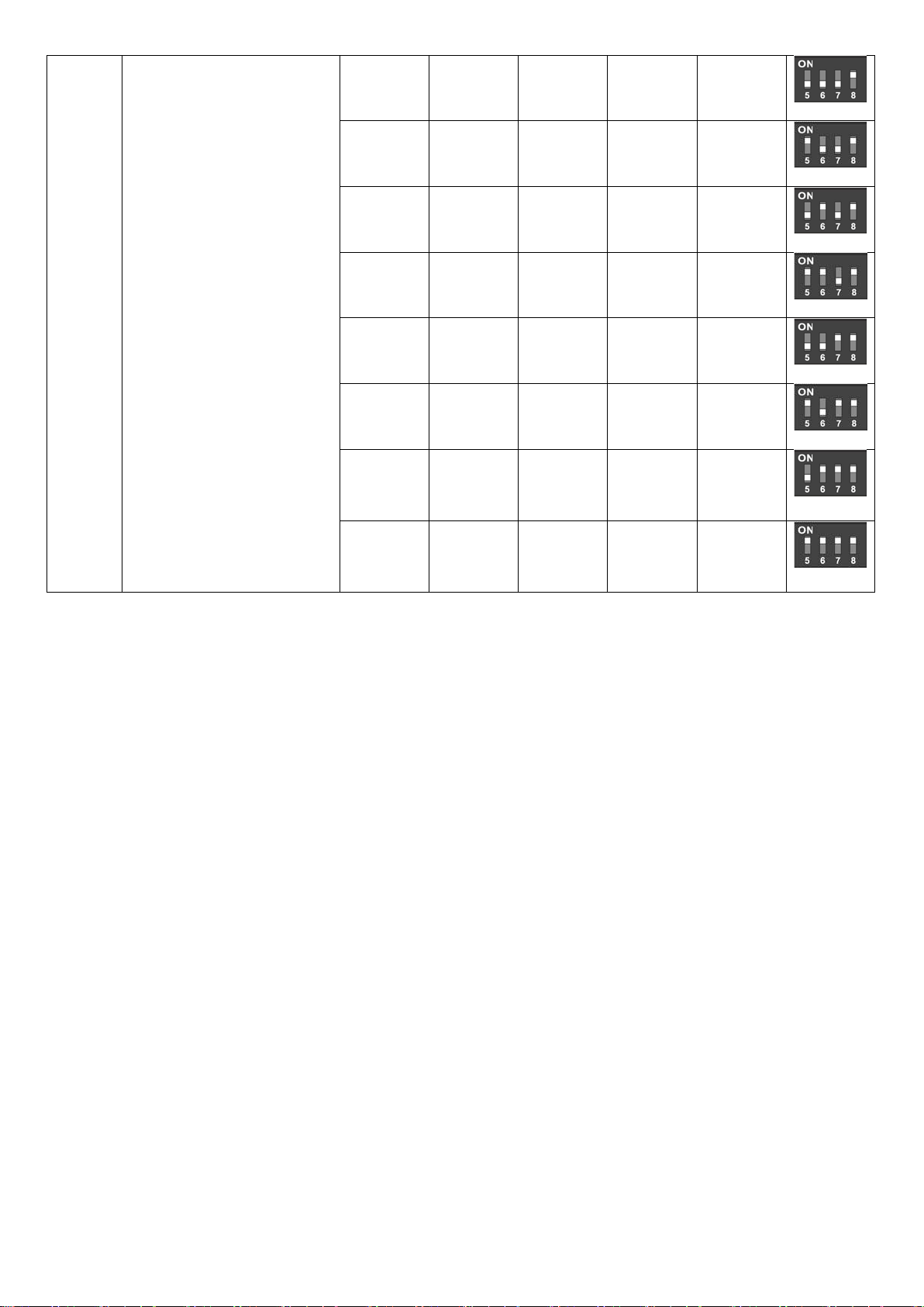
OFF
OFF
OFF
ON
20
ON
OFF
OFF
ON
25
OFF
ON
OFF
ON
30
ON
ON
OFF
ON
35
OFF
OFF
ON
ON
45
ON
OFF
ON
ON
60
OFF
ON
ON
ON
Random
(from 1 to
10 min)
ON
ON
ON
ON
Random
(from 1 to
20 min)
After setting, close the control unit cover, screw 4 screws, close the visor.
2.2.2.5 Turning on/off the device.
After the device it set, open the gas tank valve. Connect the power cable with battery terminals (brown
cable with +battery terminal, blue with –battery terminal. In case of successful connection, red LED
indicator (1, Figure 3) will light up. The device will start operation in 20 seconds (time to move away from
the device to a safe distance) according to the settings.
While operating, the gas supply LED indicator (2, Figure 3) and spark plug operation LED indicator (3,
Figure 3) will light up. Power and battery charge LED indicator (1, Figure 3) lights up in red. The device has
battery control function which stops the device operation. If battery charge is low, battery indicator flashes in
red. Replace the battery.
Manufacturer recommends to use batteries with 7Ah capacity and more. Fully charged battery with 7Ah
capacity powers the device for up to 14 days, depending on the mode. Please, provide the battery protection
from precipitation. Do not cover the light sensor (9, Figure 2).
To turn the device off, disconnect power cable from battery and close the gas tank valve.

3MAINTENANCE
Maintenance requires cleaning the device’s surface if necessary.
4TYPICAL PROBLEMS AND POSSIBLE SOLUTIONS
Typical problems and possible solutions are specified in Table 4.
Table 4
Problem
Possible reason
Possible solution
The device doesn’t make
shots when turned on.
Low battery charge.
Charge or replace a battery.
Light sensor is covered or
dirty.
Uncover or clean the light
sensor.
Incorrect settings of control
unit:
-remote control mode;
-night mode (shots at night only);
-day mode (shots in day hours
only).
Check the settings of switch
panel according to Table 3.
The gas in the tank ran out.
Refuel or replace gas tank.
The device is defective.
Take the device to service center.
5PACKAGING, STORAGE AND TRANSPORTATION
Each device is supplied in individual package according to the package content as shown in Table 1.
The device is fixed in order to prevent its moving inside the package.
Packaged devices are placed into shipping corrugated cardboard box.
Packaged devices can be transported by vehicle or railway in covered trucks or containers, or by air.

Packages should be protected from precipitation and direct sun rays during transportation.
Transportation conditions:
- Ambient air temperature: from -58 to 122 ℉(from -50 up to 50 °С);
- Relative humidity: up to 95% at 77 ℉(25 °С);
- Atmospheric pressure from 84 up to 107 kPa (630 - 800 mmHg);
- Shock acceleration peak value is up to 147 m/s² (15 g), with a duration of shock acceleration from 10 to
15 ms.
The requirements indicated on warning signs must be strictly obeyed when loading and transporting.
6 MANUFACTURER WARRANTY
6.1 The manufacturer guarantees that the product conforms to the applied requirements under the operating,
storage and transportation conditions specified in the Manual.
6.2 The device’s service life — up to 5 years.
6.3 Manufacturer warranty –12 months from the date of purchase.
6.4 If the device fails during the warranty period, the supplier (manufacturer or companies providing
maintenance services) should replace or repair it at supplier’s own expense.
6.5 Customer loses the right to obtain warranty service in the following cases:
- After warranty term expiration;
- Violation of the operation, transportation and storage instructions;
- Mechanical damages causing device failure after the purchase;
- Manufacturer seal is broken.
6.6 Repairing and maintaining of the device with an expired warranty period are covered at customer’s expense.
This manual suits for next models
1
Table of contents
Other Sititek Lawn And Garden Equipment manuals


