manuals.online logo
Brands
  1. Home
  2. •
  3. Brands
  4. •
  5. SJE Rhombus
  6. •
  7. Control Panel
  8. •
  9. SJE Rhombus 123 User manual

SJE Rhombus 123 User manual

Single Phase Duplex
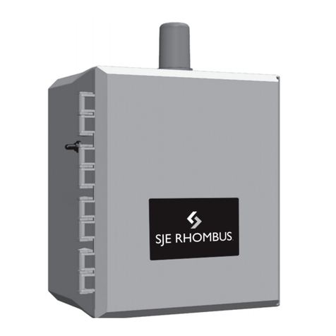
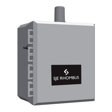
SJE-Rhombus®Type 123
Installation Instructions and Operation/Troubleshooting Manual
22650 County Highway 6
n
P.O. Box 1708
Detroit Lakes, Minnesota 56502 USA
1-888-DIAL-SJE (1-888-342-5753)
Phone: 218-847-1317
n
Fax: 218-847-4617
E--mail: customer[email protected]
Website: www.sjerhombus.com
©SJE-Rhombus
PN1009560D • Rev 11/14
Manufactured by:
Installation
Warranty void if panel is modied.
Call factory with servicing questions:
1-800-RHOMBUS
(1-800-746-6287)
This control panel must be installed and serviced by a licensed
electrician in accordance with the National Electric Code NFPA-70, state
and local electrical codes.
All conduit running from the sump or tank to the control panel must be
sealed with conduit sealant to prevent moisture or gases from entering the panel.
NEMA 4X enclosures are for indoor or outdoor use, primarily to provide
a degree of protection against corrosion, windblown dust and rain, splashing
water and hose-directed water. Cable connectors must be liquid-tight in
NEMA 4X enclosures.
Most Type 123 panels are designed to operate as three or four oat systems.
The three oat system is standard performing the common pump stop, lead
pump start, and lag pump start/high level alarm functions. The four oat system
utilizes separate oats for lag pump start and high level alarm.
NOTE: Options ordered may affect the number of oats and their func-
tions. Please reference the schematic provided with the control panel
for proper installation.
Installation of Floats
CAUTION: If control switch cables are not wired and mounted in the correct
location, the pump system will not function properly.
WARNING: Turn off all power before installing oats in pump chamber. Failure
to do so could result in serious or fatal electrical shock.
1. Use oat label kit to identify and label cables on both oat and stripped
ends (stop, lead, lag, alarm, etc.). See schematic for oat options.
2. Determine your normal operating level, as illustrated in Figures 1-2.
3. Mount oat switches at appropriate levels as illustrated in Figures 3-5.Be
sure that oats have free range of motion without touching each other, or
other equipment in the basin.
If using the mounting clamp; follow steps 4-6.
4. Place the cord into the clamp as shown in Figure 5.
5. Locate the clamp at the desired activation level and secure the clamp to
the discharge pipe as shown in Figure 5.
NOTE: Do not install cord under hose clamp.
6. Tighten the hose clamp using a screwdriver. Over tightening may result in
damage to the plastic clamp. Make sure the oat cable is not allowed to
touch the excess hose clamp band during operation.
NOTE: All hose clamp components are made of 18-8 stainless steel
material. See your SJE-Rhombus®supplier for replacements.
FIGURE 1 - Three oat duplex
(mounting clamp)
FIGURE 2 - Four oat duplex
(mounting clamp)
Mounting the control panel
1. Determine mounting location for panel. If distance exceeds
the length of either the oat switch cables or the pump power
cables, splicing will be required. For outdoor or wet installation,
we recommend the use of a SJE-Rhombus®liquid-tight junction
box with liquid-tight connectors to make required connections.
You must use conduit sealant to prevent moisture or gases
from entering the panel.
2. Mount control panel with mounting anges furnished with
control panel.
3. Determine conduit entrance locations on control panel. Check
local codes and schematic for the number of power circuits
required.
NOTE: Be sure the incoming power, voltage, amperage, and
phase meet the requirements of the pump motors being in-
stalled. If in doubt, see the pump identication plate for electrical
requirements.
4. Drill proper size holes for type of connectors being used.
NOTE: If using conduit, be sure that it is of adequate size to pull
the pump and switch cables through. You must use conduit
sealant to prevent moisture or gases from entering the
panel.
5. Attach cable connectors and/or conduit connectors to control
panel.
FOR INSTALLATION REQUIRING A SPLICE,
FOLLOW STEPS 6-10;
Installation Instructions
FIGURE 5 - Mounting clamp detail
FIGURE 3 - Internally
weighted oat
FIGURE 4 - Float with cable weight
FOR INSTALLATION WITHOUT A SPLICE,
GO TO STEP 11.
6. Determine location for mounting junction box according to local
code requirements. Do not mount the junction box inside the
sump or basin.
7. Mount junction box to proper support.
8. Run conduit to junction box. Drill proper size holes for the type
of conduit used. Attach liquid-tight connectors to junction box.
9. Identify and label each wire before pulling through conduit into
control panel and junction box. Pull pump power cables and
control switch cables through connectors into junction box.
Make wire splice connections at junction box.
10. Firmly tighten and seal all ttings on junction box. Insure all
cable connectors are liquid-tight and sealed.
11. If a junction box is not required, connect pump and oat wires
to proper position on terminals. See schematic inside control
panel for terminal layouts.
12. Connect control/alarm and pump power conductors to proper
position on terminals. See schematic inside control panel for
terminal connections.
NOTE: It is the recommendation of the factory to use separate pump
and control/alarm power sources.
VERIFY CORRECT OPERATION OF CONTROL PANEL AFTER
INSTALLATION IS COMPLETE.
Operations
SJE-Rhombus® Type 123 panels are designed to operate
with three or four oats for pump sequencing. The standard oat
functions are common pump stop, lead pump start, lag pump start/
alarm (three oats), or separate lag and alarm oats (four oats).
Three Float Operation: As the liquid level rises to the stop
oat and tips it to the ON (closed) position, the panel will remain
inactive. As the liquid level tips the lead oat, the lead pump will
start. If the liquid level tips the lag/alarm oat, the lag pump will start
and the audio/visual alarm will activate. Both pumps and the alarm
will remain active until the liquid level drops and the lag oat is in
the OFF (open) position. At this time the alarm will silence. Both
pumps will remain on until the liquid level drops to normal and all
three oats are in the OFF (open) position. When both pumps have
stopped running, the alternator will switch the lead pump and lag
pump operating functions in the next sequence.
Four Float Operation: The alarm will activate and remain on
only if the alarm oat is tipped to the ON (closed) position.
Alarm System (Horn and Indicator - standard)
When an alarm condition occurs, a red light and a horn will be
activated. If the test/normal/silence switch is moved to the silence
position, the horn will be silenced. When the alarm condition is
cleared, the alarm system is reset. The alarm system can be tested
by moving the test/normal/silence switch to the test position.
Control/Alarm Switch
Allows the control/alarm power to be turned on or off.
HOA Switch
A hand-off-automatic switch is provided for each pump. In the
hand mode, the pump will turn on unless other safety features
are employed. In the automatic mode, the pump will turn on from
commands by the oat switch(es).
Pump Run Lights
The run light will be ON in either the hand or the automatic mode
when the pump is called to run.
Control/Alarm Light
Light will illuminate when control/alarm power is supplied and the
control ON/OFF switch is in the ON position.
Float Status Lights
Lights will illuminate when the respective oat is in the closed
position.
Circuit Breaker (optional)
The pump circuit has a thermal-magnetic circuit breaker which
provides pump disconnect and branch circuit protection.
Seal Failure Circuit and Indicator Light (optional)
The seal fail circuit has resistance sensitivity and will sense the pres-
ence of water in the pump seal chamber. Upon installation, turn the
sensitivity dial to the point where the light turns on, then dial back
slowly until the light turns off. If water enters the seal chamber at this
point, the seal chamber circuit will sense the change in resistance.
After a short time delay, the indicator light will turn on. When the
condition is cleared, the relay will de-energize and the indicator light
will turn off. The seal fail relay has a sensitivity adjustment so that
false readings may be tuned out.
Dry Auxiliary Contacts (optional)
Normally open - Contacts are open under normal conditions and
closed when alarm condition is present.
Normally closed - Contacts are closed under normal conditions
and open when alarm condition is present. Both types automatically
reset once alarm condition is cleared.
Overload Relay (optional)
An overload relay is supplied in the pump circuit. The overload
must be set in the eld. Dial the amp scale to the pump full load
amps. If the full load amps are unknown, use a calibrated ammeter
to measure the pump amperage draw under loaded conditions. An
auxiliary contact from the overload is wired in series with the mag-
netic contactor coil so that on a trip, the contactor will be disabled
and will stop the pump. The overload relay must be reset on an
overload trip.
Thermal Cutout (optional)
The thermal cutout circuit is wired in series with the magnetic con-
tactor coil. If the pump’s thermal switch opens on high temperature,
the contactor will turn off and stop the pump. When the thermal
switch cools and closes, the magnetic contactor will turn on, if the
pump is called to run.
NOTE: Some options ordered may not be included in this manual.
Certain options will require alternative circuitry not including oat
status and control/alarm indicators.
Troubleshooting
Control/Alarm Circuit Board Power
If control ON/OFF switch is in the ON position but the yellow
power status indicator is not illuminated:
1. Check to see if the fuse on the circuit board is blown.
2. Check to see if the incoming control/alarm power is present
at TB1-1 and TB1-2.
If voltage is present and fuse is not blown, please call factory for
assistance.
Circuit Breaker (optional)
Check each pole of the circuit breaker for proper resistance reading
using the following procedure:
Warning: Disconnect all incoming power to control panel.
Failure to do so could result in serious or fatal electrical shock.
1. Isolate the circuit breaker by disconnecting either the line side
or load side wires.
2. Place the ohmmeter leads across the corresponding line and
load terminals of each pole.
3. With the ohmmeter on the R X 1 scale and the breaker in the
OFF position, the reading should be innity (very high resis-
tance). With the breaker in the ON position, the reading should
be nearly zero ohms (very low resistance). If the readings are
not as stated, replace the circuit breaker with one of the same
ratings.
Alarm Horn
Moving the test/normal/silence switch to the test position or activat-
ing the alarm oat should turn on the alarm horn. If the horn does
not sound, replace horn with same type.
(Troubleshooting - continuted on next page)
Alarm Light
Moving the test/normal/
silence switch to the test
position or activating the
alarm oat should turn on
the alarm light. If the light
does not activate, replace with bulb of same type.
Float Controls
Check the oats during their entire range of operation. Clean,
adjust, or replace damaged oats.
Checking the oat resistance - The oat resistance can be
measured to determine if the oat is operating correctly or is
defective. Use the following procedure to measure the float
resistance. Warning: Disconnect all incoming power to panel.
Failure to do so could result in serious or fatal electrical shock.
1. Isolate the oat by disconnecting one or both of the oat leads
from the oat terminals.
2. Place one ohmmeter lead on one of the oat wires, and the
other ohmmeter lead on the other oat wire.
3. Place the ohmmeter dial to read ohms and place on the R X
1 scale. With the oat in the “off” position, the scale should
read innity (high resistance). Replace the oat if you do not
get this reading. With the oat in the ON position, the scale
should read nearly zero (very low resistance). Replace the
oat if you do not get this reading.
NOTE: Readings may vary depending on the length of wire and
accuracy of the measuring device.
Fuses
Check the continuity of the fuse. With power OFF, pull the fuse out
of the fuse block. With the ohmmeter on the R X 1 scale, measure
resistance. A reading of innity indicates a blown fuse and must be
replaced. Replace fuse with same type, voltage and amp rating.
SJE-RHOMBUS®warrants to the original consumer that this
product shall be free of manufacturing defects for ve years after
the date of consumer purchase. During that time period and
subject to the conditions set forth below, SJE-RHOMBUS®will
repair or replace, for the original consumer, any component which
proves to be defective due to defective materials or workmanship
of SJE-RHOMBUS®.
THIS EXPRESS WARRANTY DOES NOT APPLY TO THE
MOTOR START KIT COMPONENT. SJE-RHOMBUS® MAKES
NO WARRANTIES OF ANY TYPE WITH RESPECT TO THE
MOTOR START KIT.
ELECTRICAL WIRING AND SERVICING OF THIS PRODUCT
MUST BE PERFORMED BY A LICENSED ELECTRICIAN.
THIS WARRANTY DOES NOT APPLY: (A) to damage due to
lightning or conditions beyond the control of SJE-RHOMBUS®; (B)
to defects or malfunctions resulting from failure to properly install,
operate or maintain the unit in accordance with printed instructions
provided; (C) to failures resulting from abuse, misuse, accident, or
negligence; (D) to units which are not installed in accordance with
applicable local codes, ordinances, or accepted trade practices,
and (E) to units repaired and/or modied without prior authorization
from SJE-RHOMBUS®.
Some states do not allow limitations on how long an implied warranty
lasts, so the above limitation may not apply to you. Some states do
not allow the exclusion or limitation of incidental or consequential
damages, so the above limitation or exclusion may not apply to you.
This warranty gives you specic legal rights, and you may also have
other rights which vary from state to state.
TO OBTAIN WARRANTY SERVICE: The consumer shall assume
all responsibility and expense for removal, reinstallation, and freight.
Any item to be repaired or replaced under this warranty must be
returned to SJE-RHOMBUS®, or such place as designated by
SJE-RHOMBUS®.
ANY IMPLIED WARRANTIES OF MERCHANTABILITY OR
FITNESS ARE LIMITED TO THE DURATION OF THIS WRITTEN
WARRANTY. SJE-RHOMBUS®SHALL NOT, IN ANY MANNER,
BE LIABLE FOR ANY INCIDENTAL OR CONSEQUENTIAL
DAMAGES AS A RESULT OF A BREACH OF THIS WRITTEN
WARRANTY OR ANY IMPLIED WARRANTY.
IEC Contactor Coil
Warning: Disconnect all incoming power to panel. Failure to do
so could result in serious or fatal electrical shock. Check the coil
by disconnecting one of the coil leads. Measure the coil resistance
by setting the ohmmeter on the R X 1 scale. A defective coil will
read zero or innity, indicating a short or opened coil respectively.
Replace defective contactor with same type.
Start and Run Capacitor
A failed capacitor will have a bulged enclosure, leading oil or a burnt
smell. Using the following procedure, check the capacitor with an
ohmmeter to determine if the capacitor is defective.
1. With the power OFF, discharge capacitor by shorting both
terminals with an insulated handle metal screwdriver.
2. Label and remove the wires from the capacitor.
3. Set the ohmmeter on the R X 10,000 (10K) scale. Place an
ohmmeter lead on each capacitor lead.
4. If the capacitor is good, the ohmmeter needle will go towards
zero and then drift slowly toward innity. If you do not get this
reading, replace capacitor with one of the same type.
NOTE: If the capacitor is checked a second time, be sure to reverse
the ohmmeter leads to get a correct ohm reading.
Start Relay
1. With power OFF, disconnect and label the wires going to the
start relay.
2. To check coil resistance, set the ohmmeter to the R X 1,000
scale. A reading of zero ohms indicates a defective relay.
3. When checking contact resistance, a reading other than
zero indicates a defective relay. (See schematic for relay pin
numbers.)
SJE-Rhombus®Five-Year Limited Warranty
Troubleshooting
NOTICE!
Products returned must be cleaned, sanitized, or decontaminated as necessary prior to shipment to ensure that employees
will not be exposed to health hazards in handling said material. All applicable laws and regulations shall apply.

Other SJE Rhombus Control Panel manuals

SJE Rhombus 115 Operation and maintenance manual

SJE Rhombus

SJE Rhombus 115 Operation and maintenance manual

SJE Rhombus 122 User manual

SJE Rhombus

SJE Rhombus 122 User manual

SJE Rhombus WellZone User manual

SJE Rhombus

SJE Rhombus WellZone User manual

SJE Rhombus Three Phase Duplex User manual

SJE Rhombus

SJE Rhombus Three Phase Duplex User manual

SJE Rhombus H2O Drive RD150 User manual

SJE Rhombus

SJE Rhombus H2O Drive RD150 User manual

SJE Rhombus VS21-10.0-N3RD User manual

SJE Rhombus

SJE Rhombus VS21-10.0-N3RD User manual

SJE Rhombus IFS User manual

SJE Rhombus

SJE Rhombus IFS User manual

SJE Rhombus Installer Friendly Series User manual

SJE Rhombus

SJE Rhombus Installer Friendly Series User manual

SJE Rhombus TimeZone Troubleshooting guide

SJE Rhombus

SJE Rhombus TimeZone Troubleshooting guide

SJE Rhombus 124 User manual

SJE Rhombus

SJE Rhombus 124 User manual

SJE Rhombus 112 Operation and maintenance manual

SJE Rhombus

SJE Rhombus 112 Operation and maintenance manual

SJE Rhombus NEMA 4X User manual

SJE Rhombus

SJE Rhombus NEMA 4X User manual

SJE Rhombus EZS User manual

SJE Rhombus

SJE Rhombus EZS User manual

SJE Rhombus Installer Friendly Series User manual

SJE Rhombus

SJE Rhombus Installer Friendly Series User manual

SJE Rhombus In-Site EZ Series User manual

SJE Rhombus

SJE Rhombus In-Site EZ Series User manual

SJE Rhombus 123 User manual

SJE Rhombus

SJE Rhombus 123 User manual

Popular Control Panel manuals by other brands

Balboa Water Group Clearwater Spas spaTouch BP Series User Interface and Programming Reference Manual

Balboa Water Group

Balboa Water Group Clearwater Spas spaTouch BP Series User Interface and Programming Reference Manual

Chamberlain 935C owner's manual

Chamberlain

Chamberlain 935C owner's manual

Newport Azure user manual

Newport

Newport Azure user manual

Secutron MR-2300 series Installation and operation manual

Secutron

Secutron MR-2300 series Installation and operation manual

Pentair INTELLICENTER Quick reference guide

Pentair

Pentair INTELLICENTER Quick reference guide

Pyronix STERLING 10 user manual

Pyronix

Pyronix STERLING 10 user manual

Milesight LoRaWAN WS136 user guide

Milesight

Milesight LoRaWAN WS136 user guide

ILLUMINO IGNIS SMARTWIRE quick start guide

ILLUMINO IGNIS

ILLUMINO IGNIS SMARTWIRE quick start guide

CEStronics WT-M-I Operating	 instruction

CEStronics

CEStronics WT-M-I Operating instruction

Lofa CANplus 750 Operation and Troubleshooting

Lofa

Lofa CANplus 750 Operation and Troubleshooting

Radionics D9024 manual

Radionics

Radionics D9024 manual

Frick QUANTUM LX Control Panel Operation

Frick

Frick QUANTUM LX Control Panel Operation

Satel PERFECTA-IP user manual

Satel

Satel PERFECTA-IP user manual

Panasonic AWRP301 - PAN/TILT CONTROL PAN operating instructions

Panasonic

Panasonic AWRP301 - PAN/TILT CONTROL PAN operating instructions

Ziton ZP3 Installation operation & maintenance

Ziton

Ziton ZP3 Installation operation & maintenance

Lifasa SV030iH-2U manual

Lifasa

Lifasa SV030iH-2U manual

Lite-Puter ECP-110T user manual

Lite-Puter

Lite-Puter ECP-110T user manual

Bauer LOGICM installation manual

Bauer

Bauer LOGICM installation manual

manuals.online logo
manuals.online logoBrands
  • About & Mission
  • Contact us
  • Privacy Policy
  • Terms and Conditions

Copyright 2025 Manuals.Online. All Rights Reserved.