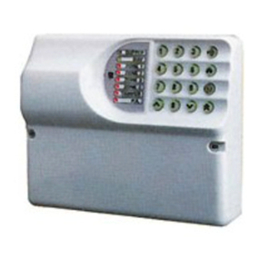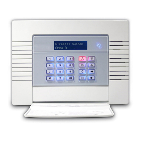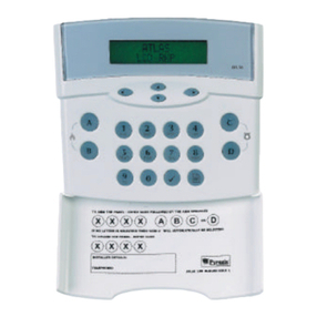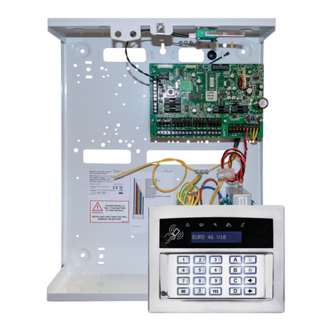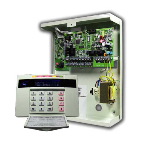
EURO 162/280 Installation Manual
Page: 2
Contents Page
Contents Page ............................................................................................................................................ 2
1. System Overview .................................................................................................................................... 3
1.1 System Overview................................................................................................................................ 3
1.2 The Devices ....................................................................................................................................... 4
1.3 EURO Input Mapping Overview: ............................................................................................................ 7
1.4 Output Mapping Overview.................................................................................................................... 9
2. Installation ............................................................................................................................................11
3. The Printed Circuit Board.........................................................................................................................12
3.1 Technical Specification .......................................................................................................................13
3.2 Important Installation Notes................................................................................................................14
3.3 Communication ATE Loom ..................................................................................................................15
3.4 Battery Connection ............................................................................................................................15
3.5 AC Mains Supply Connection ...............................................................................................................16
3.6 Engineer Keypad Connection ...............................................................................................................17
4. Input Connections ..................................................................................................................................17
4.1 Default Grade 2 DEOL (Double End of Line) Input Wiring .........................................................................18
4.2 Grade 3 Mask/Fault Input Wiring..........................................................................................................18
5. iD Wiring...............................................................................................................................................19
5.1 iD Connectors ...................................................................................................................................19
5.2 Connecting iD Biscuits to PIRs (Grade 2) ...............................................................................................20
5.1 Connecting iD Biscuits to PIRs (Grade 3) ...............................................................................................20
5.2 iD Termination ..................................................................................................................................21
5.3 iD Commissioning Readings.................................................................................................................22
5.4 Important Notes for Installing iD systems..............................................................................................22
6. Output (PGM) Connections.......................................................................................................................23
6.1 Negative Applied Wiring......................................................................................................................23
6.2 Positive Applied Wiring .......................................................................................................................23
7. External Sounder Connections ..................................................................................................................24
7.1 Grade 3 External Sounder Wiring .........................................................................................................24
7.2 Grade 2 External Sounder Wiring with a Grade 3 Bell ..............................................................................24
7.3 Grade 2 External Sounder Wiring .........................................................................................................25
8. Connecting the EURO Peripherals..............................................................................................................26
8.1 Connecting The LCD Keypad (EURO-LCD)..............................................................................................26
8.2 Connecting The Internal Tag Reader (EURO-PROXI)................................................................................29
8.3 Connecting The External Proximity Reader (EURO-PROXE).......................................................................31
8.4 Connecting The Zone Expander Module (EURO-ZEM8).............................................................................34
8.5 Connecting The Zone Expander Module with 4 PGMs (EURO-ZEM8+).........................................................37
8.6 Connecting The Zone Expander Module with PSU (EURO-ZEM8+PSU)........................................................41
8.7 Connecting The Enforcer Wireless Zone Expander Module (EURO-ZEM32-WE).............................................45
8.8 Connecting The Output Expander Module (EURO-OEM8R8T).....................................................................47
8.9 Connecting The Output Expander Module with PSU (EURO-OEM16R+PSU) .................................................49
9. The Inovonics Radio Expander..................................................................................................................51
9.1 The Inovonics Radio Expander .............................................................................................................51
9.2 The Inovonics Radio PIR .....................................................................................................................51
9.3 Addressing the Radio Expander............................................................................................................51
9.4 Assigning Radio Detectors...................................................................................................................52
9.5 Deleting Radio Detectors ....................................................................................................................52
9.6 Display the Signal Strength.................................................................................................................52
9.7 Assigning Repeaters to the Expander....................................................................................................52
9.8 Supervision Time...............................................................................................................................52
9.9 Problem Solving ................................................................................................................................53
9.10 Technical Specification......................................................................................................................53
10. The EURO-073-ARM Modem ...................................................................................................................54
10.2 Connecting to the Upload/Download Software ......................................................................................56
11. System expansion and enhancement .......................................................................................................59
11.1 Inserting the MSX Card.....................................................................................................................59
12. Access Levels.......................................................................................................................................59
Default User Code: 1234
Default Master Manager: 2222
Default Engineer Code: 1111
