SKF K Series Instruction Manual

User and maintenance instructions
Model , series “K”
Air operated grease pump
Date of issue October 2022
Form number 402819
Version 2

Contents
Declaration of Incorporation* . . . . . . . 3
U.K. Declaration of Incorporation* . . . 4
Safety* . . . . . . . . . . . . . . . . . . . . . . . . . . 5
Signal words for safety. . . . . . . . . . . . . 5
Specifications . . . . . . . . . . . . . . . . . . . . .
To fill reservoir . . . . . . . . . . . . . . . . . . . 6
To prime system . . . . . . . . . . . . . . . . . . 6
Supply lines: . . . . . . . . . . . . . . . . . . . . . .
Feeder lines: . . . . . . . . . . . . . . . . . . . . . .
Injectors: . . . . . . . . . . . . . . . . . . . . . . . . .
Operation of the pump . . . . . . . . . . . . . 7
What to do if . . . . . . . . . . . . . . . . . . . . . 7
Service parts. . . . . . . . . . . . . . . . . . . . . .
Types of installations . . . . . . . . . . . . . . 11
Mechanical control . . . . . . . . . . . . . . . . .
Electrical control . . . . . . . . . . . . . . . . . . .
Manual control . . . . . . . . . . . . . . . . . . . .
Warranty . . . . . . . . . . . . . . . . . . . . . . . . .
*Indicates change.

Declaration of Incorporation* DOCUMENT NUMBER
402819.DoI
Manufacturer name/address:
Lincoln Industrial Corporation
N. Hanley Road
St. Louis, MO U.S.A.
TEL: + () - FAX: + () -
Authorized to compile the technical file:
SKF Lubrication Systems Germany GmbH
Heinrich-Hertz-Straße -
Walldorf, Germany
TEL: + () -
EMAIL: robert.collins@skf.com WEBSITE: www.skf.com
This Declaration of Incorporation is issued
under sole responsibility of the
manufacturer. Lincoln Industrial Corporation
hereby declares that the partly completed
machinery stated below:
Name: RAM pumps
Model number(s):
Description:
Year of CE:
in its intended use, is in conformity with the
relevant union harmonization legislation:
Machinery Directive //EC
and conforms to the following harmonized
standards:
EN ISO :
Hydraulic fluid power - General rules and
safety requirements for systems and their
components
EN ISO :
Safety of machinery. General principles
for design. Risk assessment and risk
reduction
EN ISO :
Pneumatic fluid power. General rules and
safety requirements for systems and their
components
EN ISO :+A:
Pumps and pump units for liquids -
Common safety requirements
EN :+A:
Safety of machinery – Minimum gaps to
avoid crushing of parts of the body
I, the undersigned of Lincoln Industrial Corporation, do hereby declare that the that the partly completed machinery described above above,
in its intended use, conforms to the requirements of the above EC Directive(s).
___________________________________
Robert Collins
Technical Compliance Manager
St. Louis, MO, U.S.A.
The following EHSR (Essential Health and
Safety Requirements) have been applied:
..a - ..b - ..c - .. - .. -
.. - .. - .. - .. - .. - ..
- .. - . - .. - ... - .. - ..
The manufacturer maintains a technical file
summary sheet containing test reports and
product documentation:
Technical file summary sheet number:
The partly completed machinery shown
above should not be put into service until the
final machinery into which it is to be
incorporated has been declared in conformity
with the provisions of the directive, where
appropriate.
(series K)
Air operated pumps
RA-
// *Indicates change.

*Indicates change.
U.K. Declaration of Incorporation* DOCUMENT NUMBER
UK402819CA
Manufacturer name/address:
Lincoln Industrial Corporation
N. Hanley Road
St. Louis, MO U.S.A.
TEL: + () - FAX: + () -
Authorized to compile the technical file:
SKF (U.K.) Limited
Canada Close
Banbury, Oxfordshire, OX RT, GBR
EMAIL: robert.collins@skf.com WEBSITE: www.skf.com
This U.K. Declaration of Incorporation is
issued under sole responsibility of the
manufacturer. Lincoln Industrial Corporation
hereby declares that the partly completed
machinery stated below:
Name: RAM pumps
Model number(s):
Description:
Year of CE:
in its intended use, is in conformity with the
relevant union harmonization legislation:
Supply of Machinery (Safety) Regulations
(S.I. :)
along with the following Directive(s) that
were also applied with the above legislation:
EN ISO :
Hydraulic fluid power - General rules and
safety requirements for systems and their
components
EN ISO :
Safety of machinery. General principles
for design. Risk assessment and risk
reduction
EN ISO :
Pneumatic fluid power. General rules and
safety requirements for systems and their
components
EN ISO :+A:
Pumps and pump units for liquids -
Common safety requirements
EN :+A:
Safety of machinery – Minimum gaps to
avoid crushing of parts of the body
I, the undersigned of Lincoln Industrial Corporation, hereby declare that the that the partly completed machinery described above above, in
its intended use, conforms with the Essential Health and Safety Requirements of U.K. legislation Supply of Machinery (Safety) Regulations
No. Annex I, Declaration of Incorporation by the time of placing it on the market.
___________________________________
Robert Collins
Technical Compliance Manager
St. Louis, MO, U.S.A.
The following EHSR (Essential Health and
Safety Requirements) have been applied:
..a - ..b - ..c - .. - .. -
.. - .. - .. - .. - .. - ..
- .. - . - .. - ... - .. - ..
The manufacturer maintains a technical file
summary sheet containing test reports and
product documentation:
Technical file summary sheet number:
The partly completed machinery shown
above should not be put into service until the
final machinery into which it is to be
incorporated has been declared in conformity
with the provisions of the directive, where
appropriate.
(series K)
Air operated pumps
RA-
//

*Indicates change.
Safety*
The assembly must be installed, maintained
and repaired exclusively by persons familiar
with the instructions.
Always disconnect power source
(electricity, air or hydraulic) from the
equipment when it is not being used.
This equipment generates high pressure.
Extreme caution should be used when
operating this equipment as material leaks
from loose or ruptured components can
inject fluid through the skin and into the
body. If any fluid appears to penetrate the
skin, seek attention from a doctor
immediately. Do not treat injury as a simple
cut. Tell attending doctor exactly what type of
fluid was injected.
Any other use not in accordance with
instructions will result in loss of claim for
warranty or liability.
• Do not misuse, over-pressurize, modify
parts, use incompatible chemicals, fluids,
or use worn and/or damaged parts.
• Do not exceed the stated maximum
working pressure of the equipment or of
the lowest rated component in your
system.
• Always read and follow the manufacturer’s
recommendations regarding fluid
compatibility, and the use of protective
clothing and equipment.
• Failure to comply may result in personal
injury and/or damage to equipment.
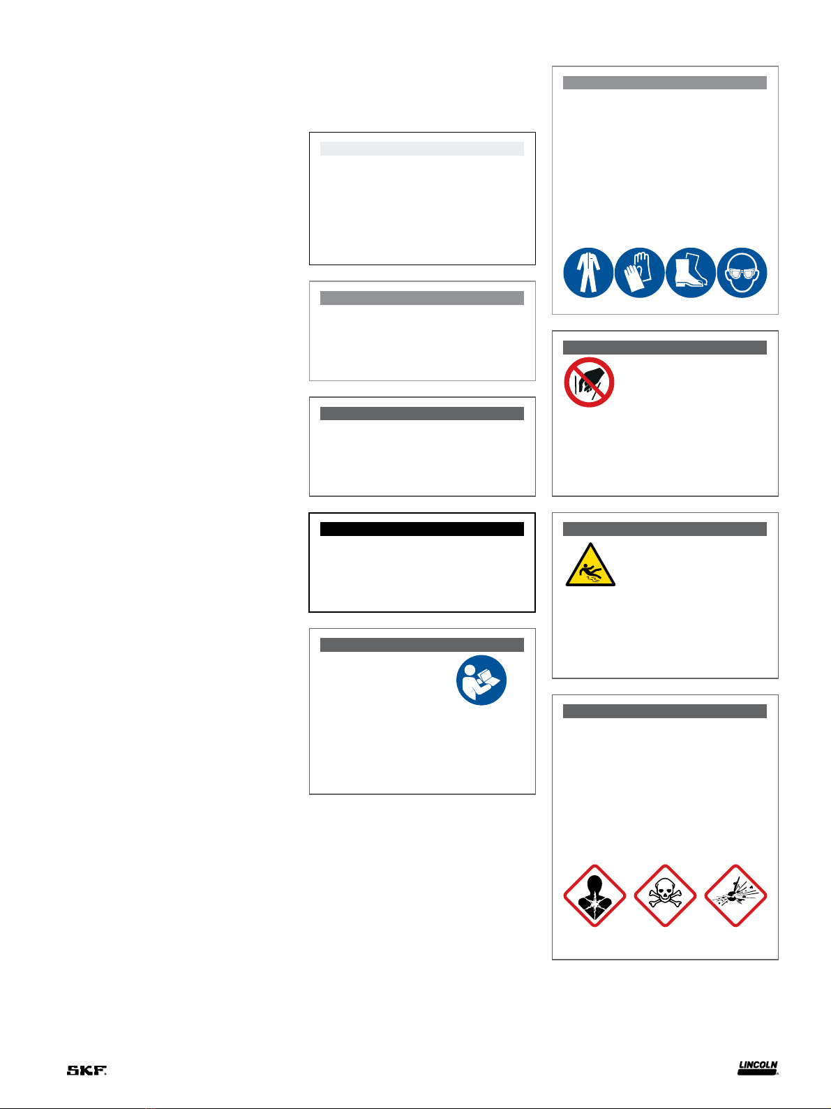
CAUTION
Do not operate equipment without
wearing personal protective gear.
Wear eye protection. Protective
equipment such as dust mask, non-skid
safety shoes, hard hat, or hearing pro-
tection used for appropriate conditions
will reduce personal injuries.
Failure to comply may result in light
personal injury.
WARNING
Do not allow any body part
to be trapped by equipment.
Body parts can be crushed
by subassemblies during
operation.
Failure to comply may result in death
or serious physical injury.
WARNING
Do not allow fluid to leak
onto floor when operating
equipment. If spill occurs,
clean any fluid on floor before continuing
operation.
Failure to comply may result in death
or serious personal injury.
WARNING
Do not use this equipment to supply,
transport, or store hazardous
substances and mixtures in accordance
with annex I part - of the CLP
regulation (EG /) or HCS
CFR . marked with GHS,
GHS and GHS hazard pictograms
shown:
Explanation of signal words
for safety
NOTE
Emphasizes useful hints and
recommendations as well as
information to prevent property damage
and ensure efficient trouble-free
operation.
CAUTION
Indicates a dangerous situation that can
lead to light personal injury if
precautionary measures are ignored.
WARNING
Indicates a dangerous situation that
could lead to death or serious injury if
precautionary measures are ignored.
DANGER
Indicates a dangerous situation that will
lead to death or serious injury if
precautionary measures are ignored.
WARNING
Do not operate
equipment without
reading and fully
understanding safety
warnings and instructions.
Failure to follow warnings and
instructions may result in serious injury.

Fig. 2
Specifications
Lubricant operationg presure
Ratio
Output per
stroke
Reservoir
capacity Air inlet
Lubricant
outlet
Type of
syste. Minimum Maximum Recommended
: . in
(7.4 cm3)
lb
(492 cm3)
1/4in NPT (F) 1/4in NPT (F) SL- psi with
psi air
(82 bar with
4.1 bar air)
psi with
psi air
(241 bar with
12 bar air)
psi with
psi air
(103 psi with
5.2 bar air)
: . in
(7.4 cm3)
lb
(492 cm3)
1/4in NPT (F) 1/4in NPT (F) SL- psi with
psi air
(82 bar with
4.1 bar air)
psi with
psi air
(241 bar with
12 bar air)
psi with
psi air
(103 psi with
5.2 bar air)
) Based on lubricants that are free from entrapped air. Lubricants that are aerated will reduce output of pump.
The pump is used as the pumping
unit for a centralized lubrication system hav-
ing a single line circuit of SL- or SL-
injectors. It is an air-operated, single-stroke,
spring-return pump that discharges
. in(7.4 cm3)into the circuit for each
pump cycle.
The total quantity of lubricant needed for
the lubrication cycle of the system must not
exceed the lubricant discharged per pump
stroke.
To fill reservoir
Use manual filler pump to fill reser-
voir through the filler fitting in the pump
body. Attach coupler on delivery hose to filler
fitting. Stroke filler pump handle until lubri-
cant weepage is noted at air vent hole in the
reservoir (lower portion of follower must rise
beyond air vent hole to expel entrapped air
from lubricant).
To prime system
Supply lines:
After pump reservoir has been filled with
recommended lubricant, loosen (do not
remove) all plugs in dead ends of the injector
manifolds and supply lines. Operate pump
until lubricant flows from around threads of
any loosened plug. Tighten this plug and
continue to operate pump until lubricant
flows from around threads of another loos-
ened plug. Repeat this procedure until all
supply lines are primed and all plugs are
securely tightened.
Feeder lines:
Fill each feed line with lubricant before
connecting lines to outlet of injectors and
bearings. This will prevent having to cycle
each injector to fill line between injector and
bearing.
Injectors:
Check each Injector for proper operation.
Injector stem moves when injector
discharges lubricant to bearing. This may
require cycling system several times.
After checking injectors for operation adjust
injectors for the volume required for each
bearing.
NOTE
When filling the reservoir, caution
should be used as extreme pressure can
cause damage to reservoir and follower
assembly.

Operation of the
pump
Lubricant in the translucent reser-
voir flows into the cavity in the bush-
ing and plunger assembly.
Compressed air entering the bottom of
the air cylinder [1/4in NPT (i)] moves
the piston upward. As the piston
moves upward, the plunger is also moved
upward into the bushing. As the plunger
moves upward, it moves the charge of lubri-
cant from the bushing cavity through the
outlet check to the outlet of the pump.
When the air pressure to the air
cylinder is relieved, the piston spring
moves the piston and plunger downward.
In its extreme down position, the plunger
has retracted below the bushing port,
permitting lubricant to flow into the bushing
cavity.
What to do if
Pump loses prime.
Check lubricant supply.
System fails to cycle and
calculated system planning has
been followed.
Lubricant may be leaking by the ball
check or the packing in the
check and vent assembly. Remove these
parts and examine for presence of foreign
particles. Clean, or replace parts if worn or
damaged.
Pump fails to operate.
Check air supply. Failure of injectors to cycle
can be caused by a leak in the supply line.
NOTE
Pump must be installed in a vertical
postion.
NOTE
In reassembling the check and
extension assembly, the vent pressure
must be reset. Vent pressure can be
varied by the adjusting screw .
The recommended pressure setting is
psi (1,7 bar) minimum to
psi (5,2 bar) maximum. An improper
setting will affect the pump efficiency.
Assemble with nonhardening
threadlocker or stake threads after
adjusting vent pressure.

Fig. 3

Service parts
Part no Description Quantity Part no Description Quantity
Ball stop ) Spring
Check body ) Ball
Bushing Retaining ring
Bushing Plug bottom
) Gasket ) Filter
) Gasket Check assembly
) O-ring (Nitrile) Cylinder end
) Gasket (Neoprene) Reservoir (Acrylic)
) O-ring (Nitrile) Cylinder casting
) Gasket Screw
) Packing (Nitrile) Piston
Cover cap Spring
Washer ) U-cup (Nitrile)
Nut Bushing and plunger
Spring ) O-ring (Nitrile)
) These components available as repair kit.

Fig. 4

Fig. 5
Fig. 6
Types of installations
Frequency of lubrication cycle can be con-
trolled mechanically, electrically or manually.
Mechanical control
When using mechanical motion of machine
to control lubrication frequency, three way
valve is engaged by cam, permitting air to
pass through valve to pump, forcing air pis-
ton forward and lubricant through supply
line to injectors. When the valve is disen-
gaged, air exhausts back through valve, and
spring in pump returns air piston, complet-
ing lubrication cycle. Cam dwell on three way
valve must be arranged for a minimum of
seconds.
When mechanical motion of machine is
too rapid to be used as a source of control for
frequency of lubrication cycle, a cycle timer
with adjustable settings may be used. See
separate instructions for cycle timer .
Electrical control
Electrical time switch opens three way sole-
noid valve, permitting air to flow to pump
forcing air piston forward and lubricant
through supply line to injectors. When valve
closes, air exhausts back through valve, and
spring in pump returns air piston, complet-
ing lubrication cycle. Frequency of cycle can
be set by time switch.

Fig. 7
Manual control
Opening three way valve for a minimum of
seconds permits air to flow to pump forc-
ing air piston forward and lubricant through
supply line to injectors. When valve is closed,
air exhausts back through valve, and spring
in pump returns air piston, completing lubri-
cation cycle.

This page left intentionally blank.

This page left intentionally blank.

This page left intentionally blank.

skf.com | lincolnindustrial.com
® SKF and Lincoln are registered trademarks of the SKF Group.
© SKF Group
The contents of this publication are the copyright of the publisher and may not be reproduced (even
extracts) unless prior written permission is granted. Every care has been taken to ensure the accuracy
of the information contained in this publication but no liability can be accepted for any loss or damage
whether direct, indirect or consequential arising out of the use of the information contained herein.
October · Form Version
Warranty
The instructions do not contain any information on the warranty.
This can be found in the General Conditions of Sales, available at:
www.lincolnindustrial.com/technicalservice or www.skf.com/lubrication.
This manual suits for next models
1
Table of contents
Other SKF Water Pump manuals
Popular Water Pump manuals by other brands

Oase
Oase ProfiClear Classic operating instructions

KSB
KSB Amar-Drainer 303.2 operating instructions

ITT
ITT Goulds Pumps 3298 Series Installation, operation and maintenance manual

Agilent Technologies
Agilent Technologies X3500-64000 user manual

Goulds Pumps
Goulds Pumps SVT-1SV Technical manual

Espa Leader
Espa Leader MISTRAL KIT L instruction manual

Danfoss
Danfoss H1P 045 Service manual

Speck
Speck P52/30-500MS operating instructions

Red Sea
Red Sea ReefDose 2 user manual

BRINKMANN PUMPS
BRINKMANN PUMPS FH11 Series operating instructions

Industrial Scientific
Industrial Scientific Ventis 17154524-1 Field guide

ITT Industries
ITT Industries HYDROVAR Smart operating instructions