5
Table of contents
Masthead ...............................................................................................4
Table of contents..................................................................................5
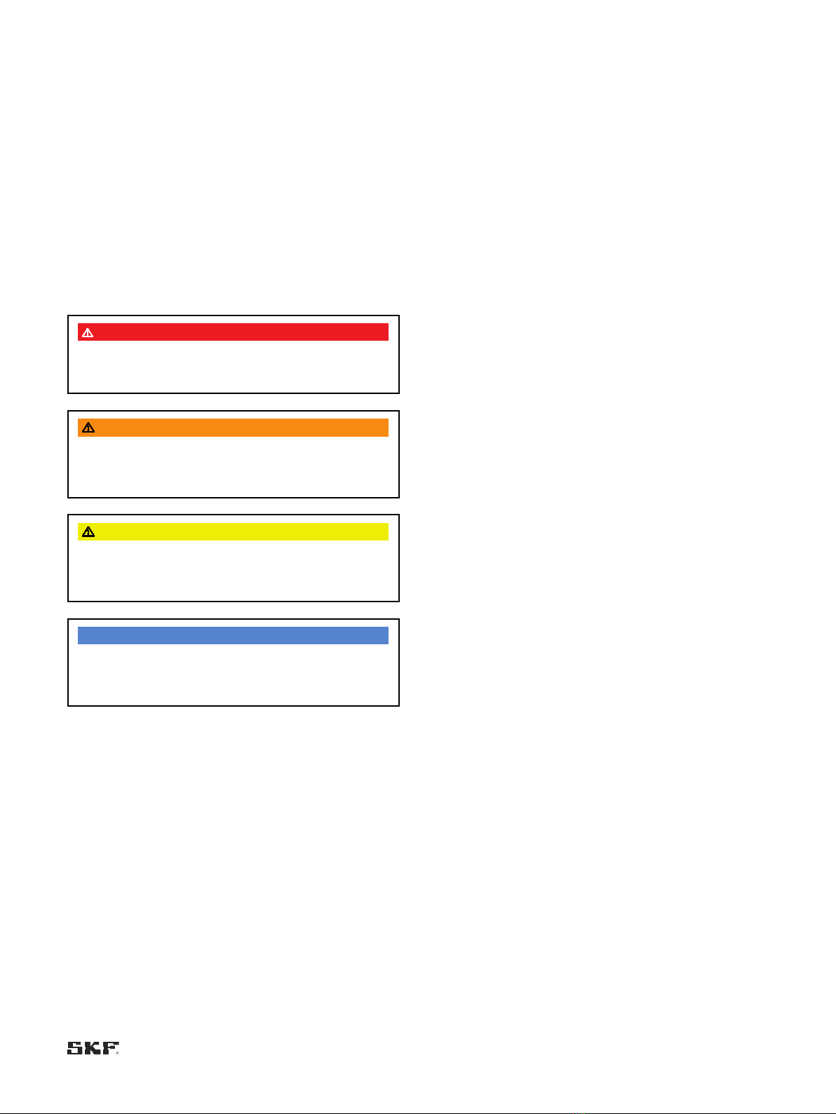
Safety alerts, visual presentation, and layout.................................7
1. Safety instructions...........................................................................8
1.1 General safety instructions......................................................8
1.2 General electrical safety instructions.....................................8
1.3 General behaviour when handling the product ...................9
1.4 Intended use...............................................................................9
1.5 Persons authorized to use the product.................................9
1.6 Foreseeable misuse ..................................................................9
1.7 Referenced documents ......................................................... 10
1.8 Prohibition of certain activities ............................................ 10
1.9 Painting plastic components and seals .............................. 10
1.10 Safety markings on the product ....................................... 10
1.11 Note on the type plate ........................................................11
1.12 Notes on CE marking .......................................................... 11
1.13 Note on Low Voltage Directive.......................................... 11
1.14 Note on Pressure Equipment Directive........................... 11
1.15 Note on UKCA marking.......................................................11
1.16 Note on UL mark .................................................................11
1.17 Note on ECE mark ...............................................................11
1.18 Note on EAC marking.......................................................... 11
1.19 Note on China RoHS mark................................................. 11
1.20 Emergency shutdown ......................................................... 11
1.21 Assembly, maintenance, fault, repair............................... 12
1.22 First start-up, daily start-up.............................................. 12
1.23 Residual risks........................................................................ 13
2. Lubricants ...................................................................................... 14
2.1 General information............................................................... 14
2.2 Material compatibility ............................................................ 14
2.3 Temperature properties........................................................14
2.4 Aging of lubricants .................................................................14
2.5 Avoidance of faults and hazards.......................................... 14
2.6 Solid lubricants ....................................................................... 14
3. Overview, functional description................................................ 15
3.1 General..................................................................................... 15
3.2 Design.......................................................................................15
3.2.1 Pump housing............................................................. 15
3.2.2 Lubricant reservoir .................................................... 15
3.2.3 Fill level monitoring ................................................... 15
3.2.4 KFGS and KFGL control units .................................. 15
3.3 Overview ..................................................................................16
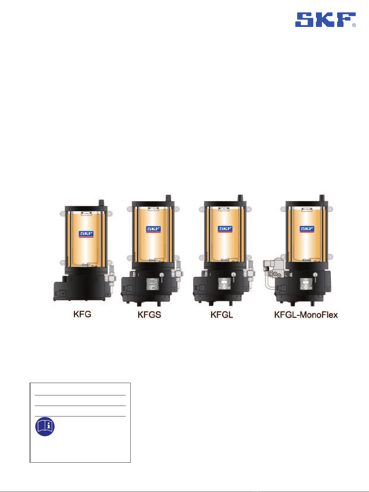
3.3.1 KFG pump units.......................................................... 16
3.3.2 KFGS pump units....................................................... 16
3.3.3 KFGL pump units ....................................................... 16
3.4 Functional description in progressive systems................. 17
3.4.1 KFG pump unit............................................................ 17
3.4.2 Progressive system with a KFGS or KFGL pump
unit ..........................................................................................19
3.5 Functional description in single-line systems................... 20
3.5.1 KFG-Pump unit with grease follower plate
technology.............................................................................. 20
3.5.2 Single-line system with a KFGL pump unit .......... 22
4. Accessories..................................................................................... 23
5. Technical data ............................................................................... 25
5.1 General technical data...........................................................25
5.2 Nominal delivery rates ..........................................................26
5.3 Pressure limiting valve..........................................................27
5.4 Pressure relief valve with integrated pressure limiting
valve .................................................................................................29
5.5 Lubricant level switch............................................................29
5.6 Type identification code for pump KFG..............................30
6. Delivery, returns, storage............................................................ 31
6.1 Delivery.....................................................................................31
6.2 Return shipment.....................................................................31
6.3 Storage..................................................................................... 31
6.4 Storage temperature range .................................................31
6.5 Storage conditions for products filled with lubricant....... 31
6.5.1 Storage period up to 6 months...............................31
6.5.2 Storage period between 6 and 18 months........... 31
6.5.3 Storage period more than 18 months................... 31
7. Assembly ........................................................................................ 32
7.1 General safety instructions................................................... 32
7.2 Mechanical connection ..........................................................32
7.2.1 Minimum mounting dimensions .............................32
7.2.2 Setup and attachment ..............................................33
7.2.3 Mounting diagram......................................................34
7.2.4 KFG dimensions.......................................................... 35
7.2.5 KFGL/KFGS dimensions ............................................35
7.3 Pump elements of the KFG series.......................................36
7.3.1 Pump element designs .............................................37
7.3.2 Installing a pump element with spring-return
piston ......................................................................................37
7.3.3 Assembly of a pump element with positively driven
pistons.....................................................................................38
7.3.4 Pressure limiting valve (DBV) ..................................39
7.4 Filling with lubricant...............................................................39
7.4.1 Filling via fill connection............................................39
7.4.2 Filler coupling..............................................................40
7.4.3 Filling cylinder.............................................................40
7.5 Power supply...........................................................................41
7.5.1 General conditions for electrical connections ....... 41
7.5.2 KFG power supply...................................................... 42
7.5.3 KFGS/KFGL power supply.........................................42
7.6 Control port assignments ..................................................... 43
7.6.1 KFG series (external control)....................................43
7.6.2 KFGS series (integrated control) .............................43
7.6.3 KFGL series .................................................................47
7.6.4 Pressure relief valve with integrated pressure
limiting valve.......................................................................... 49
7.6.5 Fill level monitoring ...................................................49
7.7 Pump unit fill level control.................................................... 51
7.8 Connection of the lubrication line........................................52
8. First start-up................................................................................. 53
8.1 Inspections before first start-up..........................................53
8.2 Inspections during first start-up..........................................53
8.3 Progressive system ventilation............................................ 54
8.4 Single-line system ventilation..............................................54
9. Operation........................................................................................ 55
9.1 KFGS control unit ................................................................... 55
9.1.1 Display and control elements of control screen... 55
9.1.2 KFGS display mode....................................................58
9.1.3 KFGS programming mode........................................60
9.1.4 KFGS operating modes .............................................65