SKF PTL User manual

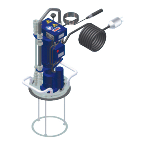
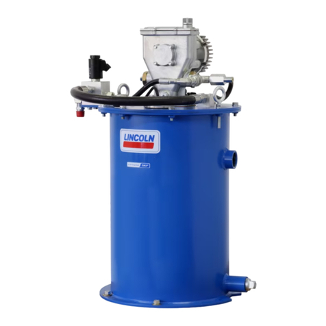
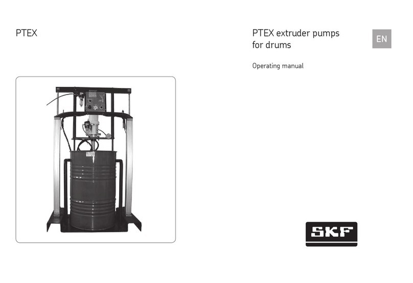
Drum pump PTL
with control cabinet
Operating manual
Version 01
Date of issue February 2017
Publication number 951-130-418-1
Languages EN
Country/Countries EN...


Imprint
In accordance with the EU Machine Directive
2006/42/CE, the installation and activation
instructions are an integral part of the prod-
uct and must be kept close to the equipment
for future reference.
The original installation and activation in-
structions were drafted in compliance with
the applicable standards and rules govern-
ing technical documentation.
© SKF
This documentation is protected by copy-
right. All rights reserved. The photomechan-
ical reproduction, copying, and distribution
of this documentation or parts thereof by
means of processes such as data processing,
data carriers, and data networks is strictly
prohibited without the express permission of
SKF.
Subject to editorial or technical
modifications.
English translation of the original instruc-
tions in French.
Service
For all technical questions, please contact:
SKF France
Lubrication Product Division
204, bld Charles de Gaulle
B.P. 239
37540 St-Cyr-sur-Loire
FRANCE
Tel. +33 (0) 247 405 300
Fax +33 (0) 247 405 353
Or an SKF Service Center, the addresses of
which are given on our website:
www.skf.com/lubrication
Contents
Imprint ............................................................. 3
Service ............................................................. 3
General ............................................................. 4
Meaning of symbols and corresponding information. . . . . . . . . . . . . . . . . . . . . . . . . . 4
1 Safety instructions .................................................. 5
1.1 Intended use .................................................... 5
1.2 Authorized personnel .............................................. 5
1.3 Danger relating to electric current .................................... 5
1.4 Danger relating to system pressure ................................... 5
1.5 Warranty ....................................................... 6
2. Lubricants ......................................................... 6
2.1 General ........................................................ 6
2.2 Selection of lubricants ............................................. 6
2.3 Approved lubricants ............................................... 7
2.4 Lubricants and the environment ...................................... 7
2.5 Danger relating to lubricants ........................................ 7
3 Construction ....................................................... 8
4 Commissioning ..................................................... 10
4.1 General ........................................................ 10
4.2 First commissioning - pump priming .................................. 10
4.3 Semi-automatic filling ............................................. 10
4.4 Replacing the drum ............................................... 10
5. Shutdown ......................................................... 12
5.1 Temporary shutdown .............................................. 12
5.2 Permanent shutdown .............................................. 12
6. Maintenance ....................................................... 12
6.1 General ........................................................ 12
6.2 Pneumatic pump pressure relief ...................................... 12
7. Technical data ...................................................... 13
8. Spare parts ........................................................ 13
3

General
Meaning of symbols and corresponding
information
In this manual, the symbols and safety wordings shown on this page
are intended to communicate a particular risk to persons, material
assets, or the environment.
All safety instructions must be respected by person exposed to
these risks. The safety instructions must be communicated to all
other persons.
Instructions attached directly to the equipment, such as
• rotational direction arrows
• fluid connection labels, etc.
must be respected and remain perfectly legible.
It is essential to read these instructions thoroughly and to respect
the safety instructions given.
Table 1
Hazard symbols
Symbol Standard Meaning
DIN 4844-2 W000 General hazard
DIN 4844-2 W008 Voltage
DIN 4844-2 W026 Hot surface
DIN 4844-2 W028 Slippery floor
DIN 4844-2 W027 Risk of hand injury
DIN 4844-2 W55 Risk of pollution
4

!These instructions must be read and understood by all
persons who are involved with the operation, mainte-
nance, and repair of the product. The operating instructions
must be kept close to the equipment for future reference.
Note that these installation instructions is an integral part of
the product. It must be handed over to the new operator of the
product if the product is sold.
!In addition to the information provided in the installation
instructions, all generally applicable regulations on acci-
dent prevention and the environment must be observed.
!All products from SKF may be used only for their intended
purpose as described in these instructions and in any
brochures.
DANGER!
Working on products that have not been disconnected
from the power supply can cause serious injury or death to per-
sons. Installation, maintenance, and repair work may only be
carried out by qualified experts on products that have been dis-
connected from the power supply. The supply voltage must be
turned off before any product components are opened. .
DANGER!
Centralized lubrication systems are under pressure when
they are being operated. Such systems must therefore be de-
pressurized before starting installation, maintenance, or repair
work and before making any changes to the system.
1 Safety instructions
The described product was manufactured in accordance with all
generally acknowledged regulations pertaining to technology, occu-
pational safety, and accident prevention. However, dangers that can
cause physical injury to persons or damage to other material assets
might still occur during the use of the product.
1.1 Intended use
The described product is for supplying centralized lubrication sys-
tems with lubricant and is intended for use in centralized lubrication
systems. Other use or use beyond this purpose is considered
unintended.
Products of SKF must not be used in conjunction with substances
and mixtures classified as hazardous by the Annex I part 2-5 of the
CLP regulation (EC 1272/2008), and identified with hazard picto-
grams GHS01-GHS06 and GHS08.
None of the products manufactured by SKF can be used in con-
junction with gases, liquefied gases, pressurized gases in solution
and fluids with a vapor pressure exceeding normal atmospheric
pressure (1013 mbar) by more than 0,5 bar at their maximum per-
missible temperature.
1.4 Danger relating to system pressure
Unless otherwise noted, products of SKF must not be used in
conjunction with explosive atmospheres according to the ATEX-Di-
rective 2014/34/EU.
1.2 Authorized personnel
The products described in the installation instructions may only be
installed, operated, maintained, and repaired by qualified experts.
Qualified experts are persons who have been trained, instructed,
and familiarized with the end product into which the described prod-
uct is installed.
These persons are considered capable of such tasks due to their
education, training, and experience with valid standards, conditions,
accident prevention regulations in effect, and installation conditions.
They should be able to carry out the required tasks and to recognize
– and thus avoid – any dangers that might otherwise occur.
A definition of what constitutes a qualified person and who are
unqualified persons are stipulated in DIN VDE 0105 and IEC 364.
1.3 Danger relating to electric current
The electrical connection for the described product may only be es-
tablished by qualified, instructed persons who have been authorized
by the operator or owner to carry out this task. If the product is im-
properly connected, substantial material or personal damage my be
the consequence.
5

!All SKF products must only be used for their intended
purpose and in accordance with the specifications of the
installation instructions for the product in question.
!You must observe the machinery manufacturer's infor-
mation on the lubricants to be used in the machinery.
DANGER!
The manufacturer of the bearing or machinery to be lu-
bricated will specify the lubricant requirements for each point to
be lubricated. You must make sure that the required quantity of
lubricant is provided to the relevant lubricating point. If a lubri-
cating point is insufficiently lubricated, the bearing may become
damaged or jammed.
2. Lubricants
2.1 General
The intended use of this product is for the centralized lubrication/lu-
brication of bearings and wear points with lubricants. All physical
limitations of use stipulated in the documentation of the product
such as the owner’s manual, technical drawings and catalogs must
be observed.
More specifically, we call your attention to the fact that substances
and mixtures classified as hazardous by the Annex I part 2-5 of the
CLP regulation (EC 1272/2008), and identified with hazard picto-
grams GHS01-GHS06 and GHS08, can only be used to feed the
SKF centralized lubrication systems, transported or distributed by
these systems after consultation with SKF and obtaining written
permission.
All products manufactured by SKF are not approved for use in
conjunction with gases, liquefied gases, pressurized gases in solu-
tion and fluids with a vapor pressure exceeding normal atmospheric
pressure (1013 mbars) by more than 0,5 bar at their maximum
permissible temperature.
Should there be a need to use the product to convey media other
than lubricants or hazardous substances, this must be discussed
with SKF first and the company must give express written
permission.
In the opinion of SKF, lubricants constitute a design element that
must be considered when selecting components and designing cen-
tralized lubrication systems. The lubrication properties of the lubri-
cants in question must be considered.
2.2 Selection of lubricants
1.5 Warranty
The instructions do not contain any information on the warranty.
This can be found in the General Conditions of Sales, which are
available at: www.skf.com/lubrication.
6

!If required, SKF can help customers to select suitable
components for the conveyance of the selected lubricant
and to plan and design their centralized lubrication system.
DANGER!
Only lubricants that have been approved by SKF for use
with the product may be used. Unsuitable lubricants can cause
product malfunctions and damage to property.
DANGER!
Different lubricants must not be mixed together. Doing so
can cause damage and require extensive cleaning of the prod-
ucts/centralized lubrication system. To prevent confusion, we
recommend that you attach information indicating the lubricant
to be used on the lubricant reservoir.
While the machinery/bearing manufacturer usually specifies lubri-
cants, it is the owner/operator (or maintenance person) who must
finally select the appropriate lubricant, with the help of the lubricant
supplier. When selecting a lubricant, the type of bearing/wear point,
the stresses and strains to be expected during operation, and antici-
pated ambient conditions must be taken into account. All financial/
economic aspects must also be considered.
If you have further questions, you can contact SKF.
We can test lubricants in our own laboratory to establish their
suitability for conveyance (e.g. 'oil separation' behavior) in centralized
lubrication systems.
You can request an overview of lubricant tests offered by SKF
from our Service Center.
2.3 Approved lubricants
The described product can be operated with lubricants that com-
ply with the specifications in the technical data.
Note that some lubricants may have properties that lie within
the permitted limit values and yet not be suitable for use in cen-
tralized lubrication systems for other reasons. For example, some
synthetic lubricants are not compatible with elastomers.
DANGER!
Lubricants can contaminate the ground and watercours-
es. Lubricants must be used and disposed of in compliance with
the rules. Instructions and local regulations must be observed
when handling lubricants.
DANGER!
Centralized lubrication systems must be absolutely leak-
free. Leaking centralized lubrication systems can cause a slip
hazard. When performing installation, maintenance, and repairs
test the centralized lubrication system for leaks. Leaky parts of
the centralized lubrication system or components of the lubrica-
tion equipment have to be sealed immediately.
2.4 Lubricants and the environment
Note that lubricants are harmful to the environment and flammable;
their transportation, storage, and processing are subject to special
precautionary measures. For specifications on transportation, stor-
age, processing, and dangers to the use and the environment for the
lubricant, refer to the material safety data sheet provided by or
available from the lubricant manufacturer. You can ask the manufac-
turer of the lubricant for the material safety data sheet.
2.5 Danger relating to lubricants
Leaking centralized lubrication systems or components of the lu-
brication equipment are a source of danger in relation to slip hazard
and the risk of injury. These dangers can cause physical injury to
persons or damage to other material assets.
Refer to safety precautions in the lubricant manufacturer's mate-
rial safety data sheet.
Lubricants are hazardous substance. It is essential to respect any
safety instructions given in the lubricant safety data sheet. You can
ask the manufacturer of the lubricant for the material safety data
sheet.
7

3 Construction
The semi-automatic filling system comprises a pneumatic drum
pump type PTL and an electric control cabinet.
Fig. 1
Filling pump PTL-50-SP1
Legend
1 Quick connector lubricant outlet
2 Grease hose, length 10 m
3 Bleed opening
4 Bleed valve
5 Level switch
6 Follower plate
7 Drum cover
8 Pump bung adaptor
9 Air hose, length 5 m
10 Connector Rc 1/4
11 Quick-release coupling air inlet
12 3/2-way solenoid valve
13 Air pressure regulator
14 Pneumatically driven grease pump
15 Manometer 0 - 315 bar
16 Quick-release coupling lubricant outlet
1
2
4
15 13 12 10
9
5
7
6
3
1416 11
8
8

Fig. 2
Filling control cabinet
Legend
1 Signal light power on
2 Signal light Reservoir full
3 Signal light Reservoir empty
4 Button semi-automatic filling
5 Button for forced operation of the pump with red signal light Drum empty
6 Signal light Reservoir empty
7 Disconnector
8 Signal light Reservoir full
1
2
3
45
6
7
8
9

4 Commissioning
4.1 General
Before starting the lubrication unit, check that all outer connec-
tions (reservoir, air supply, electric connections, etc.) have been well
mounted and tightened.
!You must observe the machinery manufacturer's infor-
mation on the lubricants to be used in the machinery.
!CAUTION!
Only use a clean lubricant. Soiled lubricants can cause
major defects in the system.
!CAUTION!
Different lubricants must not be mixed together. Doing so
can cause damage and require extensive cleaning of the lubrica-
tion unit/centralized lubrication system. To prevent any risk of
error, it is recommended to clearly identify the lubricant used on
the reservoir.
4.2 First commissioning - pump priming
• Put a container under the bleed opening († 3 fig. 1) to collect
the lubricant flowing out
• Remove the bleed plug
• Open the bleed valve († 4 fig. 1)
• Actuate the forced operation button of the solenoid valve
(† 12 fig. 1)
• The pump starts
• Let the pump run until it is primed. Grease only must flow out of
the bleed opening without air.
• Release the forced operation button of the solenoid valve
• Close the bleed valve
• Put back the bleed plug
• The pump is ready for operation
4.3 Semi-automatic filling
• Check the filling control cabinet is switched on (white signal light
on). if it is not the case switch on the control cabinet with the dis-
connector († 7 fig. 2)
• Check the PTL filling pump is correctly connected to the PVP
pump supply line
• Check the PTL filling pump is correctly connected to the air supply
network (minimal pressure 2,7 , maximal pressure 4 bar)
• Turn the button Semi-automatic filling to position 1 († 4 fig. 2).
The PTL pump starts and delivers lubricant to the PVP pumps
• When the maximal level of the PVP pump has been reached, the
level switch of the PVP pump sends a signal and the green signal
light Reservoir full lights on
• The control cabinet stops automatically the filling
• The button Semi-automatic filling switches back to position 0
• The green signal light lights off when the lubricant drops under
the maximal level in the reservoir of the PVP pump
4.4 Replacing the drum
• Disconnect the air supply line from the PTL pump
• Put a container under the bleed opening († 3 fig. 1) to collect
the lubricant flowing out
• Remove the bleed plug
• Open the bleed valve († 4 fig. 1)
• Wait until the grease pressure falls to 0 bar on the manometer
(† 15 fig. 1)
• Close the bleed valve
• Disconnect the air inlet quick-release coupling († 11 fig. 1)
• Disconnect the lubricant outlet quick-release coupling
(† 16 fig. 1)
• Unscrew the butterfly screws from the cover
• Unscrew the bung adaptor of the pump († 8 fig. 1)
• Separate the pump from the follower plate and the cover and take
it out of the drum
• Lay down provisionally the pump on a clean surface to avoid any
contamination
• Remove the cover. The magnet, which holds the cable of the level
switch († 5 fig. 1) in contact with the follower plate, comes away
from the follower plate making the cable free.
• Pull with the handle the follower plate out of the drum
• Lay down provisionally the follower plate on a clean surface to
avoid any contamination
• Remove the empty drum
• Put the new drum in place and open it
• Put the follower plate on the grease (press it again the surface of
the grease)
• Put back the cover on the drum
!When putting back the cover put the magnet of the level
switch on the follower plate in the vertical axis of the level
switch.
• Insert the pump through the cover and the follower plate until the
bottom of the drum
• Tighten the pump bung adaptor
• Screw in the butterfly screws on the cover
• Connect the lubricant outlet quick-release coupling
• Connect the air inlet quick-release coupling
• Open the air supply
• Start the pump († § 4.2)
10

Table 1
Control cabinet signal lights
Signal light On Off
White signal light The control cabinet is switched on The control cabinet is switched off
Green signal light (left and right) The lubricant has reached the maximal level in the
reservoir of the PVP pump. The semi-automatic
filling stops automatically.
Normal operation
Red signal light (left and right) The lubricant has dropped under the warning level in
the reservoir of the PVP pump. Refill the reservoir of
the PVP pump as soon as possible to avoid the
lubricant to drop under the minimal level.
Normal operation
Button red signal light The lubricant drum is empty. Change the lubricant
drum as soon as possible to avoid lubrication failures.
Normal operation
11

5. Shutdown
5.1 Temporary shutdown
You can temporarily shut down the described product by discon-
necting the electrical, pneumatic, and/or hydraulic supply connec-
tions. For more information, see the section Safety instructions in
these operating instructions.
If you wish to shut down the product temporarily, refer also to the
instructions in the section Transport, delivery, and storage of this
manual.
When placing the product back into operation, refer to the infor-
mation in the section Commissioning of this manual.
5.2 Permanent shutdown
All country specific legal guidelines and legislation on the disposal of
contaminated equipment must be observed when shutting down
the product for the final time.
!CAUTION!
Lubricants can contaminate the ground and watercours-
es. Lubricants must be used and disposed of in compliance with
the rules. Instructions and local regulations must be observed
when handling lubricants.
6.1 General
SKF products are low-maintenance. However, to ensure that they
function properly and to avoid risks right from the startup, all joints
and connections should be checked to make sure that they are
properly fitted.
If necessary, you can clean the pump using gentle, material-ap-
propriate cleaning agents (no alkalis, no soap). For safety reasons,
the pump should be disconnected from the compressed air supply
before cleaning.
During cleaning, it is important to make sure that no cleaning
agent enters the inside of the pump.
If the system is operated normally with intercompatible lubricants,
the inside of the product does not need to be cleaned.
If you accidentally fill the pump with an incorrect or contaminated
lubricant, the inside of the product does have to be cleaned. If this
occurs, contact SKF Services for more information on cleaning
procedures.
!CAUTION!
Working on products that have not been disconnected
from the power supply can cause serious injury or death to per-
sons. Installation, maintenance, and repair work may only be
carried out by qualified experts on a product that is not connect-
ed to a power supply. The supply voltage must be turned off be-
fore any product components are opened.
!CAUTION!
The lubrication system may be under pressure. Central-
ized lubrication systems must therefore be depressurized before
starting installation, maintenance, or repair work and before
making any changes to the system.
!CAUTION!
The described product may be under pressure when it is
being operated. The product must therefore be depressurized
before starting installation, maintenance, or repair work and be-
fore making any changes to the system.
!You must not dismantle the product or parts of the prod-
uct during the warranty period. Doing so invalidates all
warranty claims.
Only original SKF spare parts may be used. It is prohibited for
the operator to make alterations to the product or to use non
original spare parts and resources. Doing so invalidates all war-
ranty claims.
SKF is not liable for damage caused by improper installation, main-
tenance, or repair work.
6.2 Pneumatic pump pressure relief
• Cut off the pneumatic air supply to the pump.
• Put a container under the bleed opening († 3 fig. 1) to collect
the lubricant flowing out
• Remove the bleed plug
• Open the bleed valve († 4 fig. 1)
• Grease flows out until there is no more pressure (manometer)
• Close the bleed valve
• Put back the bleed plug
The pneumatic pump is now out of pressure.
The system can also be taken back by SKF for disposal if the costs
are covered.
6. Maintenance
12

Table 3
Spare part list
Order No. Designation
LIN-350120 pneumatic pump 50/1 – 2 750 cm3/min for 50 kg drum
FLG.350 Hose (air), length 5 m
RR200 Quick-release coupling 1/4 (air)
FL-4-2-10 Hose (grease), length 10 m
RR400 Quick-release coupling 3/8 (grease)
Table 2
Technical data
Pneumatic pump
pneumatic pressure min 2.7 bar / max 4 bar
Pressure ratio 50: 1
Delivered volume pro cycle 12.8 cm3
Lubricant greases up to NLGI grade 2
Weight 4,3 kg
Control cabinet
• Version +428 230 V, 50/60 Hz, 150 W
• Version +701 254 V, 60 Hz, 150 W
8. Spare parts
!Only original SKF spare parts may be used. It is prohibited
for the operator to make alterations to the product or to
use non original spare parts and resources.
7. Technical data
13

® SKF is a registered trademark of the SKF Group.
© SKF Group 2017
The contents of this publication are subject to the publisher's copyright and their reproduction, even partial, is prohibited without prior
written permission. The greatest care has been taken to ensure accuracy of the information contained in this publication, however, SKF
declines any responsibility for any losses or damages, direct or indirect, arising from the use of the information contained herein.
PUB 951-130-418-1 EN · February 2017
SKF France
Lubrication Product Division
204, bld Charles de Gaulle, B.P. 239
37540 St-Cyr-sur-Loire – FRANCE
Tel. +33 (0) 247 405 300 Fax +33 (0) 247 405 353
www.skf.com/lubrication
!Important information on product usage
SKF and Lincoln lubrication systems or their components are not approved for use with gases,
liquefied gases, pressurized gases in solution and fluids with a vapor pressure exceeding normal
atmospheric pressure (1 013 mbar) by more than 0,5 bar at their maximum permissible
temperature.
skf.com/lubrification
Table of contents
Other SKF Water Pump manuals

SKF
SKF Lincoln HTL 201 User manual

SKF
SKF TMJL 100 User manual

SKF
SKF LINCOLN P603M User manual

SKF
SKF Lincoln P653M User manual

SKF
SKF Lincoln P 215 Series User manual

SKF
SKF 40PGAP-170-24-PS User manual

SKF
SKF KFG Series User manual

SKF
SKF Lincoln OCL-M-G Series User manual

SKF
SKF LINCOLN CLP User manual

SKF
SKF 799-000-3035 Series User manual
Popular Water Pump manuals by other brands

Neilsen
Neilsen CT5183 quick start guide

STA-RITE
STA-RITE DB10018T owner's manual

webtrol
webtrol IN-LINE Series Installation & operating manual

AMT
AMT 4820-95 Specifications information and repair parts manual

Pentair Pool Products
Pentair Pool Products LA01N INSTALLATION AND PARTS LIST

Samoa
Samoa Larius 2 Operating and maintenance manual