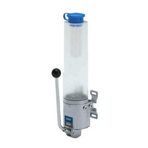
Explanation of signal
words for safety
NOTE
Emphasizes useful hints and
recommendations as well as
information to prevent property damage
and ensure efficient trouble-free
operation.
CAUTION
Indicates a dangerous situation that can
lead to light personal injury if
precautionary measures are ignored.
WARNING
Indicates a dangerous situation that
could lead to death or serious injury if
precautionary measures are ignored.
DANGER
Indicates a dangerous situation that will
lead to death or serious injury if
precautionary measures are ignored.
Safety
Read and carefully observe these installation
instructions before installing/operating/
troubleshooting assembly. Assembly must
be installed, maintained and repaired exclu-
sively by persons familiar with instructions.
Install assembly only after safety instruc-
tions and this guide have been read and are
completely understood.
Adequate personal protection must be
used to prevent splashing of material on skin
or in eyes.
Always disconnect power source (electri-
city, air or hydraulic) from pump when it is
not being used.
Equipment generates very high grease
pressure. Extreme caution should be used
when operating this equipment as material
leaks from loose or ruptured components
can inject fluid through skin and into body. If
any fluid appears to penetrate skin, seek
attention from a doctor immediately.
Do not treat injury as a simple cut. Tell
attending doctor exactly what type of fluid
was injected.
Any other use not in accordance with
instructions will result in loss of claim for
warranty or liability.
• Do not misuse, over-pressurize, modify
parts, use incompatible chemicals, fluids,
or use worn and/or damaged parts.
• Incorrect use may result in damage
to equipment caused by over or
under lurication.
• Do not exceed stated maximum
working pressure of pump or of lowest
rated component in your system.
• Always read and follow fluid manufactur-
er’s recommendations regarding fluid
compatibility, and use of protective
clothing and equipment.
• Pump should be mounted vertically
upright only.
• Install components of PS pump so
operator can always see low–level position
of pump reservoir.
• Each time reservoir has been refilled,
make sure pump is pumping lubricant.
• Failure to comply may result in personal
injury and/or damage to equipment.
Exclusion of liability
Manufacturer of PS pump will not accept
any liability for damages caused by:
• Lack of lubricant due to irregular refilling
of pump.
• Use of contaminated lubricants.
• Use of greases that are not or only
conditionally pumpable by PS pump.
• Inadequate disposal of used or contami-
nated lubricants and components that
have been in touch with lubricant.
• Unauthorized modification of system
components.
• Use of unapproved parts.
• Operation without adhering to minimum
pause time and respectively maximum
lubrication time († Table , page ).
Regulations for
prevention of
accidents
To prevent accidents, observe all city, state
and federal safety regulations of country
where product will be used.
